Download as PPS, PPTX


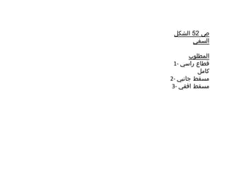


تناقش الوثيقة متطلبات رسم وتصميم مساقط قطاعات الجسام، بما في ذلك القطاعات الرأسية والجانبية والأفقية. تحتوي الوثيقة على تعليمات مفصلة حول كيفية تقديم هذه الرسوم في الصفحات 52 و53. يتم التركيز على أهمية كتابة الأبعاد على المساقط المختلفة.


