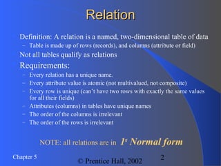
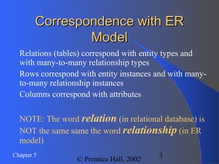
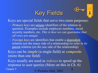
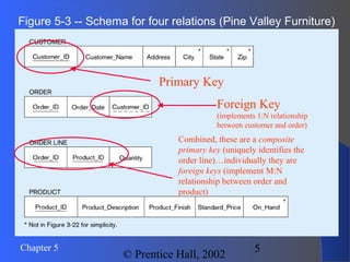
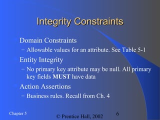
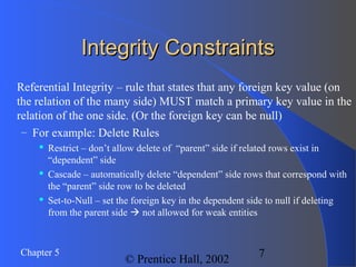
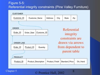
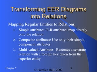
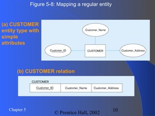
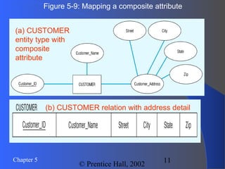
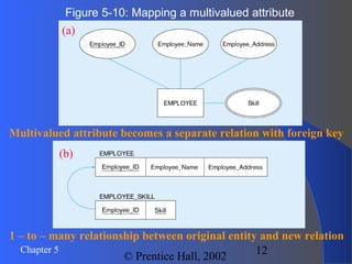
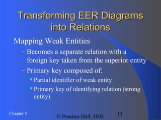
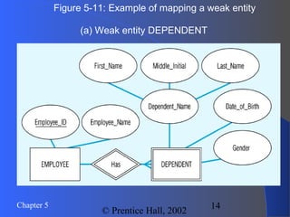
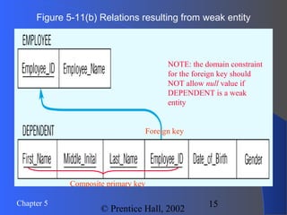
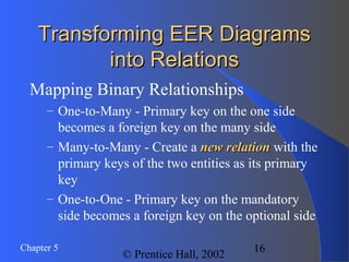
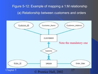
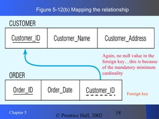
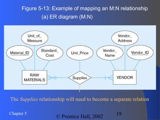
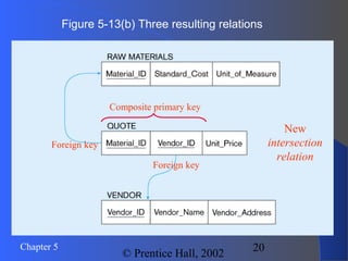
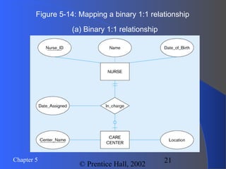
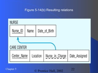
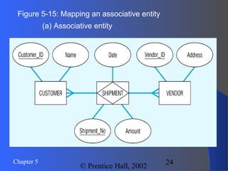
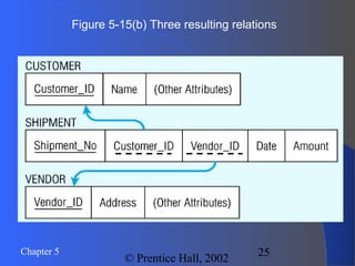
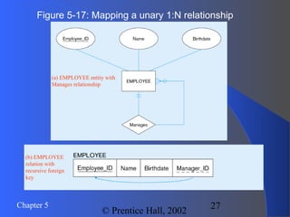
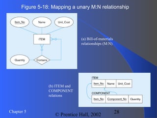
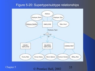
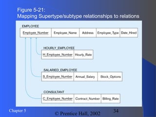
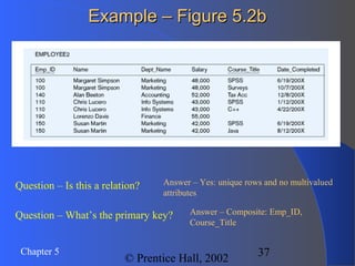
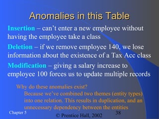
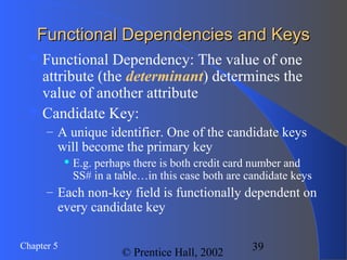
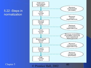
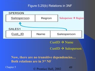
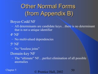
1
© Prentice Hall, 2002
Chapter 5:Chapter 5:
Logical Database DesignLogical Database Design
and the Relational Modeland the Relational Model
Modern Database Management
6th
Edition
Jeffrey A. Hoffer, Mary B. Prescott, Fred R.
McFadden
2Chapter 5
© Prentice Hall, 2002
RelationRelation
 Definition: A relation is a named, two-dimensional table of data
– Table is made up of rows (records), and columns (attribute or field)
 Not all tables qualify as relations
 Requirements:
– Every relation has a unique name.
– Every attribute value is atomic (not multivalued, not composite)
– Every row is unique (can’t have two rows with exactly the same values
for all their fields)
– Attributes (columns) in tables have unique names
– The order of the columns is irrelevant
– The order of the rows is irrelevant
NOTE: all relations are in 1st
Normal form
3Chapter 5
© Prentice Hall, 2002
Correspondence with ERCorrespondence with ER
ModelModel
 Relations (tables) correspond with entity types and
with many-to-many relationship types
 Rows correspond with entity instances and with many-
to-many relationship instances
 Columns correspond with attributes
 NOTE: The word relation (in relational database) is
NOT the same same the word relationship (in ER
model)
4Chapter 5
© Prentice Hall, 2002
Key FieldsKey Fields
 Keys are special fields that serve two main purposes:
– Primary keys are unique identifiers of the relation in
question. Examples include employee numbers, social
security numbers, etc. This is how we can guarantee that
all rows are unique
– Foreign keys are identifiers that enable a dependent
relation (on the many side of a relationship) to refer to its
parent relation (on the one side of the relationship)
 Keys can be simple (a single field) or composite
(more than one field)
 Keys usually are used as indexes to speed up the
response to user queries (More on this in Ch. 6)
5Chapter 5
© Prentice Hall, 2002
Figure 5-3 -- Schema for four relations (Pine Valley Furniture)
Primary Key
Foreign Key
(implements 1:N relationship
between customer and order)
Combined, these are a composite
primary key (uniquely identifies the
order line)…individually they are
foreign keys (implement M:N
relationship between order and
product)
6Chapter 5
© Prentice Hall, 2002
Integrity ConstraintsIntegrity Constraints
Domain Constraints
– Allowable values for an attribute. See Table 5-1
Entity Integrity
– No primary key attribute may be null. All primary
key fields MUST have data
Action Assertions
– Business rules. Recall from Ch. 4
7Chapter 5
© Prentice Hall, 2002
Integrity ConstraintsIntegrity Constraints
 Referential Integrity – rule that states that any foreign key value (on
the relation of the many side) MUST match a primary key value in the
relation of the one side. (Or the foreign key can be null)
– For example: Delete Rules
 Restrict – don’t allow delete of “parent” side if related rows exist in
“dependent” side
 Cascade – automatically delete “dependent” side rows that correspond with
the “parent” side row to be deleted
 Set-to-Null – set the foreign key in the dependent side to null if deleting
from the parent side  not allowed for weak entities
8Chapter 5
© Prentice Hall, 2002
Figure 5-5:
Referential integrity constraints (Pine Valley Furniture)
Referential
integrity
constraints are
drawn via arrows
from dependent to
parent table
9Chapter 5
© Prentice Hall, 2002
Transforming EER DiagramsTransforming EER Diagrams
into Relationsinto Relations
Mapping Regular Entities to Relations
1. Simple attributes: E-R attributes map directly
onto the relation
2. Composite attributes: Use only their simple,
component attributes
3. Multi-valued Attribute - Becomes a separate
relation with a foreign key taken from the
superior entity
10Chapter 5
© Prentice Hall, 2002
(a) CUSTOMER
entity type with
simple
attributes
Figure 5-8: Mapping a regular entity
(b) CUSTOMER relation
11Chapter 5
© Prentice Hall, 2002
(a) CUSTOMER
entity type with
composite
attribute
Figure 5-9: Mapping a composite attribute
(b) CUSTOMER relation with address detail
12Chapter 5
© Prentice Hall, 2002
Figure 5-10: Mapping a multivalued attribute
1 – to – many relationship between original entity and new relation
(a)
Multivalued attribute becomes a separate relation with foreign key
(b)
13Chapter 5
© Prentice Hall, 2002
Transforming EER DiagramsTransforming EER Diagrams
into Relationsinto Relations
Mapping Weak Entities
– Becomes a separate relation with a
foreign key taken from the superior entity
– Primary key composed of:
Partial identifier of weak entity
Primary key of identifying relation (strong
entity)
14Chapter 5
© Prentice Hall, 2002
Figure 5-11: Example of mapping a weak entity
(a) Weak entity DEPENDENT
15Chapter 5
© Prentice Hall, 2002
Figure 5-11(b) Relations resulting from weak entity
NOTE: the domain constraint
for the foreign key should
NOT allow null value if
DEPENDENT is a weak
entity
Foreign key
Composite primary key
16Chapter 5
© Prentice Hall, 2002
Transforming EER DiagramsTransforming EER Diagrams
into Relationsinto Relations
Mapping Binary Relationships
– One-to-Many - Primary key on the one side
becomes a foreign key on the many side
– Many-to-Many - Create a new relationnew relation with the
primary keys of the two entities as its primary
key
– One-to-One - Primary key on the mandatory
side becomes a foreign key on the optional side
17Chapter 5
© Prentice Hall, 2002
Figure 5-12: Example of mapping a 1:M relationship
(a) Relationship between customers and orders
Note the mandatory one
18Chapter 5
© Prentice Hall, 2002
Figure 5-12(b) Mapping the relationship
Again, no null value in the
foreign key…this is because
of the mandatory minimum
cardinality
Foreign key
19Chapter 5
© Prentice Hall, 2002
Figure 5-13: Example of mapping an M:N relationship
(a) ER diagram (M:N)
The Supplies relationship will need to become a separate relation
20Chapter 5
© Prentice Hall, 2002
Figure 5-13(b) Three resulting relations
New
intersection
relation
Foreign key
Foreign key
Composite primary key
21Chapter 5
© Prentice Hall, 2002
Figure 5-14: Mapping a binary 1:1 relationship
(a) Binary 1:1 relationship
22Chapter 5
© Prentice Hall, 2002
Figure 5-14(b) Resulting relations
23Chapter 5
© Prentice Hall, 2002
Transforming EER DiagramsTransforming EER Diagrams
into Relationsinto Relations
Mapping Associative Entities
– Identifier Not Assigned
Default primary key for the association
relation is composed of the primary keys of
the two entities (as in M:N relationship)
– Identifier Assigned
It is natural and familiar to end-users
Default identifier may not be unique
24Chapter 5
© Prentice Hall, 2002
Figure 5-15: Mapping an associative entity
(a) Associative entity
25Chapter 5
© Prentice Hall, 2002
Figure 5-15(b) Three resulting relations
26Chapter 5
© Prentice Hall, 2002
Transforming EER DiagramsTransforming EER Diagrams
into Relationsinto Relations
Mapping Unary Relationships
– One-to-Many - Recursive foreign key in the
same relation
– Many-to-Many - Two relations:
One for the entity type
One for an associative relation in which the
primary key has two attributes, both taken
from the primary key of the entity
27Chapter 5
© Prentice Hall, 2002
Figure 5-17: Mapping a unary 1:N relationship
(a) EMPLOYEE entity with
Manages relationship
(b) EMPLOYEE
relation with
recursive foreign
key
28Chapter 5
© Prentice Hall, 2002
Figure 5-18: Mapping a unary M:N relationship
(a) Bill-of-materials
relationships (M:N)
(b) ITEM and
COMPONENT
relations
29Chapter 5
© Prentice Hall, 2002
Transforming EER DiagramsTransforming EER Diagrams
into Relationsinto Relations
Mapping Ternary (and n-ary)
Relationships
– One relation for each entity and one
for the associative entity
– Associative entity has foreign keys
to each entity in the relationship
30Chapter 5
© Prentice Hall, 2002
Figure 5-19: Mapping a ternary relationship
(a) Ternary relationship with associative entity
31Chapter 5
© Prentice Hall, 2002
Figure 5-19(b) Mapping the ternary relationship
Remember that the
primary key MUST be
unique
32Chapter 5
© Prentice Hall, 2002
Transforming EER DiagramsTransforming EER Diagrams
into Relationsinto Relations
Mapping Supertype/Subtype Relationships
– One relation for supertype and for each subtype
– Supertype attributes (including identifier and
subtype discriminator) go into supertype relation
– Subtype attributes go into each subtype; primary
key of supertype relation also becomes primary
key of subtype relation
– 1:1 relationship established between supertype
and each subtype, with supertype as primary
table
33Chapter 5
© Prentice Hall, 2002
Figure 5-20: Supertype/subtype relationships
34Chapter 5
© Prentice Hall, 2002
Figure 5-21:
Mapping Supertype/subtype relationships to relations
35Chapter 5
© Prentice Hall, 2002
Data NormalizationData Normalization
Primarily a tool to validate and improve a
logical design so that it satisfies certain
constraints that avoid unnecessary
duplication of data
The process of decomposing relations with
anomalies to produce smaller, well-
structured relations
36Chapter 5
© Prentice Hall, 2002
Well-Structured RelationsWell-Structured Relations
 A relation that contains minimal data redundancy
and allows users to insert, delete, and update rows
without causing data inconsistencies
 Goal is to avoid anomalies
– Insertion Anomaly – adding new rows forces user to
create duplicate data
– Deletion Anomaly – deleting rows may cause a loss of
data that would be needed for other future rows
– Modification Anomaly – changing data in a row forces
changes to other rows because of duplication
General rule of thumb: a table should not pertain to
more than one entity type
37Chapter 5
© Prentice Hall, 2002
Example – Figure 5.2bExample – Figure 5.2b
Question – Is this a relation? Answer – Yes: unique rows and no multivalued
attributes
Question – What’s the primary key? Answer – Composite: Emp_ID,
Course_Title
38Chapter 5
© Prentice Hall, 2002
Anomalies in this TableAnomalies in this Table
Insertion – can’t enter a new employee without
having the employee take a class
Deletion – if we remove employee 140, we lose
information about the existence of a Tax Acc class
Modification – giving a salary increase to
employee 100 forces us to update multiple records
Why do these anomalies exist?
Because we’ve combined two themes (entity types)
into one relation. This results in duplication, and an
unnecessary dependency between the entities
39Chapter 5
© Prentice Hall, 2002
Functional Dependencies and KeysFunctional Dependencies and Keys
Functional Dependency: The value of one
attribute (the determinant) determines the
value of another attribute
Candidate Key:
– A unique identifier. One of the candidate keys
will become the primary key
 E.g. perhaps there is both credit card number and
SS# in a table…in this case both are candidate keys
– Each non-key field is functionally dependent on
every candidate key
40Chapter 5
© Prentice Hall, 2002
5.22 -Steps in
normalization
41Chapter 5
© Prentice Hall, 2002
First Normal FormFirst Normal Form
No multivalued attributes
Every attribute value is atomic
Fig. 5-2a is not in 1st
Normal Form
(multivalued attributes)  it is not a
relation
Fig. 5-2b is in 1st
Normal form
All relations are in 1st
Normal Form
42Chapter 5
© Prentice Hall, 2002
Second Normal FormSecond Normal Form
1NF plus every non-key attribute is fully
functionally dependent on the ENTIRE
primary key
– Every non-key attribute must be defined by the
entire key, not by only part of the key
– No partial functional dependencies
Fig. 5-2b is NOT in 2nd
Normal Form (see fig
5-23b)
43Chapter 5
© Prentice Hall, 2002
Fig 5.23(b) – FunctionalFig 5.23(b) – Functional
Dependencies in EMPLOYEE2Dependencies in EMPLOYEE2
EmpID CourseTitle DateCompletedSalaryDeptNameName
Dependency on entire primary key
Dependency on only part of the key
EmpID, CourseTitle  DateCompleted
EmpID  Name, DeptName, Salary
Therefore, NOT in 2nd
Normal Form!!
44Chapter 5
© Prentice Hall, 2002
Getting it into 2Getting it into 2ndnd
Normal FormNormal Form
 See p193 – decomposed into two separate
relations
EmpID SalaryDeptNameName
CourseTitle DateCompletedEmpID
Both are full
functional
dependencies
45Chapter 5
© Prentice Hall, 2002
Third Normal FormThird Normal Form
2NF PLUS no transitive dependencies
(one attribute functionally determines a
second, which functionally determines a
third)
Fig. 5-24, 5-25
46Chapter 5
© Prentice Hall, 2002
Figure 5-24 -- Relation with transitive dependency
(a) SALES relation with simple data
47Chapter 5
© Prentice Hall, 2002
Figure 5-24(b) Relation with transitive dependency
CustID  Name
CustID  Salesperson
CustID  Region
All this is OK
(2nd
NF)
BUT
CustID  Salesperson  Region
Transitive dependency
(not 3rd
NF)
48Chapter 5
© Prentice Hall, 2002
Figure 5.25 -- Removing a transitive dependency
(a) Decomposing the SALES relation
49Chapter 5
© Prentice Hall, 2002
Figure 5.25(b) Relations in 3NF
Now, there are no transitive dependencies…
Both relations are in 3rd
NF
CustID  Name
CustID  Salesperson
Salesperson  Region
50Chapter 5
© Prentice Hall, 2002
Other Normal FormsOther Normal Forms
(from Appendix B)(from Appendix B)
 Boyce-Codd NF
– All determinants are candidate keys…there is no determinant
that is not a unique identifier
 4th
NF
– No multivalued dependencies
 5th
NF
– No “lossless joins”
 Domain-key NF
– The “ultimate” NF…perfect elimination of all possible
anomalies

The Database Environment Chapter 5

  • 1.
    1 © Prentice Hall,2002 Chapter 5:Chapter 5: Logical Database DesignLogical Database Design and the Relational Modeland the Relational Model Modern Database Management 6th Edition Jeffrey A. Hoffer, Mary B. Prescott, Fred R. McFadden
  • 2.
    2Chapter 5 © PrenticeHall, 2002 RelationRelation  Definition: A relation is a named, two-dimensional table of data – Table is made up of rows (records), and columns (attribute or field)  Not all tables qualify as relations  Requirements: – Every relation has a unique name. – Every attribute value is atomic (not multivalued, not composite) – Every row is unique (can’t have two rows with exactly the same values for all their fields) – Attributes (columns) in tables have unique names – The order of the columns is irrelevant – The order of the rows is irrelevant NOTE: all relations are in 1st Normal form
  • 3.
    3Chapter 5 © PrenticeHall, 2002 Correspondence with ERCorrespondence with ER ModelModel  Relations (tables) correspond with entity types and with many-to-many relationship types  Rows correspond with entity instances and with many- to-many relationship instances  Columns correspond with attributes  NOTE: The word relation (in relational database) is NOT the same same the word relationship (in ER model)
  • 4.
    4Chapter 5 © PrenticeHall, 2002 Key FieldsKey Fields  Keys are special fields that serve two main purposes: – Primary keys are unique identifiers of the relation in question. Examples include employee numbers, social security numbers, etc. This is how we can guarantee that all rows are unique – Foreign keys are identifiers that enable a dependent relation (on the many side of a relationship) to refer to its parent relation (on the one side of the relationship)  Keys can be simple (a single field) or composite (more than one field)  Keys usually are used as indexes to speed up the response to user queries (More on this in Ch. 6)
  • 5.
    5Chapter 5 © PrenticeHall, 2002 Figure 5-3 -- Schema for four relations (Pine Valley Furniture) Primary Key Foreign Key (implements 1:N relationship between customer and order) Combined, these are a composite primary key (uniquely identifies the order line)…individually they are foreign keys (implement M:N relationship between order and product)
  • 6.
    6Chapter 5 © PrenticeHall, 2002 Integrity ConstraintsIntegrity Constraints Domain Constraints – Allowable values for an attribute. See Table 5-1 Entity Integrity – No primary key attribute may be null. All primary key fields MUST have data Action Assertions – Business rules. Recall from Ch. 4
  • 7.
    7Chapter 5 © PrenticeHall, 2002 Integrity ConstraintsIntegrity Constraints  Referential Integrity – rule that states that any foreign key value (on the relation of the many side) MUST match a primary key value in the relation of the one side. (Or the foreign key can be null) – For example: Delete Rules  Restrict – don’t allow delete of “parent” side if related rows exist in “dependent” side  Cascade – automatically delete “dependent” side rows that correspond with the “parent” side row to be deleted  Set-to-Null – set the foreign key in the dependent side to null if deleting from the parent side  not allowed for weak entities
  • 8.
    8Chapter 5 © PrenticeHall, 2002 Figure 5-5: Referential integrity constraints (Pine Valley Furniture) Referential integrity constraints are drawn via arrows from dependent to parent table
  • 9.
    9Chapter 5 © PrenticeHall, 2002 Transforming EER DiagramsTransforming EER Diagrams into Relationsinto Relations Mapping Regular Entities to Relations 1. Simple attributes: E-R attributes map directly onto the relation 2. Composite attributes: Use only their simple, component attributes 3. Multi-valued Attribute - Becomes a separate relation with a foreign key taken from the superior entity
  • 10.
    10Chapter 5 © PrenticeHall, 2002 (a) CUSTOMER entity type with simple attributes Figure 5-8: Mapping a regular entity (b) CUSTOMER relation
  • 11.
    11Chapter 5 © PrenticeHall, 2002 (a) CUSTOMER entity type with composite attribute Figure 5-9: Mapping a composite attribute (b) CUSTOMER relation with address detail
  • 12.
    12Chapter 5 © PrenticeHall, 2002 Figure 5-10: Mapping a multivalued attribute 1 – to – many relationship between original entity and new relation (a) Multivalued attribute becomes a separate relation with foreign key (b)
  • 13.
    13Chapter 5 © PrenticeHall, 2002 Transforming EER DiagramsTransforming EER Diagrams into Relationsinto Relations Mapping Weak Entities – Becomes a separate relation with a foreign key taken from the superior entity – Primary key composed of: Partial identifier of weak entity Primary key of identifying relation (strong entity)
  • 14.
    14Chapter 5 © PrenticeHall, 2002 Figure 5-11: Example of mapping a weak entity (a) Weak entity DEPENDENT
  • 15.
    15Chapter 5 © PrenticeHall, 2002 Figure 5-11(b) Relations resulting from weak entity NOTE: the domain constraint for the foreign key should NOT allow null value if DEPENDENT is a weak entity Foreign key Composite primary key
  • 16.
    16Chapter 5 © PrenticeHall, 2002 Transforming EER DiagramsTransforming EER Diagrams into Relationsinto Relations Mapping Binary Relationships – One-to-Many - Primary key on the one side becomes a foreign key on the many side – Many-to-Many - Create a new relationnew relation with the primary keys of the two entities as its primary key – One-to-One - Primary key on the mandatory side becomes a foreign key on the optional side
  • 17.
    17Chapter 5 © PrenticeHall, 2002 Figure 5-12: Example of mapping a 1:M relationship (a) Relationship between customers and orders Note the mandatory one
  • 18.
    18Chapter 5 © PrenticeHall, 2002 Figure 5-12(b) Mapping the relationship Again, no null value in the foreign key…this is because of the mandatory minimum cardinality Foreign key
  • 19.
    19Chapter 5 © PrenticeHall, 2002 Figure 5-13: Example of mapping an M:N relationship (a) ER diagram (M:N) The Supplies relationship will need to become a separate relation
  • 20.
    20Chapter 5 © PrenticeHall, 2002 Figure 5-13(b) Three resulting relations New intersection relation Foreign key Foreign key Composite primary key
  • 21.
    21Chapter 5 © PrenticeHall, 2002 Figure 5-14: Mapping a binary 1:1 relationship (a) Binary 1:1 relationship
  • 22.
    22Chapter 5 © PrenticeHall, 2002 Figure 5-14(b) Resulting relations
  • 23.
    23Chapter 5 © PrenticeHall, 2002 Transforming EER DiagramsTransforming EER Diagrams into Relationsinto Relations Mapping Associative Entities – Identifier Not Assigned Default primary key for the association relation is composed of the primary keys of the two entities (as in M:N relationship) – Identifier Assigned It is natural and familiar to end-users Default identifier may not be unique
  • 24.
    24Chapter 5 © PrenticeHall, 2002 Figure 5-15: Mapping an associative entity (a) Associative entity
  • 25.
    25Chapter 5 © PrenticeHall, 2002 Figure 5-15(b) Three resulting relations
  • 26.
    26Chapter 5 © PrenticeHall, 2002 Transforming EER DiagramsTransforming EER Diagrams into Relationsinto Relations Mapping Unary Relationships – One-to-Many - Recursive foreign key in the same relation – Many-to-Many - Two relations: One for the entity type One for an associative relation in which the primary key has two attributes, both taken from the primary key of the entity
  • 27.
    27Chapter 5 © PrenticeHall, 2002 Figure 5-17: Mapping a unary 1:N relationship (a) EMPLOYEE entity with Manages relationship (b) EMPLOYEE relation with recursive foreign key
  • 28.
    28Chapter 5 © PrenticeHall, 2002 Figure 5-18: Mapping a unary M:N relationship (a) Bill-of-materials relationships (M:N) (b) ITEM and COMPONENT relations
  • 29.
    29Chapter 5 © PrenticeHall, 2002 Transforming EER DiagramsTransforming EER Diagrams into Relationsinto Relations Mapping Ternary (and n-ary) Relationships – One relation for each entity and one for the associative entity – Associative entity has foreign keys to each entity in the relationship
  • 30.
    30Chapter 5 © PrenticeHall, 2002 Figure 5-19: Mapping a ternary relationship (a) Ternary relationship with associative entity
  • 31.
    31Chapter 5 © PrenticeHall, 2002 Figure 5-19(b) Mapping the ternary relationship Remember that the primary key MUST be unique
  • 32.
    32Chapter 5 © PrenticeHall, 2002 Transforming EER DiagramsTransforming EER Diagrams into Relationsinto Relations Mapping Supertype/Subtype Relationships – One relation for supertype and for each subtype – Supertype attributes (including identifier and subtype discriminator) go into supertype relation – Subtype attributes go into each subtype; primary key of supertype relation also becomes primary key of subtype relation – 1:1 relationship established between supertype and each subtype, with supertype as primary table
  • 33.
    33Chapter 5 © PrenticeHall, 2002 Figure 5-20: Supertype/subtype relationships
  • 34.
    34Chapter 5 © PrenticeHall, 2002 Figure 5-21: Mapping Supertype/subtype relationships to relations
  • 35.
    35Chapter 5 © PrenticeHall, 2002 Data NormalizationData Normalization Primarily a tool to validate and improve a logical design so that it satisfies certain constraints that avoid unnecessary duplication of data The process of decomposing relations with anomalies to produce smaller, well- structured relations
  • 36.
    36Chapter 5 © PrenticeHall, 2002 Well-Structured RelationsWell-Structured Relations  A relation that contains minimal data redundancy and allows users to insert, delete, and update rows without causing data inconsistencies  Goal is to avoid anomalies – Insertion Anomaly – adding new rows forces user to create duplicate data – Deletion Anomaly – deleting rows may cause a loss of data that would be needed for other future rows – Modification Anomaly – changing data in a row forces changes to other rows because of duplication General rule of thumb: a table should not pertain to more than one entity type
  • 37.
    37Chapter 5 © PrenticeHall, 2002 Example – Figure 5.2bExample – Figure 5.2b Question – Is this a relation? Answer – Yes: unique rows and no multivalued attributes Question – What’s the primary key? Answer – Composite: Emp_ID, Course_Title
  • 38.
    38Chapter 5 © PrenticeHall, 2002 Anomalies in this TableAnomalies in this Table Insertion – can’t enter a new employee without having the employee take a class Deletion – if we remove employee 140, we lose information about the existence of a Tax Acc class Modification – giving a salary increase to employee 100 forces us to update multiple records Why do these anomalies exist? Because we’ve combined two themes (entity types) into one relation. This results in duplication, and an unnecessary dependency between the entities
  • 39.
    39Chapter 5 © PrenticeHall, 2002 Functional Dependencies and KeysFunctional Dependencies and Keys Functional Dependency: The value of one attribute (the determinant) determines the value of another attribute Candidate Key: – A unique identifier. One of the candidate keys will become the primary key  E.g. perhaps there is both credit card number and SS# in a table…in this case both are candidate keys – Each non-key field is functionally dependent on every candidate key
  • 40.
    40Chapter 5 © PrenticeHall, 2002 5.22 -Steps in normalization
  • 41.
    41Chapter 5 © PrenticeHall, 2002 First Normal FormFirst Normal Form No multivalued attributes Every attribute value is atomic Fig. 5-2a is not in 1st Normal Form (multivalued attributes)  it is not a relation Fig. 5-2b is in 1st Normal form All relations are in 1st Normal Form
  • 42.
    42Chapter 5 © PrenticeHall, 2002 Second Normal FormSecond Normal Form 1NF plus every non-key attribute is fully functionally dependent on the ENTIRE primary key – Every non-key attribute must be defined by the entire key, not by only part of the key – No partial functional dependencies Fig. 5-2b is NOT in 2nd Normal Form (see fig 5-23b)
  • 43.
    43Chapter 5 © PrenticeHall, 2002 Fig 5.23(b) – FunctionalFig 5.23(b) – Functional Dependencies in EMPLOYEE2Dependencies in EMPLOYEE2 EmpID CourseTitle DateCompletedSalaryDeptNameName Dependency on entire primary key Dependency on only part of the key EmpID, CourseTitle  DateCompleted EmpID  Name, DeptName, Salary Therefore, NOT in 2nd Normal Form!!
  • 44.
    44Chapter 5 © PrenticeHall, 2002 Getting it into 2Getting it into 2ndnd Normal FormNormal Form  See p193 – decomposed into two separate relations EmpID SalaryDeptNameName CourseTitle DateCompletedEmpID Both are full functional dependencies
  • 45.
    45Chapter 5 © PrenticeHall, 2002 Third Normal FormThird Normal Form 2NF PLUS no transitive dependencies (one attribute functionally determines a second, which functionally determines a third) Fig. 5-24, 5-25
  • 46.
    46Chapter 5 © PrenticeHall, 2002 Figure 5-24 -- Relation with transitive dependency (a) SALES relation with simple data
  • 47.
    47Chapter 5 © PrenticeHall, 2002 Figure 5-24(b) Relation with transitive dependency CustID  Name CustID  Salesperson CustID  Region All this is OK (2nd NF) BUT CustID  Salesperson  Region Transitive dependency (not 3rd NF)
  • 48.
    48Chapter 5 © PrenticeHall, 2002 Figure 5.25 -- Removing a transitive dependency (a) Decomposing the SALES relation
  • 49.
    49Chapter 5 © PrenticeHall, 2002 Figure 5.25(b) Relations in 3NF Now, there are no transitive dependencies… Both relations are in 3rd NF CustID  Name CustID  Salesperson Salesperson  Region
  • 50.
    50Chapter 5 © PrenticeHall, 2002 Other Normal FormsOther Normal Forms (from Appendix B)(from Appendix B)  Boyce-Codd NF – All determinants are candidate keys…there is no determinant that is not a unique identifier  4th NF – No multivalued dependencies  5th NF – No “lossless joins”  Domain-key NF – The “ultimate” NF…perfect elimination of all possible anomalies