Download to read offline
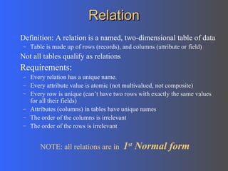
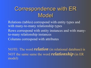
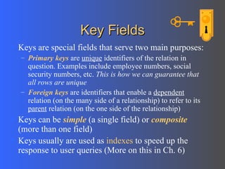
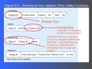
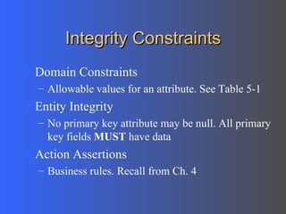
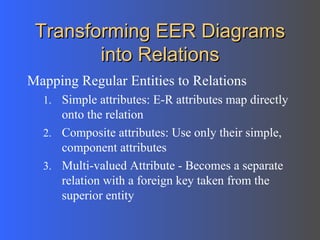
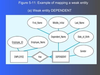
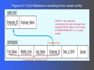
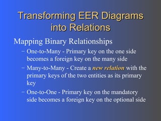
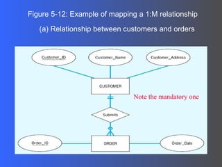
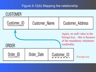
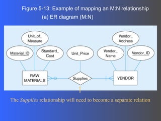
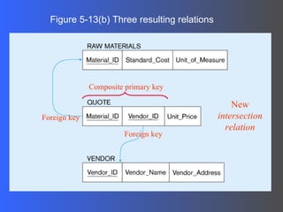
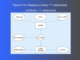
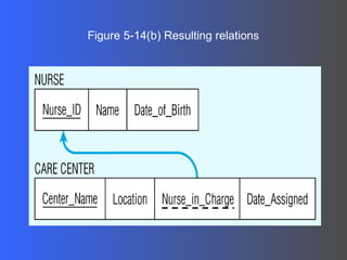
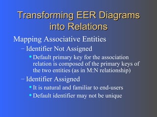
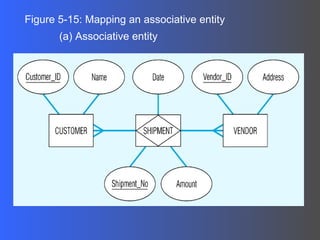
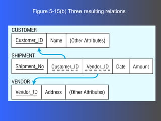

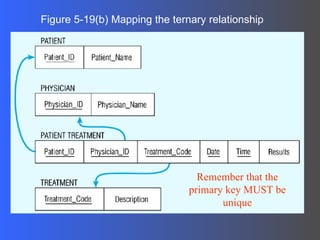
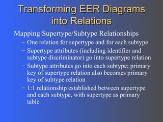
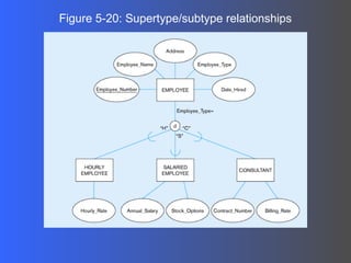
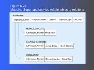

- The document discusses logical database design and the relational model. It defines key concepts like relations, attributes, keys, and normal forms. - Relations are two-dimensional tables made up of rows and columns. Each relation must have a unique name and atomic attribute values. - Primary keys uniquely identify rows and foreign keys link relations based on common attributes representing relationships. - The document covers transforming entity-relationship diagrams into relational schemas through mapping of entities, attributes, relationships and ensuring normalization.