Download to read offline

![VI Semester Civil CE6602 Structural Analysis-II by K.Kalaipandian AP / Civil Page 15
, MA
WR
W (CB
W. R sin
0, MB
0
1 cos WR
, TA
WR
2
W (CX
WR (1 cos )
0, TB
WR (1 cos ) 0
ds T ds
M
2 EI 2 GJ
2 2
1
( WR sin )2
R d
1
[ WR (1 cos )]2
R d
2GJ
2
1
(W2
R2
sin2
)R d
1
[W
2
cos 2
2cos )R d
2
R2
(1
2 2
cos2 1 2 3 1 cos2
1
1
W2
R3
d x W R 1 2cos d
2 2GJ 2
0
W
and unif
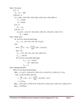
Step1: Shear force:
SF at the section X, Fo
Fo is independent of orm throughout.
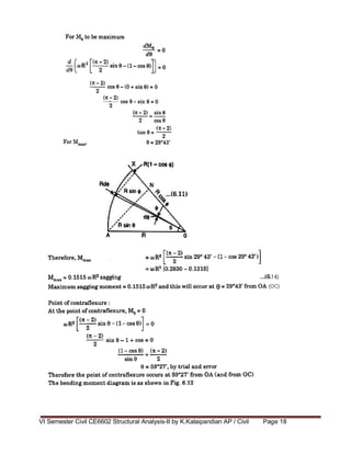
Step2: Bending Moment :
BM at the section X, M )
M
At
At
2
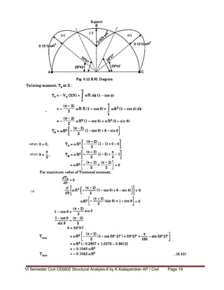
Step3: Twisting Moment :
Twisting moment at the section X, T )
T
At
At
2
Step4: Deflection at the free end B:
Method of strain energy is used to find the deflection at the free end B.
2 2
Strain energy, U
2EI 0 0
2EI 0
2GJ 0
2EI 0](https://image.slidesharecdn.com/sa-iinotes-220712170946-dfc1d4a5/85/SA-II-Notes-pdf-15-320.jpg)

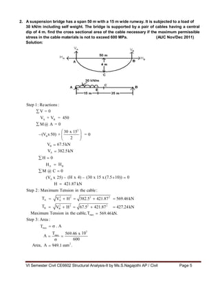
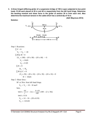
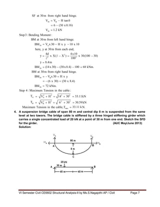
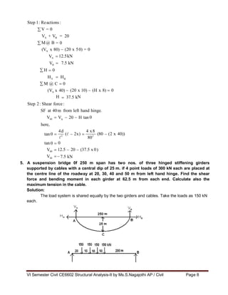
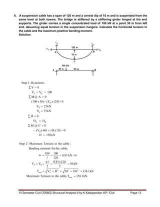
This document contains a question bank for the Structural Analysis-II subject. It includes 20 multiple choice questions related to space and cable structures. Some key questions ask about examples of curved beams, the nature of forces in cables, tension coefficients, space frames, types of cable structures, and methods of analyzing space trusses. It also provides the solutions to 3 numerical problems involving calculating reactions, shear forces, bending moments, and tensions in cables for suspension bridge structures.


