SlideShare a Scribd company logo
027 Electrical & Electronics Principles 
Pg 1 
8.0A ROTATING MACHINES 
8.A.0 Torque 
A torque is defined as the turning moment of a force and its SI Unit is Newton metre (Nm). 
The torque about a point is equal to the force times the distance measured perpendicular to the force. 
Examples 
Torque in a couple 
Ex 4: t = F x L sinθ 
© Seychelles Institutes of Technology Prepared by Mr. Dinesh
027 Electrical & Electronics Principles 
Pg 2 
8.0A ROTATING MACHINES 
8.A.1 Torque on a coil in a magnetic field 
Fig 1 
Fig 1 (a) is the field between two magnets, (b) the field due to a current in a straight wire and (c) the 
resulting field if they are put together. This last field is known as the "catapult" field because it tends to 
catapult the wire out of the field in the direction shown by the arrow. 
Fig 2 
Fig 2(a) show If a coil carrying a current is placed in a magnetic field it will experience a force on two 
of its sides in such a way as to make the coil rotate. 
Fig 2(b) shows coil will rotate from the 'double catapult' field diagram. Since the current moves along 
the two opposite sides of the coil in opposite directions the two sides receive a force in opposite 
directions also, thus turning the coil. 
© Seychelles Institutes of Technology Prepared by Mr. Dinesh
027 Electrical & Electronics Principles 
Pg 3 
8.0A ROTATING MACHINES 
8.A.2 Torque on a current carrying conductor 
Consider a rectangular coil in Fig 3 when the plane of the coil is lying along the field lines (θ = 90o) 
Where, τ = torque (Nm) 
L = length (m) 
W = width (m) 
B = magnetic field (Wb) 
I = current (A) 
Fig 3 
τ = F x perpendicular distance 
τ = F x W 
= BIL x W 
= BI(LW) 
τ = BIA 
© Seychelles Institutes of Technology Prepared by Mr. Dinesh
027 Electrical & Electronics Principles 
Pg 4 
8.0A ROTATING MACHINES 
Consider a number of rectangular coil in fig 4 when the plane of the coil is rotating along the field lines 
Where, τ = torque (Nm) 
L = length (m) 
W = width (m) 
d = perpendicular distance (m) 
θ = angle (°) 
B = magnetic field (Wb) 
I = current (A) 
N = number of turns 
Fig 4 
τ = F x perpendicular distance 
τ = F x d 
= BILN x Wsinθ 
= BI(LW)Nsinθ 
τ = BIANsinθ 
© Seychelles Institutes of Technology Prepared by Mr. Dinesh
027 Electrical & Electronics Principles 
Pg 5 
8.0A ROTATING MACHINES 
8.A.3 Solved work examples on “torque on a current carrying conductor” 
Work example 1 
Calculate the torque needed to hold a coil of 20 turns and area 8cm2 at an angle of 60o to a magnetic 
field of flux density 0.1T if the coil carries a current of 0.5 A. 
Solution 
Torque, τ = BANIsinθ 
= 0.1x20x8x10-4sin 60° 
τ = 8x10⁻⁴ Nm 
Work example 2 
a) What is the maximum torque on a 150-turn square loop of wire 18.0 cm on a side that carries a 50.0A 
current in a 1.60-T field? 
b) What is the torque when θ is 10.9°? 
Solution 
a) Maximum torque, τ = BANIsinθ 
= 1.60x150x0.0182 x50.0sin 90° 
τ = 
b) When θ is 10.9°, τ = BANIsinθ 
= 1.60x150x0.182 x50.0sin 10.9° 
τ = 
© Seychelles Institutes of Technology Prepared by Mr. Dinesh
027 Electrical & Electronics Principles 
Pg 6 
8.0A ROTATING MACHINES 
8.A.4 E.m.f. induced in a straight conductor in a uniform magnetic field 
When a straight conductor is moved through a magnetic field an e.m.f. is induced between its ends. This 
movement must be in such a direction that the conductor cuts through the lines of magnetic flux, and 
will be a maximum when it moves at right angles to the field (Fig 5). 
Where, E = e.m.f. induced (V) 
L = length (m) 
B = magnetic field (Wb) 
v = velocity (m/s) 
Fig 5 
If the conductor moves with velocity v at right angles to the field then the flux cut per second will be 
BvL (since the conductor will sweep out an area vL every second). 
But the rate of cutting flux is equal to the e.m.f. induced in the conductor. Therefore 
E = BLv 
© Seychelles Institutes of Technology Prepared by Mr. Dinesh
027 Electrical & Electronics Principles 
Pg 7 
8.0A ROTATING MACHINES 
If the conductor cuts through the flux at an angle θ ( in Fig 5), where θ is the angle between the magnetic 
field and the direction of motion, the equation becomes 
E = BLv sinθ 
8.A.5 Solved work examples on Emf induced on a straight conductor 
Work example 1 
Calculate 
a) The e.m.f. generated between the wing tips of an aircraft that is flying horizontally at 200 ms-1 in a region 
where the vertical component of the Earth's magnetic field is 4.0x10⁻⁵ T, if the aircraft has a wingspan of 25 m. 
b) What will be the e.m.f. if the θ = 30°. 
Solution 
a) Maximum e.m.f., E = BLvsinθ 
= 4.0x10-5x25x200 sin 90° 
E = 0.2V 
b) When θ is 30°, E = BANIsinθ 
= 4.0x10-5x150x200 sin 30° 
E = 0.1V 
© Seychelles Institutes of Technology Prepared by Mr. Dinesh
027 Electrical & Electronics Principles 
Pg 8 
8.0A ROTATING MACHINES 
8.A.4 Emf induced in a straight conductor rotating in a uniform magnetic field 
Consider the Fig 6, a diagram of an electrical generator. A generator with a single rectangular coil 
rotated at constant angular velocity in a uniform magnetic field produces an e.m.f. that varies 
sinusoidally in time. Note the generator is similar to a motor, except the shaft is rotated to produce a 
current rather than the other way around. 
Where, E = e.m.f. induced (V) 
L = length (m) 
B = magnetic field (Wb) 
v = velocity (m/s) 
θ = angle (°) 
ω = angular velocity (rad/s) 
Fig 6 
The induced e.m.f. by considering only the side wires. 
Motional e.m.f. is given to be E = BLv, where the velocity v is perpendicular to the magnetic field B 
Here, the velocity is at an angle θ with B, so that its component perpendicular to B is vsinθ. 
Thus in this case the e.m.f. induced on each side is E = BLvsinθ, and they are in the same direction. 
The total EMF ε around the loop is then: E = 2BLvsinθ 
This expression is valid, but it does not give EMF as a function of time. 
© Seychelles Institutes of Technology Prepared by Mr. Dinesh
027 Electrical & Electronics Principles 
Pg 9 
8.0A ROTATING MACHINES 
To find the time dependence of EMF, we assume the coil rotates at a constant angular velocity ω. 
The angle θ is related to angular velocity by θ = ωt, so that: E = 2Blvsinωt 
Now, linear velocity v is related to angular velocity by v = rω. 
Here r = w/2, so that v = (w/2)ω, and: 
E = 2BLw2ωsinωt 
E = (Lw)Bωsinωt 
Noting that the area of the loop is A = Lw, and allowing for N loops, we find that: 
E = NABω sinωt 
The maximum value of the e.m.f (Emax) is when θ (= ωt) = 90o, is given by 
E = NABω 
© Seychelles Institutes of Technology Prepared by Mr. Dinesh
027 Electrical & Electronics Principles 
Pg 10 
8.0A ROTATING MACHINES 
8.A.5 Solved work examples on Emf induced in a rotating in a uniform magnetic field 
Work example 1 
Calculate 
a) The maximum value of the e.m.f generated in a coil with 200 turns and of area 10 cm2 rotating at 60 
radians per second in a field of flux density 0.1 T. 
b) The e.m.f. when θ = 60o 
Solution 
a) Maximum e.m.f., E = BANωsinθ 
= 0.1x10-5x200x60 sin 90° 
E = 1.2V 
b) When θ is 30°, E = BANωsinθ 
= 0.1x10-5x200x60 sin 60° 
E = 1.04V 
Notice the use of radians per second. 
© Seychelles Institutes of Technology Prepared by Mr. Dinesh
027 Electrical & Electronics Principles 
Pg 11 
8.0A ROTATING MACHINES 
8.A.6 Power generated in rotating machines 
The linear motion of a conductor through a magnetic field, the mechanical power supplied is equal to 
the electrical power generated. 
8.1.7 Derivation of power in rotating machines 
For a rotating object, the linear distance covered at the circumference of rotation is the product of the 
radius with the angle covered. 
That is: 
Linear distance = radius × angular distance. 
By definition, 
Linear distance = linear speed × time = radius × angular speed × time. 
By the definition of torque: 
Torque = radius × force. 
These two values can be substituted into the definition of power: 
Power = Force × Linear distance 
Time 
= (Torque⁄Radius)× (Radius × Angular speed) 
Time 
= Torque × Angular speed 
or 
Power = Torque × 2π × Rotational speed 
Where, Torque, τ (N/m) 
Angular speed, ω (rad/s) 
Rotational speed, n (rev/s) 
Radius, r (m) 
© Seychelles Institutes of Technology Prepared by Mr. Dinesh
027 Electrical & Electronics Principles 
Pg 12 
8.0A ROTATING MACHINES 
Rotational power is given by, 
P = ω. τ 
Where, ω, angular velocity is defined as the rate of change of angular displacement which 
specifies the angular speed (rotational speed) of an object and the axis about which the 
object is rotating. Measured in radian per second (rad/s) 
τ, torque is defined as the moment of force is the tendency of a force to rotate an object 
about an axis. Measured in newton per metre (N/m) 
P, In rotational systems, power is defined as the product of the torque and angular 
velocity. Measured in watts (W) 
8.A.8 Power efficiency 
Power efficiency is defined as the ratio of output power divided by input power. 
Ƞ = 100% · 
Where, ƞ = efficiency (%) 
Pout = output power (W) 
Pin = input power (W) 
퐏퐨퐮퐭 
퐏퐢퐧 
© Seychelles Institutes of Technology Prepared by Mr. Dinesh
027 Electrical & Electronics Principles 
Pg 13 
8.0A ROTATING MACHINES 
8.A.9 Solved work examples on power in rotating machines 
Work example 1 
A machine is rotating with speed of 3000 rev/min (rpm) consumes 5kW. Calculate the torque of the 
shaft. 
Solution 
Given, ƞ = 3000 rpm 
P = 5kW 
τ = ? 
Using τ = 퐏/ퟐ훑ƞ 
= (5 × 1000) ÷ [(2π × 
3000 
60 
)] 
τ = 15.9 N/m 
Work example 2 
An electric motor has an input power consumption of 50 watts. The motor was activated for 60 seconds 
and produced work of 2970 joules. Find the efficiency of motor? 
Solution 
Given, Pin = 50W 
t = 60s 
E = 2970J 
ƞ = ? 
Pout = ? 
Using Pout = E / t 
= 2970/60 
Pout = 49.45W 
Now ƞ = ퟏퟎퟎ% × 퐏퐨퐮퐭 / 퐏퐢퐧 
= ퟏퟎퟎ × (ퟒퟗ. ퟗퟓ/ퟓퟎ) 
ƞ = ퟗퟗ% 
© Seychelles Institutes of Technology Prepared by Mr. Dinesh

More Related Content

What's hot

Dcmachine
DcmachineDcmachine
Dcmachine
am
 
Electrical machines lecture notes
Electrical machines lecture notesElectrical machines lecture notes
Electrical machines lecture notes
IYAKAREMYE Jean De Dieu
 
Performance of dc motors experiment 2
Performance of dc motors experiment 2Performance of dc motors experiment 2
Performance of dc motors experiment 2
Karimi LordRamza
 
Eg1108 d cmotors
Eg1108 d cmotorsEg1108 d cmotors
Eg1108 d cmotors
Memo Love
 
Elecromechnical conversion & Rotating machines
Elecromechnical conversion & Rotating machinesElecromechnical conversion & Rotating machines
Elecromechnical conversion & Rotating machines
KATHANSANJAYSHAH
 
Qbeecs2
Qbeecs2Qbeecs2
Qbeecs2
Ubaid Abid
 
Dc machiness
Dc machinessDc machiness
Dc machiness
Deepa Rani
 
53669836 brake-test-on-a-d
53669836 brake-test-on-a-d53669836 brake-test-on-a-d
53669836 brake-test-on-a-d
thicman
 
Dc motor
Dc motorDc motor
Dc motor
ashok singh
 
Alternator losses and efficiency
Alternator losses and efficiencyAlternator losses and efficiency
Alternator losses and efficiency
Jessica Laine Tumbaga
 
testing of dc machine
testing of dc machinetesting of dc machine
testing of dc machine
Mrityunjai Yadav
 
Dc generator
Dc generatorDc generator
Dc generator
Joseph Raj
 
Dc motor
Dc motorDc motor
Dc motor
Ashvani Shukla
 
DC MACHINES
DC MACHINESDC MACHINES
DC MACHINES
Vikas Kalwani
 
Lecture 5
Lecture 5Lecture 5
Lecture 5
Asif Memon
 
Emc510 s emec_lect_notes_sem-1_2016_lecture-2
Emc510 s emec_lect_notes_sem-1_2016_lecture-2Emc510 s emec_lect_notes_sem-1_2016_lecture-2
Emc510 s emec_lect_notes_sem-1_2016_lecture-2
Timoteus Ikaku
 
Electromechanical Energy Conversion ppt 2
Electromechanical Energy Conversion ppt 2Electromechanical Energy Conversion ppt 2
Electromechanical Energy Conversion ppt 2
Anirudhan Guru
 
Electromechanical energy conversion
Electromechanical energy conversionElectromechanical energy conversion
Electromechanical energy conversion
Mohammed Waris Senan
 

What's hot (18)

Dcmachine
DcmachineDcmachine
Dcmachine
 
Electrical machines lecture notes
Electrical machines lecture notesElectrical machines lecture notes
Electrical machines lecture notes
 
Performance of dc motors experiment 2
Performance of dc motors experiment 2Performance of dc motors experiment 2
Performance of dc motors experiment 2
 
Eg1108 d cmotors
Eg1108 d cmotorsEg1108 d cmotors
Eg1108 d cmotors
 
Elecromechnical conversion & Rotating machines
Elecromechnical conversion & Rotating machinesElecromechnical conversion & Rotating machines
Elecromechnical conversion & Rotating machines
 
Qbeecs2
Qbeecs2Qbeecs2
Qbeecs2
 
Dc machiness
Dc machinessDc machiness
Dc machiness
 
53669836 brake-test-on-a-d
53669836 brake-test-on-a-d53669836 brake-test-on-a-d
53669836 brake-test-on-a-d
 
Dc motor
Dc motorDc motor
Dc motor
 
Alternator losses and efficiency
Alternator losses and efficiencyAlternator losses and efficiency
Alternator losses and efficiency
 
testing of dc machine
testing of dc machinetesting of dc machine
testing of dc machine
 
Dc generator
Dc generatorDc generator
Dc generator
 
Dc motor
Dc motorDc motor
Dc motor
 
DC MACHINES
DC MACHINESDC MACHINES
DC MACHINES
 
Lecture 5
Lecture 5Lecture 5
Lecture 5
 
Emc510 s emec_lect_notes_sem-1_2016_lecture-2
Emc510 s emec_lect_notes_sem-1_2016_lecture-2Emc510 s emec_lect_notes_sem-1_2016_lecture-2
Emc510 s emec_lect_notes_sem-1_2016_lecture-2
 
Electromechanical Energy Conversion ppt 2
Electromechanical Energy Conversion ppt 2Electromechanical Energy Conversion ppt 2
Electromechanical Energy Conversion ppt 2
 
Electromechanical energy conversion
Electromechanical energy conversionElectromechanical energy conversion
Electromechanical energy conversion
 

Similar to Rotating machines part 1

Basic Electrical Engineering- AC Circuit
Basic Electrical Engineering- AC CircuitBasic Electrical Engineering- AC Circuit
Basic Electrical Engineering- AC Circuit
Bhavesh jesadia
 
Ac circuits
Ac circuitsAc circuits
Ac circuits
Ekeeda
 
3. a. c. circits
3. a. c. circits 3. a. c. circits
3. a. c. circits
Ekeeda
 
Ac circuits
Ac circuitsAc circuits
Ac circuits
Ekeeda
 
L16 1 ph-ac
L16 1 ph-acL16 1 ph-ac
L16 1 ph-ac
Satyakam
 
Elecmachine
ElecmachineElecmachine
Elecmachine
Hassan Tirmizi
 
BEEM UII.pptx
BEEM UII.pptxBEEM UII.pptx
BEEM UII.pptx
MalathyN5
 
12th physics-solution set 3
12th physics-solution set 312th physics-solution set 3
12th physics-solution set 3
vandna123
 
nothing
nothingnothing
nothing
Random guy
 
Maxwell Equations (2)
Maxwell Equations (2)Maxwell Equations (2)
Maxwell Equations (2)
Fredrick Kendrick
 
Research on Transformer Core Vibration under DC Bias Based on Multi-field Cou...
Research on Transformer Core Vibration under DC Bias Based on Multi-field Cou...Research on Transformer Core Vibration under DC Bias Based on Multi-field Cou...
Research on Transformer Core Vibration under DC Bias Based on Multi-field Cou...
inventionjournals
 
Design of transformer and chock coil
Design of transformer and chock coilDesign of transformer and chock coil
Design of transformer and chock coil
Shubham Champaneri
 
Incomplete PPT on first topic.pptx [Autosaved] [Autosaved].ppt
Incomplete PPT on first topic.pptx [Autosaved] [Autosaved].pptIncomplete PPT on first topic.pptx [Autosaved] [Autosaved].ppt
Incomplete PPT on first topic.pptx [Autosaved] [Autosaved].ppt
ShubhobrataRudr
 
Anschp31
Anschp31Anschp31
Anschp31
FnC Music
 
Generator ppt 1
Generator ppt 1Generator ppt 1
Generator ppt 1
BrijeshPrasad13
 
Concept of general terms pertaining to rotating machines
Concept of general terms pertaining to rotating machinesConcept of general terms pertaining to rotating machines
Concept of general terms pertaining to rotating machines
vishalgohel12195
 
Rotating magnetic field
Rotating magnetic fieldRotating magnetic field
Rotating magnetic field
ASHISH RAJ
 
Electrical System Design transformer 4.pptx
Electrical System Design transformer 4.pptxElectrical System Design transformer 4.pptx
Electrical System Design transformer 4.pptx
GulAhmad16
 
ac_machinery_im.pdf
ac_machinery_im.pdfac_machinery_im.pdf
ac_machinery_im.pdf
NelgineGepuit
 
electrical-power.pdf
electrical-power.pdfelectrical-power.pdf
electrical-power.pdf
Gollapalli Sreenivasulu
 

Similar to Rotating machines part 1 (20)

Basic Electrical Engineering- AC Circuit
Basic Electrical Engineering- AC CircuitBasic Electrical Engineering- AC Circuit
Basic Electrical Engineering- AC Circuit
 
Ac circuits
Ac circuitsAc circuits
Ac circuits
 
3. a. c. circits
3. a. c. circits 3. a. c. circits
3. a. c. circits
 
Ac circuits
Ac circuitsAc circuits
Ac circuits
 
L16 1 ph-ac
L16 1 ph-acL16 1 ph-ac
L16 1 ph-ac
 
Elecmachine
ElecmachineElecmachine
Elecmachine
 
BEEM UII.pptx
BEEM UII.pptxBEEM UII.pptx
BEEM UII.pptx
 
12th physics-solution set 3
12th physics-solution set 312th physics-solution set 3
12th physics-solution set 3
 
nothing
nothingnothing
nothing
 
Maxwell Equations (2)
Maxwell Equations (2)Maxwell Equations (2)
Maxwell Equations (2)
 
Research on Transformer Core Vibration under DC Bias Based on Multi-field Cou...
Research on Transformer Core Vibration under DC Bias Based on Multi-field Cou...Research on Transformer Core Vibration under DC Bias Based on Multi-field Cou...
Research on Transformer Core Vibration under DC Bias Based on Multi-field Cou...
 
Design of transformer and chock coil
Design of transformer and chock coilDesign of transformer and chock coil
Design of transformer and chock coil
 
Incomplete PPT on first topic.pptx [Autosaved] [Autosaved].ppt
Incomplete PPT on first topic.pptx [Autosaved] [Autosaved].pptIncomplete PPT on first topic.pptx [Autosaved] [Autosaved].ppt
Incomplete PPT on first topic.pptx [Autosaved] [Autosaved].ppt
 
Anschp31
Anschp31Anschp31
Anschp31
 
Generator ppt 1
Generator ppt 1Generator ppt 1
Generator ppt 1
 
Concept of general terms pertaining to rotating machines
Concept of general terms pertaining to rotating machinesConcept of general terms pertaining to rotating machines
Concept of general terms pertaining to rotating machines
 
Rotating magnetic field
Rotating magnetic fieldRotating magnetic field
Rotating magnetic field
 
Electrical System Design transformer 4.pptx
Electrical System Design transformer 4.pptxElectrical System Design transformer 4.pptx
Electrical System Design transformer 4.pptx
 
ac_machinery_im.pdf
ac_machinery_im.pdfac_machinery_im.pdf
ac_machinery_im.pdf
 
electrical-power.pdf
electrical-power.pdfelectrical-power.pdf
electrical-power.pdf
 

Recently uploaded

132/33KV substation case study Presentation
132/33KV substation case study Presentation132/33KV substation case study Presentation
132/33KV substation case study Presentation
kandramariana6
 
ACEP Magazine edition 4th launched on 05.06.2024
ACEP Magazine edition 4th launched on 05.06.2024ACEP Magazine edition 4th launched on 05.06.2024
ACEP Magazine edition 4th launched on 05.06.2024
Rahul
 
Generative AI leverages algorithms to create various forms of content
Generative AI leverages algorithms to create various forms of contentGenerative AI leverages algorithms to create various forms of content
Generative AI leverages algorithms to create various forms of content
Hitesh Mohapatra
 
[JPP-1] - (JEE 3.0) - Kinematics 1D - 14th May..pdf
[JPP-1] - (JEE 3.0) - Kinematics 1D - 14th May..pdf[JPP-1] - (JEE 3.0) - Kinematics 1D - 14th May..pdf
[JPP-1] - (JEE 3.0) - Kinematics 1D - 14th May..pdf
awadeshbabu
 
Wearable antenna for antenna applications
Wearable antenna for antenna applicationsWearable antenna for antenna applications
Wearable antenna for antenna applications
Madhumitha Jayaram
 
basic-wireline-operations-course-mahmoud-f-radwan.pdf
basic-wireline-operations-course-mahmoud-f-radwan.pdfbasic-wireline-operations-course-mahmoud-f-radwan.pdf
basic-wireline-operations-course-mahmoud-f-radwan.pdf
NidhalKahouli2
 
Iron and Steel Technology Roadmap - Towards more sustainable steelmaking.pdf
Iron and Steel Technology Roadmap - Towards more sustainable steelmaking.pdfIron and Steel Technology Roadmap - Towards more sustainable steelmaking.pdf
Iron and Steel Technology Roadmap - Towards more sustainable steelmaking.pdf
RadiNasr
 
22CYT12-Unit-V-E Waste and its Management.ppt
22CYT12-Unit-V-E Waste and its Management.ppt22CYT12-Unit-V-E Waste and its Management.ppt
22CYT12-Unit-V-E Waste and its Management.ppt
KrishnaveniKrishnara1
 
6th International Conference on Machine Learning & Applications (CMLA 2024)
6th International Conference on Machine Learning & Applications (CMLA 2024)6th International Conference on Machine Learning & Applications (CMLA 2024)
6th International Conference on Machine Learning & Applications (CMLA 2024)
ClaraZara1
 
Swimming pool mechanical components design.pptx
Swimming pool  mechanical components design.pptxSwimming pool  mechanical components design.pptx
Swimming pool mechanical components design.pptx
yokeleetan1
 
bank management system in java and mysql report1.pdf
bank management system in java and mysql report1.pdfbank management system in java and mysql report1.pdf
bank management system in java and mysql report1.pdf
Divyam548318
 
A review on techniques and modelling methodologies used for checking electrom...
A review on techniques and modelling methodologies used for checking electrom...A review on techniques and modelling methodologies used for checking electrom...
A review on techniques and modelling methodologies used for checking electrom...
nooriasukmaningtyas
 
哪里办理(csu毕业证书)查尔斯特大学毕业证硕士学历原版一模一样
哪里办理(csu毕业证书)查尔斯特大学毕业证硕士学历原版一模一样哪里办理(csu毕业证书)查尔斯特大学毕业证硕士学历原版一模一样
哪里办理(csu毕业证书)查尔斯特大学毕业证硕士学历原版一模一样
insn4465
 
Modelagem de um CSTR com reação endotermica.pdf
Modelagem de um CSTR com reação endotermica.pdfModelagem de um CSTR com reação endotermica.pdf
Modelagem de um CSTR com reação endotermica.pdf
camseq
 
digital fundamental by Thomas L.floydl.pdf
digital fundamental by Thomas L.floydl.pdfdigital fundamental by Thomas L.floydl.pdf
digital fundamental by Thomas L.floydl.pdf
drwaing
 
2. Operations Strategy in a Global Environment.ppt
2. Operations Strategy in a Global Environment.ppt2. Operations Strategy in a Global Environment.ppt
2. Operations Strategy in a Global Environment.ppt
PuktoonEngr
 
Presentation of IEEE Slovenia CIS (Computational Intelligence Society) Chapte...
Presentation of IEEE Slovenia CIS (Computational Intelligence Society) Chapte...Presentation of IEEE Slovenia CIS (Computational Intelligence Society) Chapte...
Presentation of IEEE Slovenia CIS (Computational Intelligence Society) Chapte...
University of Maribor
 
Series of visio cisco devices Cisco_Icons.ppt
Series of visio cisco devices Cisco_Icons.pptSeries of visio cisco devices Cisco_Icons.ppt
Series of visio cisco devices Cisco_Icons.ppt
PauloRodrigues104553
 
ML Based Model for NIDS MSc Updated Presentation.v2.pptx
ML Based Model for NIDS MSc Updated Presentation.v2.pptxML Based Model for NIDS MSc Updated Presentation.v2.pptx
ML Based Model for NIDS MSc Updated Presentation.v2.pptx
JamalHussainArman
 
Harnessing WebAssembly for Real-time Stateless Streaming Pipelines
Harnessing WebAssembly for Real-time Stateless Streaming PipelinesHarnessing WebAssembly for Real-time Stateless Streaming Pipelines
Harnessing WebAssembly for Real-time Stateless Streaming Pipelines
Christina Lin
 

Recently uploaded (20)

132/33KV substation case study Presentation
132/33KV substation case study Presentation132/33KV substation case study Presentation
132/33KV substation case study Presentation
 
ACEP Magazine edition 4th launched on 05.06.2024
ACEP Magazine edition 4th launched on 05.06.2024ACEP Magazine edition 4th launched on 05.06.2024
ACEP Magazine edition 4th launched on 05.06.2024
 
Generative AI leverages algorithms to create various forms of content
Generative AI leverages algorithms to create various forms of contentGenerative AI leverages algorithms to create various forms of content
Generative AI leverages algorithms to create various forms of content
 
[JPP-1] - (JEE 3.0) - Kinematics 1D - 14th May..pdf
[JPP-1] - (JEE 3.0) - Kinematics 1D - 14th May..pdf[JPP-1] - (JEE 3.0) - Kinematics 1D - 14th May..pdf
[JPP-1] - (JEE 3.0) - Kinematics 1D - 14th May..pdf
 
Wearable antenna for antenna applications
Wearable antenna for antenna applicationsWearable antenna for antenna applications
Wearable antenna for antenna applications
 
basic-wireline-operations-course-mahmoud-f-radwan.pdf
basic-wireline-operations-course-mahmoud-f-radwan.pdfbasic-wireline-operations-course-mahmoud-f-radwan.pdf
basic-wireline-operations-course-mahmoud-f-radwan.pdf
 
Iron and Steel Technology Roadmap - Towards more sustainable steelmaking.pdf
Iron and Steel Technology Roadmap - Towards more sustainable steelmaking.pdfIron and Steel Technology Roadmap - Towards more sustainable steelmaking.pdf
Iron and Steel Technology Roadmap - Towards more sustainable steelmaking.pdf
 
22CYT12-Unit-V-E Waste and its Management.ppt
22CYT12-Unit-V-E Waste and its Management.ppt22CYT12-Unit-V-E Waste and its Management.ppt
22CYT12-Unit-V-E Waste and its Management.ppt
 
6th International Conference on Machine Learning & Applications (CMLA 2024)
6th International Conference on Machine Learning & Applications (CMLA 2024)6th International Conference on Machine Learning & Applications (CMLA 2024)
6th International Conference on Machine Learning & Applications (CMLA 2024)
 
Swimming pool mechanical components design.pptx
Swimming pool  mechanical components design.pptxSwimming pool  mechanical components design.pptx
Swimming pool mechanical components design.pptx
 
bank management system in java and mysql report1.pdf
bank management system in java and mysql report1.pdfbank management system in java and mysql report1.pdf
bank management system in java and mysql report1.pdf
 
A review on techniques and modelling methodologies used for checking electrom...
A review on techniques and modelling methodologies used for checking electrom...A review on techniques and modelling methodologies used for checking electrom...
A review on techniques and modelling methodologies used for checking electrom...
 
哪里办理(csu毕业证书)查尔斯特大学毕业证硕士学历原版一模一样
哪里办理(csu毕业证书)查尔斯特大学毕业证硕士学历原版一模一样哪里办理(csu毕业证书)查尔斯特大学毕业证硕士学历原版一模一样
哪里办理(csu毕业证书)查尔斯特大学毕业证硕士学历原版一模一样
 
Modelagem de um CSTR com reação endotermica.pdf
Modelagem de um CSTR com reação endotermica.pdfModelagem de um CSTR com reação endotermica.pdf
Modelagem de um CSTR com reação endotermica.pdf
 
digital fundamental by Thomas L.floydl.pdf
digital fundamental by Thomas L.floydl.pdfdigital fundamental by Thomas L.floydl.pdf
digital fundamental by Thomas L.floydl.pdf
 
2. Operations Strategy in a Global Environment.ppt
2. Operations Strategy in a Global Environment.ppt2. Operations Strategy in a Global Environment.ppt
2. Operations Strategy in a Global Environment.ppt
 
Presentation of IEEE Slovenia CIS (Computational Intelligence Society) Chapte...
Presentation of IEEE Slovenia CIS (Computational Intelligence Society) Chapte...Presentation of IEEE Slovenia CIS (Computational Intelligence Society) Chapte...
Presentation of IEEE Slovenia CIS (Computational Intelligence Society) Chapte...
 
Series of visio cisco devices Cisco_Icons.ppt
Series of visio cisco devices Cisco_Icons.pptSeries of visio cisco devices Cisco_Icons.ppt
Series of visio cisco devices Cisco_Icons.ppt
 
ML Based Model for NIDS MSc Updated Presentation.v2.pptx
ML Based Model for NIDS MSc Updated Presentation.v2.pptxML Based Model for NIDS MSc Updated Presentation.v2.pptx
ML Based Model for NIDS MSc Updated Presentation.v2.pptx
 
Harnessing WebAssembly for Real-time Stateless Streaming Pipelines
Harnessing WebAssembly for Real-time Stateless Streaming PipelinesHarnessing WebAssembly for Real-time Stateless Streaming Pipelines
Harnessing WebAssembly for Real-time Stateless Streaming Pipelines
 

Rotating machines part 1

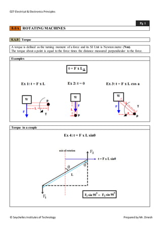
  • 1. 027 Electrical & Electronics Principles Pg 1 8.0A ROTATING MACHINES 8.A.0 Torque A torque is defined as the turning moment of a force and its SI Unit is Newton metre (Nm). The torque about a point is equal to the force times the distance measured perpendicular to the force. Examples Torque in a couple Ex 4: t = F x L sinθ © Seychelles Institutes of Technology Prepared by Mr. Dinesh
  • 2. 027 Electrical & Electronics Principles Pg 2 8.0A ROTATING MACHINES 8.A.1 Torque on a coil in a magnetic field Fig 1 Fig 1 (a) is the field between two magnets, (b) the field due to a current in a straight wire and (c) the resulting field if they are put together. This last field is known as the "catapult" field because it tends to catapult the wire out of the field in the direction shown by the arrow. Fig 2 Fig 2(a) show If a coil carrying a current is placed in a magnetic field it will experience a force on two of its sides in such a way as to make the coil rotate. Fig 2(b) shows coil will rotate from the 'double catapult' field diagram. Since the current moves along the two opposite sides of the coil in opposite directions the two sides receive a force in opposite directions also, thus turning the coil. © Seychelles Institutes of Technology Prepared by Mr. Dinesh
  • 3. 027 Electrical & Electronics Principles Pg 3 8.0A ROTATING MACHINES 8.A.2 Torque on a current carrying conductor Consider a rectangular coil in Fig 3 when the plane of the coil is lying along the field lines (θ = 90o) Where, τ = torque (Nm) L = length (m) W = width (m) B = magnetic field (Wb) I = current (A) Fig 3 τ = F x perpendicular distance τ = F x W = BIL x W = BI(LW) τ = BIA © Seychelles Institutes of Technology Prepared by Mr. Dinesh
  • 4. 027 Electrical & Electronics Principles Pg 4 8.0A ROTATING MACHINES Consider a number of rectangular coil in fig 4 when the plane of the coil is rotating along the field lines Where, τ = torque (Nm) L = length (m) W = width (m) d = perpendicular distance (m) θ = angle (°) B = magnetic field (Wb) I = current (A) N = number of turns Fig 4 τ = F x perpendicular distance τ = F x d = BILN x Wsinθ = BI(LW)Nsinθ τ = BIANsinθ © Seychelles Institutes of Technology Prepared by Mr. Dinesh
  • 5. 027 Electrical & Electronics Principles Pg 5 8.0A ROTATING MACHINES 8.A.3 Solved work examples on “torque on a current carrying conductor” Work example 1 Calculate the torque needed to hold a coil of 20 turns and area 8cm2 at an angle of 60o to a magnetic field of flux density 0.1T if the coil carries a current of 0.5 A. Solution Torque, τ = BANIsinθ = 0.1x20x8x10-4sin 60° τ = 8x10⁻⁴ Nm Work example 2 a) What is the maximum torque on a 150-turn square loop of wire 18.0 cm on a side that carries a 50.0A current in a 1.60-T field? b) What is the torque when θ is 10.9°? Solution a) Maximum torque, τ = BANIsinθ = 1.60x150x0.0182 x50.0sin 90° τ = b) When θ is 10.9°, τ = BANIsinθ = 1.60x150x0.182 x50.0sin 10.9° τ = © Seychelles Institutes of Technology Prepared by Mr. Dinesh
  • 6. 027 Electrical & Electronics Principles Pg 6 8.0A ROTATING MACHINES 8.A.4 E.m.f. induced in a straight conductor in a uniform magnetic field When a straight conductor is moved through a magnetic field an e.m.f. is induced between its ends. This movement must be in such a direction that the conductor cuts through the lines of magnetic flux, and will be a maximum when it moves at right angles to the field (Fig 5). Where, E = e.m.f. induced (V) L = length (m) B = magnetic field (Wb) v = velocity (m/s) Fig 5 If the conductor moves with velocity v at right angles to the field then the flux cut per second will be BvL (since the conductor will sweep out an area vL every second). But the rate of cutting flux is equal to the e.m.f. induced in the conductor. Therefore E = BLv © Seychelles Institutes of Technology Prepared by Mr. Dinesh
  • 7. 027 Electrical & Electronics Principles Pg 7 8.0A ROTATING MACHINES If the conductor cuts through the flux at an angle θ ( in Fig 5), where θ is the angle between the magnetic field and the direction of motion, the equation becomes E = BLv sinθ 8.A.5 Solved work examples on Emf induced on a straight conductor Work example 1 Calculate a) The e.m.f. generated between the wing tips of an aircraft that is flying horizontally at 200 ms-1 in a region where the vertical component of the Earth's magnetic field is 4.0x10⁻⁵ T, if the aircraft has a wingspan of 25 m. b) What will be the e.m.f. if the θ = 30°. Solution a) Maximum e.m.f., E = BLvsinθ = 4.0x10-5x25x200 sin 90° E = 0.2V b) When θ is 30°, E = BANIsinθ = 4.0x10-5x150x200 sin 30° E = 0.1V © Seychelles Institutes of Technology Prepared by Mr. Dinesh
  • 8. 027 Electrical & Electronics Principles Pg 8 8.0A ROTATING MACHINES 8.A.4 Emf induced in a straight conductor rotating in a uniform magnetic field Consider the Fig 6, a diagram of an electrical generator. A generator with a single rectangular coil rotated at constant angular velocity in a uniform magnetic field produces an e.m.f. that varies sinusoidally in time. Note the generator is similar to a motor, except the shaft is rotated to produce a current rather than the other way around. Where, E = e.m.f. induced (V) L = length (m) B = magnetic field (Wb) v = velocity (m/s) θ = angle (°) ω = angular velocity (rad/s) Fig 6 The induced e.m.f. by considering only the side wires. Motional e.m.f. is given to be E = BLv, where the velocity v is perpendicular to the magnetic field B Here, the velocity is at an angle θ with B, so that its component perpendicular to B is vsinθ. Thus in this case the e.m.f. induced on each side is E = BLvsinθ, and they are in the same direction. The total EMF ε around the loop is then: E = 2BLvsinθ This expression is valid, but it does not give EMF as a function of time. © Seychelles Institutes of Technology Prepared by Mr. Dinesh
  • 9. 027 Electrical & Electronics Principles Pg 9 8.0A ROTATING MACHINES To find the time dependence of EMF, we assume the coil rotates at a constant angular velocity ω. The angle θ is related to angular velocity by θ = ωt, so that: E = 2Blvsinωt Now, linear velocity v is related to angular velocity by v = rω. Here r = w/2, so that v = (w/2)ω, and: E = 2BLw2ωsinωt E = (Lw)Bωsinωt Noting that the area of the loop is A = Lw, and allowing for N loops, we find that: E = NABω sinωt The maximum value of the e.m.f (Emax) is when θ (= ωt) = 90o, is given by E = NABω © Seychelles Institutes of Technology Prepared by Mr. Dinesh
  • 10. 027 Electrical & Electronics Principles Pg 10 8.0A ROTATING MACHINES 8.A.5 Solved work examples on Emf induced in a rotating in a uniform magnetic field Work example 1 Calculate a) The maximum value of the e.m.f generated in a coil with 200 turns and of area 10 cm2 rotating at 60 radians per second in a field of flux density 0.1 T. b) The e.m.f. when θ = 60o Solution a) Maximum e.m.f., E = BANωsinθ = 0.1x10-5x200x60 sin 90° E = 1.2V b) When θ is 30°, E = BANωsinθ = 0.1x10-5x200x60 sin 60° E = 1.04V Notice the use of radians per second. © Seychelles Institutes of Technology Prepared by Mr. Dinesh
  • 11. 027 Electrical & Electronics Principles Pg 11 8.0A ROTATING MACHINES 8.A.6 Power generated in rotating machines The linear motion of a conductor through a magnetic field, the mechanical power supplied is equal to the electrical power generated. 8.1.7 Derivation of power in rotating machines For a rotating object, the linear distance covered at the circumference of rotation is the product of the radius with the angle covered. That is: Linear distance = radius × angular distance. By definition, Linear distance = linear speed × time = radius × angular speed × time. By the definition of torque: Torque = radius × force. These two values can be substituted into the definition of power: Power = Force × Linear distance Time = (Torque⁄Radius)× (Radius × Angular speed) Time = Torque × Angular speed or Power = Torque × 2π × Rotational speed Where, Torque, τ (N/m) Angular speed, ω (rad/s) Rotational speed, n (rev/s) Radius, r (m) © Seychelles Institutes of Technology Prepared by Mr. Dinesh
  • 12. 027 Electrical & Electronics Principles Pg 12 8.0A ROTATING MACHINES Rotational power is given by, P = ω. τ Where, ω, angular velocity is defined as the rate of change of angular displacement which specifies the angular speed (rotational speed) of an object and the axis about which the object is rotating. Measured in radian per second (rad/s) τ, torque is defined as the moment of force is the tendency of a force to rotate an object about an axis. Measured in newton per metre (N/m) P, In rotational systems, power is defined as the product of the torque and angular velocity. Measured in watts (W) 8.A.8 Power efficiency Power efficiency is defined as the ratio of output power divided by input power. Ƞ = 100% · Where, ƞ = efficiency (%) Pout = output power (W) Pin = input power (W) 퐏퐨퐮퐭 퐏퐢퐧 © Seychelles Institutes of Technology Prepared by Mr. Dinesh
  • 13. 027 Electrical & Electronics Principles Pg 13 8.0A ROTATING MACHINES 8.A.9 Solved work examples on power in rotating machines Work example 1 A machine is rotating with speed of 3000 rev/min (rpm) consumes 5kW. Calculate the torque of the shaft. Solution Given, ƞ = 3000 rpm P = 5kW τ = ? Using τ = 퐏/ퟐ훑ƞ = (5 × 1000) ÷ [(2π × 3000 60 )] τ = 15.9 N/m Work example 2 An electric motor has an input power consumption of 50 watts. The motor was activated for 60 seconds and produced work of 2970 joules. Find the efficiency of motor? Solution Given, Pin = 50W t = 60s E = 2970J ƞ = ? Pout = ? Using Pout = E / t = 2970/60 Pout = 49.45W Now ƞ = ퟏퟎퟎ% × 퐏퐨퐮퐭 / 퐏퐢퐧 = ퟏퟎퟎ × (ퟒퟗ. ퟗퟓ/ퟓퟎ) ƞ = ퟗퟗ% © Seychelles Institutes of Technology Prepared by Mr. Dinesh