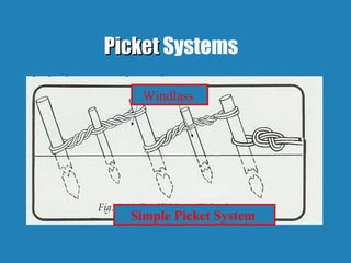
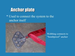
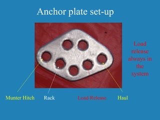
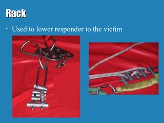
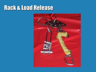
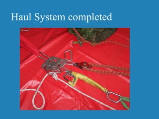
Rope Rescue
Set-Up Review
Newport Fire Department
Overview
1. Anchoring/Picket System
2. Anchor Plate
Anchoring PrincipalsAnchoring Principals
1.1. Anchors are the foundation of the rope rescueAnchors are the foundation of the rope rescue
system.system.
2.2. The actual physical strength and capacity ofThe actual physical strength and capacity of
an anchor is generally unknown. What wean anchor is generally unknown. What we
determine to be “bombproof” is really adetermine to be “bombproof” is really a
judgment based on knowledge, training, andjudgment based on knowledge, training, and
experience.experience.
Good AnchorsGood Anchors
1. Structural Steel (Properly1. Structural Steel (Properly
connected to a structure)connected to a structure)
2. Reinforced Concrete2. Reinforced Concrete
3. Bulk Masonry3. Bulk Masonry
4. Heavy Machinery4. Heavy Machinery
(Cranes, Bulldozer, etc.)(Cranes, Bulldozer, etc.)
5. Fire Apparatus5. Fire Apparatus
6. Natural Anchors6. Natural Anchors
(Big *#^&%ing Rock(Big *#^&%ing Rock
/ Big LIVE rooted/ Big LIVE rooted
tree)tree)
7. HVAC Units (If7. HVAC Units (If
properly secured toproperly secured to
the structure)the structure)
8. Pickets8. Pickets
Bad AnchorsBad Anchors
1.1. Insulated PipeInsulated Pipe
2.2. Cast Iron Pipe (StandCast Iron Pipe (Stand
pipes and Sprinkler risers)pipes and Sprinkler risers)
3.3. Masonry Without BulkMasonry Without Bulk
4.4. Concrete Block WallsConcrete Block Walls
5.5. ChimneysChimneys
6.6. Exhaust DuctsExhaust Ducts
1.1. Hand RailsHand Rails
2.2. Stair TreadsStair Treads
3.3. Ladder RungsLadder Rungs
4.4. Wood FramedWood Framed
WallsWalls
5.5. Corroded MetalCorroded Metal
6.6. Round RocksRound Rocks
7.7. Trees with shallowTrees with shallow
rootsroots
Self-EqualizingSelf-Equalizing
Helps to transfer weight of the load.Helps to transfer weight of the load.
If one anchor fails thereIf one anchor fails there willwill be a shockbe a shock
load.load.
Always try to keep the “self-equalizer” asAlways try to keep the “self-equalizer” as
short as possible keeping in mind theshort as possible keeping in mind the
“critical angles”.“critical angles”.
Self-Equalizing
Twist in line prevents webbing from sliding through
Self-EqualizingSelf-Equalizing
Self-Equalizer
Angle Leg Tension
170° 1150 %
150° 200 %
120° 100 %
90° 70 %
0° 50 %
Critical AnglesCritical Angles
PicketPicket Systems
Simple Picket System
Windlass
Picket Systems
1. Picket systems are usually made up of three or1. Picket systems are usually made up of three or
more evenly spaced stakes driven into themore evenly spaced stakes driven into the
ground or snow.ground or snow.
2. The stakes should be positioned in a straight2. The stakes should be positioned in a straight
line away from the intended rappelling orline away from the intended rappelling or
lowering point.lowering point.
3. They should be spaced approximately one3. They should be spaced approximately one
stake length apart.stake length apart.
Picket Systems
4. After the stakes are driven to the ground,4. After the stakes are driven to the ground,
secure a length of rope or webbing to thesecure a length of rope or webbing to the
base of the picket farthest from the loadbase of the picket farthest from the load
and then take 3 to 6 turns around the top ofand then take 3 to 6 turns around the top of
the next closest picket, ending with a clovethe next closest picket, ending with a clove
hitch on either picket.hitch on either picket.
5. Repeat this lashing from the base of each5. Repeat this lashing from the base of each
picket to the top of the next closest picketpicket to the top of the next closest picket
to the load.to the load.
Picket SystemsPicket Systems
6. Next place a shorter stake (a CROW-BAR works6. Next place a shorter stake (a CROW-BAR works
well) between the the lashings and twist until all ofwell) between the the lashings and twist until all of
the slack is out and you are starting to put tension onthe slack is out and you are starting to put tension on
the forward picket. (Windlass)the forward picket. (Windlass)
7. Repeat the tensioning process to subsequent7. Repeat the tensioning process to subsequent
lashings, working toward the load.lashings, working toward the load.
8. The short stakes used for tensioning should be8. The short stakes used for tensioning should be
driven into the ground a short distance to securedriven into the ground a short distance to secure
them.them.
Anchor plateAnchor plate
* Used to connect the system to the
anchor itself
Webbing connects to
“bombproof” anchor
Anchor plate set-up
Load
release
always in
the
system
Munter Hitch Rack Load Release Haul
RackRack
• Used to lower responder to the victim
Load ReleaseLoad Release
• Used to release weight of rescuer/victim when
prussik knots “lock” onto safety rope
• Always in the system (safety)
Rack & Load ReleaseRack & Load Release
Prussick linesPrussick lines
• Attach from safety line to load release (always connected in
system
Line connects to rescuer using
“Figure 8”
Completed Lowering Setup
Raise VictimRaise Victim
• Remove the rack from the system
• Add a munter hitch to the system
(opposite side of pulley)
• Add the haul (5:1) pulley system
Munter Hitch
• Add to the carabineer (far left side on
anchor plate)
1
2
3
Munter – second view
3
Haul System completed
Practical Application
Go put it all together…

Rope rescue set up

  • 1.
  • 2.
  • 3.
    Anchoring PrincipalsAnchoring Principals 1.1.Anchors are the foundation of the rope rescueAnchors are the foundation of the rope rescue system.system. 2.2. The actual physical strength and capacity ofThe actual physical strength and capacity of an anchor is generally unknown. What wean anchor is generally unknown. What we determine to be “bombproof” is really adetermine to be “bombproof” is really a judgment based on knowledge, training, andjudgment based on knowledge, training, and experience.experience.
  • 4.
    Good AnchorsGood Anchors 1.Structural Steel (Properly1. Structural Steel (Properly connected to a structure)connected to a structure) 2. Reinforced Concrete2. Reinforced Concrete 3. Bulk Masonry3. Bulk Masonry 4. Heavy Machinery4. Heavy Machinery (Cranes, Bulldozer, etc.)(Cranes, Bulldozer, etc.) 5. Fire Apparatus5. Fire Apparatus 6. Natural Anchors6. Natural Anchors (Big *#^&%ing Rock(Big *#^&%ing Rock / Big LIVE rooted/ Big LIVE rooted tree)tree) 7. HVAC Units (If7. HVAC Units (If properly secured toproperly secured to the structure)the structure) 8. Pickets8. Pickets
  • 5.
    Bad AnchorsBad Anchors 1.1.Insulated PipeInsulated Pipe 2.2. Cast Iron Pipe (StandCast Iron Pipe (Stand pipes and Sprinkler risers)pipes and Sprinkler risers) 3.3. Masonry Without BulkMasonry Without Bulk 4.4. Concrete Block WallsConcrete Block Walls 5.5. ChimneysChimneys 6.6. Exhaust DuctsExhaust Ducts 1.1. Hand RailsHand Rails 2.2. Stair TreadsStair Treads 3.3. Ladder RungsLadder Rungs 4.4. Wood FramedWood Framed WallsWalls 5.5. Corroded MetalCorroded Metal 6.6. Round RocksRound Rocks 7.7. Trees with shallowTrees with shallow rootsroots
  • 6.
    Self-EqualizingSelf-Equalizing Helps to transferweight of the load.Helps to transfer weight of the load. If one anchor fails thereIf one anchor fails there willwill be a shockbe a shock load.load. Always try to keep the “self-equalizer” asAlways try to keep the “self-equalizer” as short as possible keeping in mind theshort as possible keeping in mind the “critical angles”.“critical angles”.
  • 7.
    Self-Equalizing Twist in lineprevents webbing from sliding through
  • 8.
  • 9.
    Angle Leg Tension 170°1150 % 150° 200 % 120° 100 % 90° 70 % 0° 50 % Critical AnglesCritical Angles
  • 10.
  • 11.
    Picket Systems 1. Picketsystems are usually made up of three or1. Picket systems are usually made up of three or more evenly spaced stakes driven into themore evenly spaced stakes driven into the ground or snow.ground or snow. 2. The stakes should be positioned in a straight2. The stakes should be positioned in a straight line away from the intended rappelling orline away from the intended rappelling or lowering point.lowering point. 3. They should be spaced approximately one3. They should be spaced approximately one stake length apart.stake length apart.
  • 12.
    Picket Systems 4. Afterthe stakes are driven to the ground,4. After the stakes are driven to the ground, secure a length of rope or webbing to thesecure a length of rope or webbing to the base of the picket farthest from the loadbase of the picket farthest from the load and then take 3 to 6 turns around the top ofand then take 3 to 6 turns around the top of the next closest picket, ending with a clovethe next closest picket, ending with a clove hitch on either picket.hitch on either picket. 5. Repeat this lashing from the base of each5. Repeat this lashing from the base of each picket to the top of the next closest picketpicket to the top of the next closest picket to the load.to the load.
  • 13.
    Picket SystemsPicket Systems 6.Next place a shorter stake (a CROW-BAR works6. Next place a shorter stake (a CROW-BAR works well) between the the lashings and twist until all ofwell) between the the lashings and twist until all of the slack is out and you are starting to put tension onthe slack is out and you are starting to put tension on the forward picket. (Windlass)the forward picket. (Windlass) 7. Repeat the tensioning process to subsequent7. Repeat the tensioning process to subsequent lashings, working toward the load.lashings, working toward the load. 8. The short stakes used for tensioning should be8. The short stakes used for tensioning should be driven into the ground a short distance to securedriven into the ground a short distance to secure them.them.
  • 14.
    Anchor plateAnchor plate *Used to connect the system to the anchor itself Webbing connects to “bombproof” anchor
  • 15.
    Anchor plate set-up Load release alwaysin the system Munter Hitch Rack Load Release Haul
  • 16.
    RackRack • Used tolower responder to the victim
  • 17.
    Load ReleaseLoad Release •Used to release weight of rescuer/victim when prussik knots “lock” onto safety rope • Always in the system (safety)
  • 18.
    Rack & LoadReleaseRack & Load Release
  • 19.
    Prussick linesPrussick lines •Attach from safety line to load release (always connected in system Line connects to rescuer using “Figure 8”
  • 20.
  • 21.
    Raise VictimRaise Victim •Remove the rack from the system • Add a munter hitch to the system (opposite side of pulley) • Add the haul (5:1) pulley system
  • 22.
    Munter Hitch • Addto the carabineer (far left side on anchor plate) 1 2 3
  • 23.
  • 24.
  • 25.
    Practical Application Go putit all together…