"Federated learning: out of reach no matter how close",Oleksandr Lapshyn
Mounting Card Hosts DZCANTU Servo Drives
1. Mounting Card MC1XDZPC01
Description
Drive Compatibility
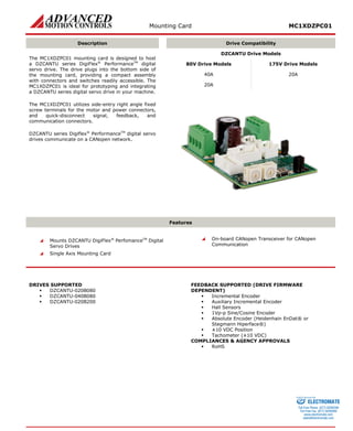
The MC1XDZPC01 mounting card is designed to host a DZCANTU series DigiFlex® PerformanceTM digital servo drive. The drive plugs into the bottom side of the mounting card, providing a compact assembly with connectors and switches readily accessible. The MC1XDZPC01 is ideal for prototyping and integrating a DZCANTU series digital servo drive in your machine.
The MC1XDZPC01 utilizes side-entry right angle fixed screw terminals for the motor and power connectors, and quick-disconnect signal, feedback, and communication connectors.
DZCANTU series Digiflex® PerformanceTM digital servo drives communicate on a CANopen network.
DZCANTU Drive Models
80V Drive Models
175V Drive Models
40A
20A
20A
Features
Mounts DZCANTU DigiFlex® PerfomanceTM Digital Servo Drives
Single Axis Mounting Card
On-board CANopen Transceiver for CANopen Communication
DRIVES SUPPORTED
DZCANTU-020B080
DZCANTU-040B080
DZCANTU-020B200
FEEDBACK SUPPORTED (DRIVE FIRMWARE DEPENDENT)
Incremental Encoder
Auxiliary Incremental Encoder
Hall Sensors
1Vp-p Sine/Cosine Encoder
Absolute Encoder (Heidenhain EnDat® or Stegmann Hiperface®)
±10 VDC Position
Tachometer (±10 VDC)
COMPLIANCES & AGENCY APPROVALS
RoHS
ELECTROMATE
Toll Free Phone (877) SERVO98
Toll Free Fax (877) SERV099
www.electromate.com
sales@electromate.com
Sold & Serviced By:
2. Mounting Card MC1XDZPC01
BLOCK DIAGRAM & SPECIFICATION SUMMARY
MOT ENC A,B,I + / SIN + / COS + MOT ENC A,B,I –/ SIN -/ COS - HALL A,B,C+ HIGH VOLTAGEMOTOR AMOTOR BMOTOR CAUX SUPPLYMC1XDZPC01 MOUNTING CARDGND I/O InterfaceI/O Interface DriveLogicCANopen Interface6.7k6.7kUSB Interface Motor Feedback 20k+5VPower StageLogic Power20k+5VPAI-1 + (REF+) PAI-1 –(REF–) MOTOR THERMISTORGNDGP PDO-1,2,3,4,5GP PDI-1,2,3+HS PDI-4,5-HS PDI-4,5CAN_HIGHDATA- DATA+ USB GNDCAN_LOWVBUS I/O Connector DATA,CLOCK+ DATA,CLOCK- AUX ENC+ / PDI-6,7,8+ AUX ENC-/ PDI-6,7,8- GND Aux FeedbackConnectorCANopenConnectorUSBConnectorMotor Power ConnectorPower Connector DZCANTU SERVO DRIVE Feedback Connector
Mechanical Specifications
Mounting Signal Connector: Mates Directly to Drive
96-port, 1.27mm spaced, dual-row socket
Mounting Power Connector: Mates Directly to Drive
50-pin, 2.0mm spaced, dual-row socket
Motor Power Connector: P1
4-port screw terminal
Power Connector: P2
4-port screw terminal
CANopen Communication Connector: P5*
8-pin, dual-row, 2.00 mm spaced plug terminal, vertical mount
USB Connector: P6
5-pin, Mini USB B Type port
I/O Connector: P7*
20-pin, dual-row, 2.00 mm spaced plug terminal, vertical mount
Auxiliary Feedback Connector: P8*
10-pin, dual-row, 2.00 mm spaced plug terminal, vertical mount
Feedback Connector: P9*
18-pin, dual-row, 2.00 mm spaced plug terminal, vertical mount
Size (L x W x H) / mm (in)
63.5 x 88.9 x 26.3 (2.5 x 3.5 x 1.0)
Weight / g (oz)
68 (2.4)
*Mating Connector Kit
Mating connector housing and crimp pins can be ordered as a kit using ADVANCED Motion Controls part number KC-MC1XDZP01. This includes mating connector housing and crimp style contacts for the I/O, Feedback, Auxiliary Feedback, and Communication connectors. The recommended tool for crimping the contacts is Molex part number 63811-6300. ELECTROMATE
Toll Free Phone (877) SERVO98
Toll Free Fax (877) SERV099
www.electromate.com
sales@electromate.com
Sold & Serviced By:
3. Mounting Card MC1XDZPC01
PIN FUNCTIONS
Mounting Signal Connector
This connector mates directly to the drive. For pin functions refer to the drive datasheet.
Mounting Power Connector
This connector mates directly to the drive. For pin functions refer to the drive datasheet.
P1 – Motor Power Connector
Pin
Name
Description / Notes
I/O
1
MOTOR C
Motor Phase C
O
2
MOTOR B
Motor Phase B
O
3
MOTOR A
Motor Phase A
O
4
CHASSIS
Shield Connection
-
P2 - Power Connector
Pin
Name
Description / Notes
I/O
1
CHASSIS
Shield Connection
-
2
AUX SUPPLY
Logic Supply
I
3
GND
Ground
GND
4
HV
DC Power Supply
I
P5 – CANopen Communication Connector
Pin
Name
Description / Notes
I/O
1
CAN_H
CAN_H bus line (dominant high)
I/O
2
CAN_H
I/O
3
CAN_L
CAN_L bus line (dominant low)
I/O
4
CAN_L
I/O
5
GND
Ground
GND
6
GND
GND
7
RESERVED
Reserved
-
8
RESERVED
-
P6 - USB Communication Connector
Pin
Name
Description / Notes
I/O
1
VBUS
Supply Voltage
O
2
DATA -
USB Data -
I/O
3
DATA +
USB Data +
I/O
4
RESERVED
Reserved
-
5
GND
USB Ground
UGND
ELECTROMATE
Toll Free Phone (877) SERVO98
Toll Free Fax (877) SERV099
www.electromate.com
sales@electromate.com
Sold & Serviced By:
4. Mounting Card MC1XDZPC01
P7 – I/O Connector
Pin
Name
Description
I/O
1
CHASSIS
Shield Connection
-
2
RESERVED
Reserved
-
3
PDI-1
Programmable Digital Input
I
4
PDI-4+
High Speed Differential Programmable Digital Input
I
5
PDI-2
Programmable Digital Input
I
6
PDI-4-
High Speed Differential Programmable Digital Input
I
7
PDI-3
Programmable Digital Input
I
8
PDI-5+
High Speed Differential Programmable Digital Input
I
9
RESERVED
Reserved
-
10
PDI-5-
High Speed Differential Programmable Digital Input
I
11
PDO-1
Programmable Digital Output
O
12
RESERVED
Reserved
-
13
PDO-2
Programmable Digital Output
O
14
+5V OUT
+5V Output from Logic Supply
O
15
PDO-3
Programmable Digital Output
O
16
GND
Ground
GND
17
PDO-4
Programmable Digital Output
O
18
PAI-1+
Differential Programmable Analog Input or Reference Signal Input (12-bit resolution)
I
19
PDO-5
Programmable Digital Output
O
20
PAI-1-
Differential Programmable Analog Input or Reference Signal Input (12-bit resolution)
I
P8 – Auxiliary Feedback Connector
Pin
Name
Description
I/O
1
CHASSIS
Shield Connection
-
2
RESERVED
Reserved
-
3
AUX ENC I+
Auxiliary Incremental Encoder Channel I or Differential Programmable Digital Input 8
I
4
AUX ENC A+
Auxiliary Incremental Encoder Channel A or Differential Programmable Digital Input 6
I
5
AUX ENC I-
Auxiliary Incremental Encoder Channel I or Differential Programmable Digital Input 8
I
6
AUX ENC A-
Auxiliary Incremental Encoder Channel A or Differential Programmable Digital Input 6
I
7
+5V USER
+5V User Supply Output (current shared with pin P9-17)
O
8
AUX ENC B+
Auxiliary Incremental Encoder Channel B or Differential Programmable Digital Input 7
I
9
GND
Ground
GND
10
AUX ENC B-
Auxiliary Incremental Encoder Channel B or Differential Programmable Digital Input 7
I
P9 – Feedback Connector*
Pin
Incremental Encoder
Absolute Encoder
1Vp-p Sin/Cos Encoder
Description / Notes
I/O
1
CHASSIS
CHASSIS
CHASSIS
Shield Connection
-
2
RESERVED
RESERVED
RESERVED
Reserved
-
3
MOT ENC I+
RESERVED
RESERVED
Differential Encoder Index
I
4
MOT ENC A+
SIN+
SIN+
Differential Encoder A / Differential Sine Input
I
5
MOT ENC I-
RESERVED
RESERVED
Differential Encoder Index
I
6
MOT ENC A-
SIN-
SIN-
Differential Encoder A / Differential Sine Input
I
7
HALL A
RESERVED
HALL A
Commutation sensor input.
I
8
MOT ENC B+
COS+
COS+
Differential Encoder B/ Differential Cosine Input
I
9
HALL B
RESERVED
HALL B
Commutation sensor input.
I
10
MOT ENC B-
COS-
COS-
Differential Encoder B/ Differential Cosine Input
I
11
HALL C
RESERVED
HALL C
Commutation sensor input.
I
12
RESERVED
CLK+
RESERVED
Differential Clock Line
-
13
MOTOR THERMISTOR
MOTOR THERMISTOR
MOTOR THERMISTOR
Motor Thermal Protection
I/O
14
RESERVED
CLK-
RESERVED
Differential Clock Line
I/O
15
+5V USER
+5V USER
+5V USER
+5V User Supply Output (current shared with pin P8-7)
I/O
16
RESERVED
DATA+
RESERVED
Differential Data Line
I/O
17
GND
GND
GND
Ground
GND
18
RESERVED
DATA-
RESERVED
Differential Data Line
I/O
*Note: Feedback supported (Incremental Encoder, Absolute Sin/Cos Encoder, or 1Vp-p Sin/Cos Encoder) will be dependent on drive firmware.
ELECTROMATE
Toll Free Phone (877) SERVO98
Toll Free Fax (877) SERV099
www.electromate.com
sales@electromate.com
Sold & Serviced By:
5. Mounting Card MC1XDZPC01
BOARD CONFIGURATION
CANopen Node ID Switches
Switch Diagram
Description
0123 456789ABCDEF 0123 45 6789ABCDEF SW0SW1
Hexadecimal switch settings correspond to the CANopen Node ID.
Allowable CANopen Node ID range is 001 - 127.
SW1
SW0
Node ID
0
1
001
0
2
002
…
…
…
7
D
125
7
E
126
7
F
127
CANopen Bit Rate Jumpers
The CANopen bit rate is controlled by jumpers JF12 and JF13, located near the USB communication connector, P6. Use the table below to configure the bit rate.
Bit Rate (kbits/sec)
JF12
JF13
Load from non-volatile memory
Not Installed
Not Installed
500
Installed
Not Installed
250
Not Installed
Installed
125
Installed
Installed
CANopen Termination Node Jumper
CANopen bus termination is controlled by jumper JF1. The last device in a CAN network requires a termination resistor across the CAN_H and CAN_L lines. JF1 is located near the CANopen communication connector, P5.
CANopen Termination
JF1
Non-terminating Node
Not Installed
Terminating Node
Installed
LED Functions
The MC1XDZPC01 contains LEDs that indicate DC Power Supply status, Logic Power Supply status, and the drive Bridge status. The Power LED (P) will light up green when power is applied to P2-Power Connector, and the Logic LED (L) will light up green when the Logic Power is applied to P3-Auxiliary Logic Connector. The Bridge Status LED (STS) indicates the servo drive’s power bridge state, and will be green when the drive is enabled, and red when the drive is in a fault state.
Mounting Configuration
ELECTROMATE
Toll Free Phone (877) SERVO98
Toll Free Fax (877) SERV099
www.electromate.com
sales@electromate.com
Sold & Serviced By:
6. Mounting Card MC1XDZPC01
CONNECTOR INFORMATION
Mounting Signal Connector
Connector Information
96-pin, 1.27 mm spaced, dual-row socket
Mating Connector Example
No Mating Connector Required. Mate directly to drive
Mounting Power Connector
Connector Information
50-pin, 2.0 mm spaced, dual-row socket
Mating Connector Example
No Mating Connector Required. Mate directly to drive
P1 – Motor Power Connector
Connector Information
4-port screw terminal
Mating Connector
Details
Not Applicable
Included with Card
Not Applicable
CHASSIS4MOTOR C3MOTOR B2MOTOR A1
P2 – Power Connector
Connector Information
4-port screw terminal
Mating Connector
Details
Not Applicable
Included with Card
Not Applicable
HV4GND3AUX SUPPLY2CHASSIS1
P5 – CANopen Communication Connector
Connector Information
8-pin, dual-row, 2.00 mm spaced plug terminal, vertical mount
Mating Connector
Details
Molex: P/N 51353-0800 (housing); 56134-9100 (contacts)
Included with Card
No
1CAN_H3CAN_L2CAN_H4CAN_L8RESERVED6GND7RESERVED5GND
ELECTROMATE
Toll Free Phone (877) SERVO98
Toll Free Fax (877) SERV099
www.electromate.com
sales@electromate.com
Sold & Serviced By:
7. Mounting Card MC1XDZPC01
P6 – USB Connector
Connector Information
5-pin, Mini USB B Type port
Mating Connector
Details
TYCO: 1496476-3 (2-meter STD-A to MINI-B ASSY)
Included with Card
No
1VBUS2DATA - 3DATA + 4RESERVED5GND
P7 – I/O Connector
Connector Information
20-pin, dual-row, 2.00 mm spaced plug terminal, vertical mount
Mating Connector
Details
Molex: P/N 51353-2000 (housing); 56134-9100 (contacts)
Included with Card
No
1CHASSIS3PDI-15PDI-27PDI-39RESERVED2RESERVED4PDI-4+ 6PDI-4- 8PDI-5+ 10PDI-5- 20PAI-1- 18PAI-1+ 16GND14+5V OUT12RESERVED19PDO-517PDO-415PDO-313PDO-211PDO-1
P8 – Auxiliary Feedback Connector
Connector Information
10-pin, dual-row, 2.00 mm spaced plug terminal, vertical mount
Mating Connector
Details
Molex: P/N 51353-1000 (housing); 56134-9100 (contacts)
Included with Card
No
1CHASSIS3AUX ENC I+ 5AUX ENC I- 2RESERVED4AUX ENC A+ 6AUX ENC A- 10AUX ENC B- 8AUX ENC B+ 9GND7+5V USER
ELECTROMATE
Toll Free Phone (877) SERVO98
Toll Free Fax (877) SERV099
www.electromate.com
sales@electromate.com
Sold & Serviced By:
10. Mounting Card MC1XDZPC01
MOUNTING CONFIGURATION
Note that a DZCANTU servo drive plugs into the MC1XDZPC01 from the underside of the mounting card to allow easy access to the mounting card switches and connectors. The drive and mounting card assembly can be secured to a panel or heatsink through the mounting holes in the drive baseplate and the sides of the mounting card.
The mounting card chassis should be secured to the drive baseplate by using the two spacers included with the MC1XDZPC01 between the MC1XDZPC01 mounting holes and the drive baseplate as shown in the below image.
ELECTROMATE
Toll Free Phone (877) SERVO98
Toll Free Fax (877) SERV099
www.electromate.com
sales@electromate.com
Sold & Serviced By:
11. Mounting Card MC1XDZPC01
PART NUMBERING INFORMATION
XDrive Type IndicatorDZP: DZ DigiFlex PerformanceAxisNumber of axes supportedProduct TypeMC indicates mounting cardSeriesMounting card seriesMC1DZP01CCommunication TypeE:EtherCATC:CANopen
DigiFlex® Performance™ series of products are available in many configurations. All models listed in the selection tables of the website are readily available, standard product offerings.
ADVANCED Motion Controls also has the capability to promptly develop and deliver specified products for OEMs with volume requests. Our Applications and Engineering Departments will work closely with your design team through all stages of development in order to provide the best servo drive solution for your system. Equipped with on-site manufacturing for quick- turn customs capabilities, ADVANCED Motion Controls utilizes our years of engineering and manufacturing expertise to decrease your costs and time-to-market while increasing system quality and reliability.
Examples of Customized Products
Optimized Footprint
Tailored Project File
Private Label Software
Silkscreen Branding
OEM Specified Connectors
Optimized Base Plate
No Outer Case
Increased Current Limits
Increased Current Resolution
Increased Voltage Range
Increased Temperature Range
Conformal Coating
Custom Control Interface
Multi-Axis Configurations
Integrated System I/O
Reduced Profile Size and Weight
Feel free to contact Applications Engineering for further information and details.
All specifications in this document are subject to change without written notice. Actual product may differ from pictures provided in this document.
ELECTROMATE
Toll Free Phone (877) SERVO98
Toll Free Fax (877) SERV099
www.electromate.com
sales@electromate.com
Sold & Serviced By: