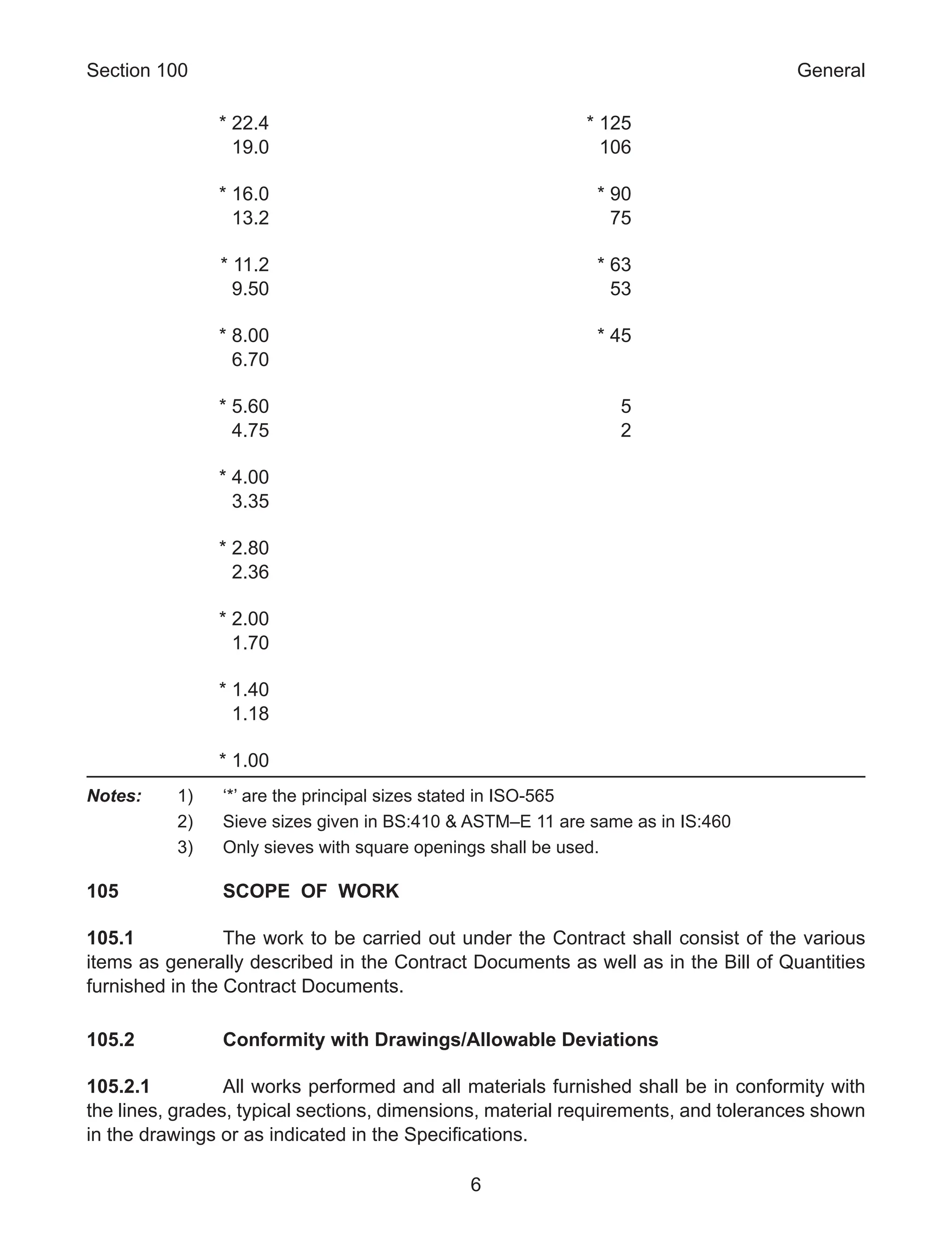
This document provides the fifth revision of the specifications for road and bridge works published by the Indian Roads Congress on behalf of the Ministry of Road Transport and Highways in India. Some key changes in this revision include additions covering new materials and construction techniques for roads and bridges. The specifications cover various aspects of road and bridge construction including earthworks, pavements, drainage, concrete structures, and traffic management. It is intended to help achieve technical excellence and quality in major road projects being undertaken in India.
2. Ministry of Road Transport & Highways
Specifications for Road and Bridge Works
(Fifth Revision)
Published By the Indian Roads Congress,
on Behalf of the Govt. of India,
Ministry of Road Transport & Highways
Copies can be had from Indian Roads Congress,
Jamnagar House, Shahjahan Road, New Delhi &
Sector 6, R.K. Puram, Kama Koti Marg, New Delhi
Price Rs. 3,000/-
Plus packing & postage charges
3. First Published : April, 1973
Reprinted : November, 1975
Reprinted : May, 1978
Reprinted : September, 1981
Reprinted : October, 1983
Reprinted : April, 1986
Second Revision : February, 1988
Reprinted : August, 1988
Reprinted : April, 1990
Reprinted : June, 1992
Reprinted : February, 1993
Reprinted : July, 1993
Third Revision : April, 1995
Reprinted : January, 1997 (Incorporates Corrigendum No.1 & 2 and
Col. 12 & 15 p. 662)
Reprinted : January, 1998
Reprinted : January, 1999
Reprinted : May, 1999
Reprinted : February, 2000
Reprinted : September, 2000 (Section 700 “Geosynthetics” Changed to
“Geosynthetics and Reinforced Earth”)
Fourth Revision : August, 2001
Reprinted : January, 2002
Reprinted : March, 2002
Reprinted : September 2002
Reprinted : November, 2002
Reprinted : March, 2003
Reprinted : June, 2003
Reprinted : July, 2003
Reprinted : December, 2003
Reprinted : May, 2004
Reprinted : September, 2004
Reprinted : April, 2005
Reprinted : October, 2005
Reprinted : March, 2006
Reprinted : September, 2006
Reprinted : March, 2007
Reprinted : August, 2007
Reprinted : February, 2008
Reprinted : August, 2008
Reprinted : November, 2008
Reprinted : March, 2009
Reprinted : June, 2009
Reprinted : December, 2009
Reprinted : March, 2010
Reprinted : July, 2010
Fifth Revision : April, 2013
(Rights of publication and Translation are reserved)
Printed at: India Offset Press, A-1 Mayapuri Ind. Area Phase-1 New Delhi-11064
(1000 copies)
4. PREFACE TO THE FIFTH REVISION
This edition of the Specifications for Road and Bridge Works marks the Fifth Revision. In
the last decade and a half, significant developments have taken place in the highways
sector. The massive National Highways Development Projects (NHDP) undertaken by the
Government of India is in progress involving execution of a large number of high value road
projects. These require adoption of latest international practices so as to achieve technical
execellence and the best quality. Concrete bridges have also undergone major changes with
deveopment of new structural forms, new methods of computer based analysis and design
and development of high strength materials, IRC:112 for concrete bridges based on the limit
state method has come into force. Over the past few years, many IRC codes have also been
completely revised necessitating extensive changes in the Ministry’s specifications for road
and bridge works.
Some of the important additions in this revision of Specifications for Road and Bridge Works
cover stone mastic asphalt, microsurfacing, sand asphalt base course, prefabricated vertical
drains (PVD), natural geo textiles, geo cells for use in base and sub base in pavement
and slope protection, variable message sign boards, soil nailing, cold applied retro-reflective
paints, audible and vibratory pavement markings, solar powered road markers, traffic
control & safety devices in construction zone, traffic impact attenuators and advance traffic
management system. Some of the new areas covered in bridges include high performance
concrete, HDPE sheathings, Pot-PTFE bearings, jack down method of well sinking, dynamic
testing of piles and mechanically woven wire crates for gabions.
The Fifth Revision of the Specifications for Road and Bridge Works is the result of the
concerted efforts of the officers of the Roads Wing and other professionals who contributed
to the drafting of this document. I wish to express my gratitude to all of them and the Indian
Roads Congress for undertaking the assignment of bringing out this publication.
Feedback and suggestion for further improvement would be welcome from users of this
edition.
(C. Kandasamy)
DG(RD) & SS
03-01-2013
5.
6. i
CONTENTS
Section No. Section Title/Clause No. Page No.
100 General
101 Introduction 1
102 Definitions 1
103 Materials and Test Standards 5
104 Sieve Designations 5
105 Scope of Work 6
106 Construction Equipment 10
107 Drawings 11
108 Site Information 11
109 Setting Out 11
110 Public Utilities 13
111 Precautions for Safeguarding the Environment 15
112 Arrangement for Traffic During Construction 19
113 General Rules for the Measurement of Works for
Payment 22
114 Scope of Rates for Different Items of Work 24
115 Methodology and Sequence of Work 26
116 Crushed Stone Aggregates 28
117 Supply of Quarry Samples 28
118 Approval of Materials 28
119 Use of Surfaces by Traffic 28
120 Field Laboratory 29
121 Supply of Project Record 33
200 Site Clearance
201 Clearing and Grubbing 37
202 Dismantling Culverts, Bridges and Other Structures/
Pavements 39
300 Earthwork, Erosion Control and Drainage
301 Excavation for Roadway and Drains 45
302 Blasting Operations 53
303 Presplitting Rock Excavation Slopes 56
7. Contents
ii
304 Excavation for Structures 59
305 Embankment Construction 63
306 Soil Erosion and Sedimentation Control 77
307 Turfing with Sods 79
308 Seeding and Mulching 82
309 Surface/Sub-Surface Drains 85
310 Preparation and Surface Treatment of Formation 89
311 Works to be Kept Free of Water 90
312 Water Courses at Culverts 90
313 Rockfill Embankment 91
314 Ground Improvement for Weak Embankament
Foundation Using Geosynthetic Drains and Stone
Columns 92
400 Sub-Bases, Bases (Non-Bituminous) and Shoulders
401 Granular Sub-Base 109
402 Lime Treated Soil for Improved Sub-Grade/Sub-Base 112
403 Cement Treated Soil and Cement-Flyash Treated Sub
Base/Base 116
404 Water Bound Macadam Sub-Base/Base 121
405 Crushed Cement Concrete Sub-Base 129
406 Wet Mix Macadam Sub-Base/Base 131
407 Crusher-Run Macadam Base 136
408 Shoulders, Islands and Median 139
409 Cement Concrete Kerb and Kerb with Channel 142
410 Footpaths and Separators 143
500 Bases and Surface Courses (Bituminous)
501 General Requirements for Bituminous Pavement
Layers 149
502 Prime Coat Over Granular Base 166
503 Tack Coat 168
504 Bituminous Macadam 170
505 Dense Bituminous Macadam 174
506 Sand Asphalt Base Course 183
507 Bituminous Concrete 188
508 Close-Graded Premix Surfacing/Mixed Seal Surfacing 192
8. Contents
iii
509 Surface Dressing 194
510 Open-Graded Premix Surfacing 198
511 Seal Coat 205
512 Slurry Seal 207
513 Fog Spray 213
514 Micro-Surfacing 215
515 Stone Matrix Asphalt (Sma) 219
516 Mastic Asphalt 225
517 Crack Prevention Courses 231
518 Bituminous Cold Mix (Including Gravel Emulsion) 234
519 Recycling of Bituminous Pavement 242
520 Supply of Stone Aggregates for Pavement Courses 249
600 Concrete Pavement
601 Dry Lean Cement Concrete Sub-Base 255
602 Cement Concrete Pavement 263
700 Geosynthetics
701 Geosynthetics for Road and Bridge Works 299
702 Geotextiles for Drainage, Separation and Erosion
Control 302
703 Geogrid 307
704 Geocomposite Drains 309
705 Geocell for Slope Protection 312
706 Geosynthetic Mat 314
707 Natural Geotextile 316
708 Paving Fabrics/Glass Grids 318
800 Traffic Signs, Markings and other Road
Appurtenances
801 Traffic Signs 325
802 Overhead Signs 335
803 Road Markings 338
804 Reflective Pavement Markers (Road Studs) and Solar
Powered Road Markers (Solar Studs) 353
805 Distance Indicator Posts 356
806 Road Delineators 357
9. Contents
iv
807 Boundary Stones 357
808 Fencing 358
809 Tubular Steel Railing 359
810 Structural Steel Railing 359
811 Crash Barriers 360
812 Road Traffic Signals 364
813 Traffic Control and Safety Devices in Construction Zone 366
814 Traffic Impact Attenuators 371
815 Semi Automatic Toll Collection System 372
816 Advanced Traffic Management Systems (Atms) 381
900 Quality Control for Road Works
901 General 415
902 Control of Alignment, Level and Surface Regularity 417
903 Quality Control Tests During Construction 421
1000 Materials for Structures
1001 General 439
1002 Sources of Materials 439
1003 Bricks 439
1004 Stones and Blocks 440
1005 Cast Iron 440
1006 Cement 440
1007 Coarse Aggregates 442
1008 Fine Aggregates 443
1009 Steel 443
1010 Water 447
1011 Timber 449
1012 Concrete Admixtures 449
1013 Reinforced and Prestressed Concrete Pipes 451
1014 Storage of Materials 451
1015 Tests and Standard of Acceptance 453
1100 Pipe Foundations
1101 Description 457
1102 Subsurface Investigations 457
1103 Type of Piles 458
10. Contents
v
1104 Materials 458
1105 Test Piles 459
1106 Precast Concrete Piles 459
1107 Cast In Situ Concrete Piles 461
1108 Steel Piles 465
1109 Timber Piles 466
1110 Driving Equipment 466
1111 Driving 467
1112 Raker (Inclined) Piles 470
1113 Pile Tests 470
1114 Pile Cap 472
1115 Important Considerations, Inspection/Precautions for
Different Types of Piles 472
1116 Tolerances 474
1117 Tests and Standards of Acceptance 475
1118 Measurements for Payment 475
1119 Rate 475
1200 Well Foundations
1201 Description 479
1202 General 479
1203 Setting Out and Preparations for Sinking 479
1204 Cutting Edge 480
1205 Well Curb 481
1206 Floating Caissons 482
1207 Well Steining 483
1208 Well Sinking 483
1209 Bottom Plug 494
1210 Sand Filling 495
1211 Top Plug 495
1212 Well Cap 495
1213 Tolerances 495
1214 Tests and Standards of Acceptance 496
1215 Measurements for Payment 496
1216 Rate 497
11. Contents
vi
1300 Brick Masonry
1301 Description 501
1302 Materials 501
1303 Personnel 501
1304 Cement Mortar 501
1305 Soaking of Bricks 502
1306 Joints 502
1307 Laying 502
1308 Jointing Old and New Work 503
1309 Curing 503
1310 Scaffolding 503
1311 Equipment 504
1312 Finishing of Surfaces 504
1313 Coping for Wing/Return/Parapet Wall 505
1314 Acceptance of Work 506
1315 Measurements for Payment 506
1316 Rate 506
1400 Stone and Concrete Block Masonry
1401 Description 509
1402 Materials 509
1403 Personnel 509
1404 Type of Masonry 509
1405 Construction 509
1406 Pointing 515
1407 Curing 515
1408 Scaffolding 515
1409 Weep Holes 515
1410 Jointing with Existing Structures 516
1411 Coping for Wing/Return/Parapet Walls 516
1412 Tests and Standard of Acceptance 516
1413 Measurements for Payment 516
1414 Rate 516
1500 Formwork
1501 Description 519
1502 Materials 519
12. Contents
vii
1503 Design of Formwork 519
1504 Workmanship 519
1505 Lining of Formwork 521
1506 Precautions 521
1507 Preparation of Formwork Before Concreting 522
1508 Removal of Formwork 522
1509 Re-Use of Formwork 523
1510 Specialized Formwork 523
1511 Tests and Standards of Acceptance 524
1512 Measurements for Payment 524
1513 Rate 524
1600 Steel Reinforcement
1601 Description 527
1602 General 527
1603 Protection of Reinforcement 527
1604 Bending of Reinforcement 527
1605 Placing of Reinforcement 528
1606 Bar Splices 529
1607 Testing and Acceptance 531
1608 Measurement for Payment 531
1609 Rate 532
1700 Structural Concrete
1701 Description 535
1702 Materials 535
1703 Grades of Concrete 535
1704 Proportioning of Concrete 538
1705 Admixtures 543
1706 Size of Coarse Aggregates 544
1707 Equipment 545
1708 Batchinh, Mixing, Transporting, Placing and Compaction 546
1709 Construction Joints 550
1710 Concreting Under Water 551
1711 Concreting in Extreme Weather 552
1712 Protection and Curing 553
1713 Finishing 555
13. Contents
viii
1714 Concrete with Blended Cements or Mineral Admixtures 555
1715 High Performance Concrete 556
1716 Tolerances 558
1717 Tests and Standards of Acceptance 558
1718 Measurements for Payment 562
1719 Rate 562
1800 Prestressing
1801 Description 565
1802 General 565
1803 Materials 565
1804 Testing of Prestressing Steel and Anchorages 568
1805 Workmanship 568
1806 Supervision 572
1807 Tensioning Equipment 572
1808 Post Tensioning 573
1809 Grouting of Prestressed Tendons 574
1810 Pre-Tensioning 575
1811 Protection of Ends 579
1812 Safety Precautions During Tensioning 579
1813 Surface Preparation 579
1814 Transportation Storage and Handling of Precast Girders 580
1815 Tolerances 581
1816 Tests and Standards of Acceptance 581
1817 Measurements for Payment 581
1818 Rate 582
1900 Structural Steel
1901 Description 585
1902 General 585
1903 Materials 585
1904 Fabrication 589
1905 Erection 605
1906 Painting 614
1907 Tests and Standards of Acceptance 618
1908 Measurements for Payment 619
1909 Rate 620
14. Contents
ix
2000 Bearings
2001 Description 623
2002 General 623
2003 Steel Bearings 624
2004 Special Bearings 631
2005 Elastomeric Bearings 633
2006 Pot Bearings 648
2007 Inspection and Testing 659
2008 Test and Standards of Acceptance 659
2009 Measurements for Payment 659
2010 Rate 660
2100 Open Foundations
2101 Description 663
2102 Materials 663
2103 General 663
2104 Workmanship 663
2105 Tests and Standards of Acceptance 666
2106 Tolerances 666
2107 Measurement for Payment 666
2108 Rate 666
2200 SubStructure
2201 Description 669
2202 Materials 669
2203 General 669
2204 Piers and Abutments 669
2205 Pier Cap and Abutment Cap 670
2206 Dirt Wall, Return Wall and Wing Wall 671
2207 Tests and Standards of Acceptance 671
2208 Tolerances in Concrete Elements 671
2209 Measurements for Payment 672
2210 Rate 672
2300 Concrete SuperStructure
2301 Description 675
2302 Materials 675
15. Contents
x
2303 General 675
2304 Reinforced Concrete Construction 675
2305 Prestressed Concrete Construction 676
2306 Cast In-Place Voided Slabs 682
2307 Tolerances 682
2308 Tests and Standards of Acceptance 683
2309 Measurement for Payment 683
2310 Rate 684
2400 Surface and Sub-Surface Geotechnical Investigation
2401 Description 687
2402 Extent and Number of Bores 687
2403 Depth of Bores 688
2404 Detailed Investigation 688
2405 Detailed Investigation for Bridge Foundations
Resting on Rock 689
2406 Boring 692
2407 Records of Boring and Trial Pits 692
2408 Methods of Sampling 694
2409 Procedure for Taking Samples 694
2410 Preservation, Handling and Labelling of Samples 696
2411 Tests for Investigation of Shallow Foundations
of Bridges 697
2412 Tests for Investigation for Deep Foundations
of Bridges 697
2413 Testing of Material for Foundations of Guide
Bunds and High Embankments 698
2414 Measurements for Payment 698
2415 Rate 700
2500 River Training Work and Protection Work
2501 Description 703
2502 Guide Bund 703
2503 Apron 704
2504 Pitching/Revetment on Slopes 709
2505 Rubble Stone/Cement Concrete Block Flooring Over
Cement Concrete Bedding 711
2506 Dry Rubble Flooring 712
16. Contents
xi
2507 Curtain Wall and Flexible Apron 712
2508 Tests and Standards of Acceptance 713
2509 Measurements for Payment 713
2510 Rate 713
2600 Expansion Joints
2601 Description 723
2602 General 723
2603 Performance Requirements 724
2604 Filler Joints 725
2605 Reinforced Elastomeric Joint 726
2606 Single Strip/Box Seal Joint 728
2607 Modular Strip/Box Seal Expansion Joints 730
2608 Asphaltic Plug Joint 732
2609 Compression Seal Joint 734
2610 Installation of Expansion Joints 736
2611 744
2612 Testing and Acceptance Standards 744
2613 Tests and Standards of Acceptance 748
2614 Measurements for Payment 748
2615 Rate 748
2700 Wearing Coat and Appurtenances
2701 Description 751
2702 Wearing Coat 751
2703 Railings and Crash Barrier 752
2704 Approach Slab 754
2705 Drainage Spouts 754
2706 Weep Holes 755
2707 Tests and Standards of Acceptance 755
2708 Measurements for Payment 755
2709 Rate 756
2800 Repair of Structures
2801 Description 759
2802 General 759
2803 Sealing of Cracks by Injection of Epoxy Resin 759
17. Contents
xii
2804 Replacement of Spalled Concrete by Epoxy
Mortar/Polymer Mortar 766
2805 Epoxy Bonding of New Concrete to Old Concrete 769
2806 Cement Grouting 769
2807 Guniting/Shotcreting 771
2808 Protective Surface Coating of Concrete by Acrylic
Elastomeric Coating 773
2809 Protective Surface Coating of Concrete by Patented
Systems of Coating 775
2810 Replacement of Bearings 776
2811 Repair and Replacement of Wearing Coat 776
2812 External Prestressing 777
2813 Tests and Standards of Acceptance 778
2814 Measurements for Payment 779
2815 Rate 779
2900 Pipe Culverts
2901 Scope 783
2902 Materials 783
2903 Excavation for Pipe 783
2904 Bedding for Pipe 784
2905 Laying of Pipe 784
2906 Jointing 785
2907 Backfilling 785
2908 Headwalls and Other Ancillary Works 786
2909 Opening to Traffic 786
2910 Measurement for Payment 786
2911 Rate 786
3000 Maintenance of Road
3001 General 789
3002 Restoration of Rain Cuts 789
3003 Maintenance of Earthen Shoulders 790
3004 Bituminous Work in Connection with Maintenance
and Repair 791
3005 Maintenance of Cement Concrete Road 797
18. Contents
xiii
3100 Reinforced Earth
3101 Scope 801
3102 Design 801
3103 Reinforcing Element 801
3104 Earth Fill 804
3105 Facia Material 805
3106 Construction Details 807
3107 Reinforced Soil Slopes 810
3108 System Responsibility, Performance Bond 811
3109 Measurement for Payment 812
3110 Rate 812
3200 Soil Nailing
3201 Scope 821
3202 Nail Installation Methods 821
3203 Construction Materials 821
3204 Facing Types 822
3205 Construction Sequence 823
3206 Geotechnical Aspects 823
3207 Analysis of Failure Modes 824
3208 Initial Design Considerations 824
3209 Other Design Considerations 825
3210 Field Pullout Testing 826
3211 Measurement for Payment 827
3212 Rates 827
3213 References 829
Appendices
Appendix 1 List of IRC Publications Referred to in the Specifications 831
Appendix 2 List of Indian and Foreign Standards Referred to in the
Specifications 833
Appendix 3 Method of Sieving for Wet Soils to Determine the Degree of
Pulverisation 847
Appendix 4 Anti-Stripping Agents Used for Bituminous Materials and Mixes 848
Appendix 1200/1-1 History of Sinking of Well 855
1200/1-2 Plan of Well Nos. 856
1200/2 Tilt and Shift in Well Nos 857
19. Contents
xiv
Appendix 1500/1 Information to be Supplied by the Manufacturers of
Proprietary Systems 859
Appendix 1700/1 Specification for Construction Joints 861
Appendix 18001 Tests on Sheathing Ducts 864
1800/2 Prestressing Report 871
1800/3 Specifications for Grouting of Post-Tensioned
Cables in Prestressed Concrete Bridges 873
1800/4 Grouting Record 882
Appendix 2800 883
22. General Section 100
3
101 INTRODUCTION
These specifications shall apply to all such road and bridge works as are required to be
executed under the Contract or otherwise directed by the Engineer-in-Charge (hereinafter
referred to as the Engineer). In every case, the work shall be carried out to the satisfaction
of the Engineer and conform to the location, lines, dimensions, grades and cross-sections
shown on the drawings or as decided by the Engineer. The quality of materials, processing of
materials as may be needed at the site, salient features of the construction work and quality
of finished work, measures for safety of workers and public and traffic arrangements during
execution shall comply with the requirements set forth in succeeding sections. Where the
drawings and Specifications describe a portion of the work only in general terms, and not in
complete detail, it shall be understood that only the sound engineering practice is to prevail,
materials and workmanship of the best quality are to be employed and the instructions of the
Engineer are to be fully complied with.
A list of Indian Roads Congress (IRC) Specifications and recommended Codes of Practice
which have been referred in these Specifications is given at Appendix-1. The latest edition
of all Specifications/Standards/Codes of IRC till 60 (sixty) days before the final date of
submission of the tender, shall be adopted.
In case of any conflict or inconsistency in the provisions of the applicable Specifications/
Standards/Codes of IRC, provisions contained in these Specifications shall apply.
102 DEFINITIONS
The words like Contract, Contractor, Engineer (synonymous with Engineer-in-charge),
Drawings, Employer, Government, Works and Work Site used in these Specifications shall
be considered to have the meaning as understood from the definitions of these terms given
in the General Conditions of Contract.
The following abbreviations shall have the meaning as set forth below:-
AASHTO : American Association of State Highway and
Transportation Officials
ASTM : American Society for Testing and Materials
BS : British Standard published by the British Standards
Institution
BIS : Bureau of Indian Standards
BOQ : Bill of Quantities
CBR : California Bearing Ratio
IRC : Indian Roads Congress
23. Section 100 General
4
IS : Indian Standard published by the Bureau of Indian
Standards
QA : Quality Assurance
The various elements in the cross-section of a road referred to in these Specifications are
shown in the cross-sections in Figs. 100.1, 100.2 and 100.3.
Fig. 100.1 Terms Used in the Specifications to Describe Road Cross-Section Elements
with a Flexible Pavement
Fig. 100.2 Terms Used in the Specifications to Describe Road Cross-Section
Elements with a Concrete Pavement
Fig. 100.3 Terms Used in the Specifications to Describe Road Cross-Section
Elements of a Dual Carriageway
24. General Section 100
5
Treated shoulders shown in the cross-section shall be of following types:-
i) “Hard” shoulders which have select gravel/moorum, any other
compacted granular layer or bricks.
ii) “Paved” shoulders which have a bituminous surfacing over granular
layers.
iii) “Tied” or “Widened” concrete shoulders of same thickness as the
carriageway pavement
103 MATERIALS AND TEST STANDARDS
The relevant standards for materials, as well as the testing procedures, have been indicated
at appropriate places in the specifications. A list of these standards with their full title are
included at Appendix–2.
104 SIEVE DESIGNATIONS
The sieve designations referred to in the Specifications correspond to those specified by
Bureau of Indian Standards in IS:460. Table 100-1 gives the list of the commonly used
IS sieves.
Table 100-1 : Designation of Test Sieves
IS Designation Conforming to IS:460
(in mm) (in Micron)
* 125 850
106
* 90 * 710
75 600
* 63 * 500
53 425
355
300
* 45 * 250
37.5 212
* 31.5 * 180
26.5 150
25. Section 100 General
6
* 22.4 * 125
19.0 106
* 16.0 * 90
13.2 75
* 11.2 * 63
9.50 53
* 8.00 * 45
6.70
* 5.60 5
4.75 2
* 4.00
3.35
* 2.80
2.36
* 2.00
1.70
* 1.40
1.18
* 1.00
Notes: 1) ‘*’ are the principal sizes stated in ISO-565
2) Sieve sizes given in BS:410 ASTM–E 11 are same as in IS:460
3) Only sieves with square openings shall be used.
105 SCOPE OF WORK
105.1 The work to be carried out under the Contract shall consist of the various
items as generally described in the Contract Documents as well as in the Bill of Quantities
furnished in the Contract Documents.
105.2 Conformity with Drawings/Allowable Deviations
105.2.1 All works performed and all materials furnished shall be in conformity with
the lines, grades, typical sections, dimensions, material requirements, and tolerances shown
in the drawings or as indicated in the Specifications.
26. General Section 100
7
105.2.2 The works to be performed shall also include all general works preparatory to
the construction of roads, bridges, structures, canal crossings, drainage and all other related
works. The works shall include work of any kind necessary for the due and satisfactory
construction, completion and maintenance of works to the intent and meaning of the drawings
and these Specifications and further drawings and orders that may be issued by the Engineer
from time to time. The scope of work shall include compliance by the Contractor with all
Conditions of Contract, whether specifically mentioned or not in the various Sections of
these Specifications, all materials, apparatus, plant, equipment, tools, fuel, water, strutting,
timbering, transport, offices, stores, workshop, staff, labour and the provision of proper and
sufficient protective works, diversions, temporary fencing and lighting. It shall include all works
related to safety of road user. It shall also include safety of workers at construction site, first-
aid equipment, suitable accommodation for the staff and workmen with adequate sanitary
arrangements, the effecting and maintenance of all insurances, the payment of all wages,
salaries, fees, royalties, duties or other charges arising out of the erection of works and the
regular clearance of rubbish, reinstatement and clearing-up of the site as may be required
on completion of works, safety of the public and protection of the works and adjoining land/
structures.
105.3 The Contractor shall ensure that all actions are taken to build in quality
assurance (QA) in the planning, management and execution of works. The quality assurance
shallcoverallstagesofworksuchassettingout,selectionofmaterials,selectionofconstruction
methods, selection of equipment and plant, deployment of personnel and supervisory staff,
quality control testing, etc. The QA programme shall cover the details as per IRC:SP:47 and
IRC:SP:57. These shall broadly cover quality assurance aspects of all services rendered, all
items to be supplied and all activities to be performed under the contract including temporary
structures and equipment which will influence the quality of the completed works or the
progress of the contract.
As a minimum, it shall cover the following :
i) Organisation and management responsibility,
ii) Document and data control,
iii) Construction programme,
iv) Method statement,
v) Process control,
vi) Working, inspection, testing and documentary procedures,
vii) Arrangement for smooth and safe traffic flow during construction and
maintenance,
viii) Control and documentation of purchasing and handling of materials,
27. Section 100 General
8
ix) Maintenance of records for non-conformity and timely corrective
actions,
x) Internal quality audit,
xi) Training of staff,
xii) Environment Management Plan (EMP).
The QA plan shall be submitted to the Engineer for approval, not later than 28 days from the
date of signing of the contract agreement. The work of building in quality assurance shall be
deemed to be covered in the scope of the work.
105.4 The Contractor shall furnish, at least 7 days in advance, unless otherwise
stipulated in the contract, his programme of commencement of each item of work, including
the method statement including deployment of plant and equipment for the works included in
the contract and any other work for which the Engineer may demand the method statement.
He shall provide all information to the satisfaction of the Engineer to ensure its adequacy. The
sole responsibility for the safety and adequacy of the methods adopted by the Contractor will,
however, rest on the Contractor, irrespective of any approval given by the Engineer.
105.5 Inspection of Materials Before Incorporation
105.5.1 All materials shall be inspected, tested and accepted by the Engineer as
per these specifications, before incorporation in the work. The frequencies and methods of
sampling and testing materials, including those required for definite purpose and not covered
by these specifications shall be in accordance to the relevant IRC or BIS or AASHTO/ASTM/
BS Standards in order of priority.
105.5.2 All materials or work not conforming to the requirements of the Specifications
shall be considered unacceptable and rejected. The unacceptable materials or work that are
rejected shall be immediately removed unless the defects are corrected and approved by
the Engineer. If the Contractor fails to comply promptly with any order of the Engineer made
under the provisions of this Clause, the Engineer has the authority to remove and replace
unacceptable materials or work and to deduct from money due to the Contractor the cost of
removal and replacement.
105.6 Inspection of Materials at Source
The Engineer may choose to inspect material at source. In the event, the following conditions
shall be met.
a) The Contractor and the manufacturer of material shall assist and
co-operate with the Engineer in carrying out the inspection.
b) The Engineer shall have right to enter areas of plant where the
manufacture or production of material is carried out.
28. General Section 100
9
105.7 Delivery, Storage and Handling of Materials
105.7.1 All materials shall be handled and stored in appropriate manner to preserve
their quality and fitness for the work. During the handling of all aggregates or other construction
materials, special care shall be taken to prevent contamination. Furthermore, aggregate shall
be handled in such a manner as to prevent segregation.
105.7.2 Vehicles used in transporting construction material shall be kept clean and
in proper working condition so as to prevent the loss of materials during transportation and
meet the requirements of the Specifications.
105.7.3 The Contractor may be allowed to store materials and equipment within the
right-of-way at location approved by the Engineer, but shall be responsible for the restoration
and repair of any damage to plantation, signs, property or any assets resulting from such
operations. Any additional space that may be needed for storage purposes and for placing
of plant and equipment shall be provided by the Contractor at no additional cost to the
Employer.
105.8 Materials Furnished by the Employer
When the Contract provides that certain materials required to complete the work will be
supplied by the Employer, such material will be delivered or made available to the Contractor
at the location(s) specified in the Contract.
The Contractor shall be responsible for all damages occurring to the materials furnished by
the Employer while the materials are in his possession. Any demurrage or storage charges
shall also be the responsibility of the Contractor.
The Contractor shall include the cost of handling, transportation and placing all Employer-
furnished materials in the Contract unit price for the relevant pay item.
105.9 Laws to be Observed
The Contractor shall observe and comply with all Central and State laws, local laws and
ordinance which affect those employed on the work or affect the conduct of the work.
The Contractor shall provide all safeguards, safety devices, and protective equipment and
take any other actions necessary for safety and health of employees on the project.
105.10 Patented Devices, Materials and Processes
If the Contractor is required or desires with the approval of the Engineer to use any design,
device, material or process covered by trademark, patent or copyright, the Contractor shall
29. Section 100 General
10
obtain the right for its use by legal agreement with the patentee or owner. A copy of the
agreement shall be furnished to the Engineer. Contract prices shall include all royalties and
costs arising from patents, trademarks and copyrights.
106 CONSTRUCTION EQUIPMENT
In addition to the conditions indicated in the Contract Documents, the following conditions
regarding use of equipment in works shall be satisfied:
a) The Contractor shall be required to give a trial run of the equipment for
establishing their capability to achieve the laid down Specifications and
tolerances to the satisfaction of the Engineer before commencement of
the work;
b) All equipment provided shall be of proven efficiency and shall be
operated and maintained at all times in a manner acceptable to the
Engineer;
c) Plants, equipment and instruments provided shall have adequate
sensitivity, facility for calibration to desired level and shall be robust;
d) Plant, equipment and instrument provided shall have data logging
arrangement and control systems to enable automatic feedback control
of process;
e) Plants, equipment and instruments provided shall have adequate safety
features and pollution control devices;
f) Plant, equipment and instruments provided shall be operated by skilled
and qualified operators;
g) All the plant/equipment to be deployed on the works shall be got
approved from the Engineer for ensuring their fitness and efficiency
before commencement of work;
h) Any material or equipment not meeting the approval of the Engineer
shall be removed from the site forthwith;
i) No equipment shall be removed from site without permission of the
Engineer;
j) The Contractor shall also make available stand by equipment and spare
parts; and
k) The Contractor shall also make available equipment for site quality
control work as directed by the Engineer.
107 DRAWINGS
107.1 The drawings provided in the Tender Documents shall be used as reference
only. The Contractor shall study the nature and type of work and ensure that the rates
30. General Section 100
11
and prices quoted by him in the Bill of Quantities have due consideration of the site and
complexities of work involved during actual execution/construction.
107.2 The Contractor based on his surveys and investigations, shall submit the
working drawings (hard and soft copy) to the Engineer for each activity at least 45 days in
advance of the scheduled date to the start of the activity as per his approved work programme.
The working drawings shall clearly show the modifications, if any, proposed with reference
to corresponding tender drawings. The Engineer shall review the working drawings including
the modifications proposed, if any, revise the drawings, if required, approve and issue to the
Contractor two copies of Good for Construction (GFC) drawings at least 28 days in advance
of the scheduled date of the start of the activity.
107.3 Examination and/or approval by the Engineer of any drawings or other
documents submitted by the Contractor shall not relieve the Contractor of his responsibilities
or liabilities under the Contract.
107.4 The tendered rates/prices for the work shall be deemed to include the cost
of preparation, supply and delivery of all necessary drawings, prints, tracings and negatives
which the Contractor is required to provide in accordance with the Contract.
108 SITE INFORMATION
108.1 The information about the site of work and site conditions in the Tender
Documents is given in good faith for guidance only but it shall be the responsibility of the
Contractor to satisfy himself regarding all aspects of site conditions.
108.2 The location of the works and the general site particulars are as shown in the
Site plan/Index plan enclosed with the Tender Documents.
108.3 Whereas the right-of-way to the bridge sites/road works shall be provided
to the Contractor by the Employer, the Contractor shall have to make his own arrangement
for the land required by him for site offices, field laboratory, site for plants and equipment,
maintenance and repair workshop, construction workers’ camp, stores etc.
109 SETTING OUT
109.1 The Contractor shall establish working bench marks tied with the Reference
bench mark in the area soon after taking possession of the site. The Reference bench mark
for the area shall be as indicated in the Contract Documents and the values of the same shall
be obtained by the Contractor from the Engineer. The working bench marks shall be at the
rate of four per km and also at or near all drainage structures, over-bridges and underpasses.
The working bench marks/levels should be got approved from the Engineer. Checks must
be made on these bench marks once every month and adjustments, if any, got approved
31. Section 100 General
12
from the Engineer and recorded. An up-to-date record of all bench marks including approved
adjustments, if any, shall be maintained by the Contractor and also a copy supplied to the
Engineer for his record.
109.2 The lines and levels of formation, side slopes, drainage works, carriageways
and shoulders shall be carefully set out and frequently checked, care being taken to ensure
that correct gradients and cross-sections are obtained everywhere.
109.3 In order to facilitate the setting out of the works, the centre line of the
carriageway or highway must be accurately established by the Contractor and approved by
the Engineer. It must then be accurately referenced in a manner satisfactory to the Engineer,
at every 50 m intervals in plain and rolling terrains and 20 m intervals in hilly terrain and in
all curve points as directed by the Engineer, with marker pegs and chainage boards set in or
near the fence line, and a schedule of reference dimensions shall be prepared and supplied
by the Contractor to the Engineer. These markers shall be maintained until the works reach
finished formation level and are accepted by the Engineer.
109.4 On construction reaching the formation level stage, the centre line shall
again be set out by the Contractor and when approved by the Engineer, shall be accurately
referenced in a manner satisfactory to the Engineer by marker pegs set at the outer limits of
the formation.
109.5 No reference peg or marker shall be moved or withdrawn without the approval
of the Engineer and no earthwork or structural work shall commence until the centre line has
been referenced.
109.6 The Contractor will be the sole responsible party for safe-guarding all survey
monuments, bench marks, beacons, etc. The Engineer will provide the Contractor with the
data necessary for setting out the centre line.All dimensions and levels shown on the drawings
or mentioned in documents forming part of or issued under the Contract shall be verified by
the Contractor on the site and he shall immediately inform the Engineer of any apparent
errors or discrepancies in such dimensions and levels. The Contractor shall, in connection
with the staking out of the centre line, survey the terrain along the road and shall submit to the
Engineer for his approval, a profile along the road centre line and cross-sections at intervals
as required by the Engineer.
The construction staking shall be done by personnel who are trained and experienced in
construction layout and staking of the type and kind required in the Contract.
Field notes shall be kept in standard, bound field notebooks as approved by the Engineer.
Field notes shall be subject to inspection by the Engineer and shall be the property of the
Employer.
32. General Section 100
13
The Contractor shall correct any deficient staking or construction work which resulted from
inaccuracies in the staking operations or from the Contractor’s failure to report inaccuracies
in the plans or survey data furnished by the Department.
109.7 After obtaining approval of the Engineer, work on earthwork can commence.
The profile and cross-sections as per Section 305, shall form the basis for measurements
and payment. The Contractor shall be responsible for ensuring that all the basic traverse
points are in place at the commencement of the contract and, if any, are missing, or appear
to have been disturbed, the Contractor shall make arrangements to re-establish these points.
A “survey File” containing the necessary data will be made available for this purpose. If in the
opinion of the Engineer, design modifications of the centre line or grade are advisable, the
Engineer will issue detailed instructions to the Contractor and the Contractor shall perform
the modifications in the field, as required, and modify the ground levels on the cross-sections
accordingly as many times as required.
There will be no separate payment for any survey work performed by the Contractor. The
cost of these services shall be considered as being included in the rate of the items of work
in the Bill of Quantities.
109.8 Precision automatic levels, having a standard deviation of ±2 mm per km,
and fitted with micrometer attachment shall be used for all double run levelling work. Setting
out of the road alignment and measurement of angles shall be done by using Total Station
with traversing target, having an accuracy of one second. Measurement of distances shall be
done preferably using precision instruments like Distomat.
109.9 The work of setting out shall be deemed to be a part of general works
preparatory to the execution of work and no separate payment shall be made for the same.
110 PUBLIC UTILITIES
110.1 Drawings scheduling the affected services like water pipes, sewers, oil
pipelines, cables, gas ducts etc. owned by various authorities including Public Undertakings
and Local Authorities included in the Contract Documents shall be verified by the Contractor
for the accuracy of the information prior to the commencement of any work.
The Contractor shall notify all utility agencies who may have installation in the work area and
secure their assistance in locating and identifying all utilities before starting any work that
may cause any damage to such utilities.
The Contractor shall schedule work in such a manner as to protect existing utility facilities
until they are relocated, abandoned or replaced.
The Contractor shall ensure that all utilities encountered within the Right of Way i.e. OFC
Cable, telephone, power, water supply, sewerage or any others, remain operational at all
33. Section 100 General
14
times. Any utility, if damaged, due to construction operation, shall be promptly repaired by
the Contractor at his cost.
110.2 Notwithstanding the fact that the information on affected services may not
be exhaustive, the final position of these services within the works shall be supposed to
have been indicated based on the information furnished by different bodies and to the extent
the bodies are familiar with the final proposals. The intermediate stages of the works are,
however, unknown at the design stage, these being dictated by the Contractor’s methods of
working. Accordingly, the Contractor’s programme must take into account the period of notice
and duration of diversionary works of each body as given on the Drawings and the Contractor
must also allow for any effect of these services and alterations upon the Works and for
arranging regular meetings with the various bodies at the commencement of the Contract
and throughout the period of the Works, the Contractor shall have no objection if the public
utility bodies vary their decisions in the execution of their proposals in terms of programme
and construction, provided that, in the opinion of the Engineer, the Contractor has received
reasonable notice thereof before the relevant alterations are put in hand.
110.3 No removal of or alterations to the utility shall be carried out unless written
instructions are issued by the Engineer.
110.4 Any services affected by the Works must be temporarily supported by the
Contractor who must also take all measures reasonably required by the various bodies to
protect their services and property during the progress of the Works.
110.5 The Contractor may be required to carry out certain works for and on behalf
of various bodies, which he shall provide, with the prior approval of the Engineer.
110.6 The work of temporarily supporting and protecting the public utility services
during execution of the Works shall be deemed to be part of the Contract and no extra
payment shall be made for the same.
110.7 The Contractor shall be responsible to co-ordinate with the service
providers for cutting of trees, shifting of utilities, removal of encroachments etc. to make site
unencumbered for completion of work. This will include frequent follow-up meetings. Co-
ordination for making project site unencumbered shall be deemed to be part of the Contract
and no extra payment shall be made for the same.
110.8 In some cases, the Contractor may be required to carry out the removal or
shifting of certain services/utilities on specific orders from the Engineer for which payment
shall be made to him. Such works, however, shall be taken up by the Contractor only after
obtaining clearance from the Engineer and ensuring adequate safety measures.
34. General Section 100
15
111 PRECAUTIONS FOR SAFEGUARDING THE ENVIRONMENT
111.1 General
The Contractor shall take all precautions for safeguarding the environment during the course
of the construction of the works. He shall abide by all laws, rules and regulations in force
governing pollution and environmental protection that are applicable in the area where the
works are situated.
111.2 Borrow Pits for Embankment Construction
Borrow pits shall be selected only after testing the suitability of materials for use in
construction and shall not normally be dug in the right-of-way of the road. The stipulations in
Section 305.2.2 shall govern. The borrow pits shall not be left in a condition likely to cause
hazard to human and animal life. The Contractor shall seek prior approval from the concerned
authorities for operating the borrow pits.
111.3 Quarry Operations
The Contractor shall obtain materials from quarries only after obtaining the consent of the
Mining Department or other concerned authorities. The quarry operations shall be undertaken
within the purview of the rules and regulations in force.
111.4 Control of Soil Erosion, Sedimentation and Water Pollution
The Contractor shall carry out the works in such a manner that soil erosion is fully controlled,
and sedimentation and pollution of natural water courses, ponds, tanks and reservoirs is
avoided. The stipulations in Clause 306 shall govern.
111.5 Pollution from Plants and Batching Plants
Stone crushing and screening plants, Bituminous hot-mix plants, concrete batching plants
etc. shall be located sufficiently away from habitation, agricultural operations or industrial
establishments. The locations shall be as permissible under the laws governed by local
bodies/ administration of the area. The Contractor shall take every precaution to reduce the
levels of noise, vibration, dust and emissions from his plants and shall be fully responsible for
any claims or damages caused to the owners of property, fields and residences in the vicinity
and violation of pollution control norms, if any.
111.6 Substances Hazardous to Health
The Contractor shall not use or generate any materials in the works which are hazardous to
35. Section 100 General
16
the health of persons, animals or vegetation. Where it is necessary to use some substances
which can cause injury to the health of workers, the Contractor shall provide protective
clothing or appliances to his workers.
111.7 Use of Nuclear Gauges
Nuclear gauges shall be used only where permitted by the Engineer. The Contractor shall
provide the Engineer with a copy of the regulations governing the safe use of nuclear gauges
he intends to employ and shall abide by such regulations.
111.8 Environmental Protection
111.8.1 The Contractor must take all reasonable steps to minimize dust nuisance
during the construction of the works along the haul roads and the worksites by sprinkling
water at a frequency specified by the Engineer.
All existing highways and roads used by vehicles or equipments of the Contractor or any
of his sub-contractors or suppliers of materials or plant, and similarly any new roads which
are part of the works and which are being used by traffic, shall be kept clean and clear of
all dust/mud or other extraneous materials dropped by the said vehicles. Similarly, all dust/
mud or other extraneous materials from the works spreading on these highways shall be
immediately cleared by the Contractor.
Clearance shall be effected immediately by sweeping and removal of debris, and all dust, mud
and other debris shall be removed entirely from the road surface. Additionally, if so directed
by the Engineer, the road surface shall be hosed or watered using suitable equipment.
Damages to existing road: Any structural damage and loss of riding surface caused to the
existing roads by the Contractor’s construction vehicles/ equipment shall be made good
without any extra cost.
Compliance with the foregoing will not relieve the Contractor of any responsibility for complying
with the requirements of any authority in respect of the roads used by him.
111.8.2 Air Quality
The Contractor shall device and implements methods of working to minimize dust, gaseous
and other air-borne emissions and carry out the Works in such a manner as to minimize
adverse impacts on the air quality.
The Contractor shall utilize effective water sprays during delivery, manufacture, processing
and handling of materials when dust is likely to be created, and to dampen stored materials
during dry and windy weather. Stockpiles of friable materials shall be covered with clean
36. General Section 100
17
tarpaulins, with applications of sprayed water during dry and windy weather. Stockpiles of
materials or debris shall be dampened prior to their movement, except where this is contrary
to the Specification.
Any vehicle with open load-carrying area used for transporting potentially dust-producing
material shall have properly fitting side and tail boards. Materials having the potential to
produce dust shall not be loaded to a level higher than the side and tail boards and shall be
covered with clean tarpaulins in good condition. The tarpaulin shall be properly secured and
extend at least 300 mm over the edges of the side and tail boards.
111.8.3 Water Sources and Water Quality
The Contractor shall provide independent sources of water supply, such as bore wells, for
use in the Works and for associated storage, workshop and work force compounds. Prior
approval shall be obtained from the relevant State Authorities and all installations shall be in
compliance with local regulations.
The Contractor shall protect all watercourses, waterways, ditches, canals, drains, lakes,
reservoirs and the like from pollution as a result of the execution of the Works. All water and
other liquid waste products like petroleum products and chemicals arising on the Site shall be
collected and disposed of at a location on or off the Site and in a manner that shall not cause
either nuisance or pollution.
The Contractor shall at all times ensure that all existing stream courses and drains within
and adjacent to the Site are kept safe and free from any debris and any materials arising
from the Works. The Contractor shall not discharge or deposit any matter arising from the
execution of the Works into any water course except with the permission of the Engineer and
the regulatory authority concerned.
111.8.4 Construction Camps
The construction camps shall conform to the State and National building regulations as
applicable. The area for the storage of polluted materials shall be stored on impervious floors
and shall be surrounded by impervious ditches in order to avoid spilling of polluted material
to surrounding areas.
Construction camps shall be properly arranged to avoid noise pollution to the nearby habitants
and to avoid contamination of water courses from wastewater drainage. To prevent such
contamination, wastewater generated at the campsites shall be discharged into soak pits.
Human excreta shall be treated though septic tanks prior to discharge and shall conform
to directives and guidelines of the State. Water accumulated in tyres, empty vessels and
containers of all nature will be regularly cleaned to avoid the related health hazards. The
Contractor shall provide and maintain in a neat and sanitary condition accommodations for
37. Section 100 General
18
the use of the employees and workers as may be necessary to comply with the requirements
of Central, State, and local regulations.
Spilling of oil and bituminous products during construction and transport shall be avoided to
reduce the chances of contamination of surface as well as ground water.
111.9 Occupational Health and Safety of the Workforce
The Contractor shall prepare and submit to the Engineer the Occupational Health Safety
Procedures/Practices for the workforce in all quarry sites, plant sites, work sites, camp sites,
etc., in accordance with the applicable laws.
111.10 Control and Disposal of Wastes
The Contractor shall control the disposal of all forms of waste generated by the construction
operations and in all associated activities. No uncontrolled deposition or dumping shall be
permitted. Wastes to be so controlled shall include, but shall not be limited to, all forms of
fuels and engine oils, all types of bitumen, cement, surplus aggregates, gravels, bituminous
mixtures etc. The Contractor shall make specific provision for the proper disposal of these and
any other waste products, conforming to local regulations and acceptable to the Engineer.
111.11 Transport of Hazardous Materials
Transport of hazardous materials, in bulk or in sealed containers, shall meet the requirements
of the State regulations. Prior to ordering transport of hazardous material in bulk, the Contractor
must obtain the approval of the relevant authority as well as of the Engineer. The transport of
diesel, petrol, gaseous material, chemical and explosives for quarrying shall be governed by
safety laws of the local authorities. Precautionary measures and conformity with regulations
shall be stated in a Method Statement for the approval of the Engineer. Sealed containers of
hazardous materials shall be stored in a well-ventilated room, well guarded and secured.
111.12 Emergency Response
The Contractor shall plan and provide remedial measures to be implemented in the event
of occurrence of emergencies such as spillages of oil or bitumen or chemicals, fire. The
Contractor shall provide the Engineer with a statement of the measures he intends to
implement in the event of such an emergency, which shall include a statement of how he
intends to provide personnel adequately trained to implement such measures.
111.13 Measurement for Payment
The compliance of all provisions made in this Clause 111 shall be deemed to be incidental
to the work and no separate measurement or payment shall be made. The Contractor shall
38. General Section 100
19
be deemed to have made allowance for all such compliance with these provisions in the
preparation of his bid for items of work included in the Bill of Quantities and full compensation
for such compliance shall be deemed to be covered by the bid price.
112 ARRANGEMENT FOR TRAFFIC DURING CONSTRUCTION
112.1 General
The Contractor shall at all times, carry out work on the highway in a manner creating least
interference to the flow of traffic while consistent with the satisfactory execution of the
same. For all works involving improvements to the existing highway, the Contractor shall, in
accordance with the directives of the Engineer, provide and maintain, during execution of the
work, a passage for traffic either along a part of the existing carriageway under improvement
or along a temporary diversion constructed close to the highway. Before taking up any
construction or maintenance operation, the Contractor shall prepare a Traffic Management
Plan for each work zone and submit it to the Engineer for prior approval. This plan should
include inter alia:
i) Provision of a qualified safety officer with support staff to serve as a site
safety team
ii) Provision of traffic safety devices and road signs in construction zones
as per IRC:SP:55 and other relevant IRC Codes and para 112.4:
iii) Safety measures for the workers engaged including personal protection
equipment
iv) First aid and emergency response arrangements
v) Details and drawings of arrangements in compliance with other sub
Sections of this Section.
112.2 Passage of Traffic along a Part of the Existing Carriageway under
Improvement
For widening/strengthening existing carriageway where part width of the existing carriageway
is proposed to be used for passage of traffic, treated shoulders shall be provided on the side on
which work is not in progress. The treatment to the shoulder shall consist of providing at least
150 mm thick granular (Wet Mix Macadam/Water Bound Macadam) base course covered
with bituminous surface dressing in a width of at least 1.5 m and the treated shoulder shall
be maintained throughout the period during which traffic uses the same to the satisfaction
of the Engineer. The continuous length, in which such work shall be carried out, would be
limited normally to 500 m at a place. However, where work is allowed by the Engineer in
longer stretches passing places at least 20 m long with additional paved width of 2.5 m shall
be provided at every 0.5 km interval.
39. Section 100 General
20
In case of eccentric widening of existing two-lane to four-lane, the additional two-lanes would
be constructed first and the traffic diverted to it and only thereafter the required treatment to
the existing carriageway would be carried out. In case of concentric widening, stipulations as
in paragraph above shall apply.
After the works are completed, with the approval of the Engineer, the treated shoulder
shall be dismantled, the debris disposed of and the area cleared as per the direction of the
Engineer.
112.3 Passage of Traffic along a Temporary Diversion
In stretches where it is not possible to pass the traffic on part width of the carriageway, a
temporary diversion shall be constructed with 7 m carriageway and 2.5 m earthen shoulders
on each side (total width of roadway 12 m) with the following provision for road crust in the
7 m width:
i) Earthwork
ii) 200 mm (compacted) granular sub-base
iii) 225 mm (compacted) granular base course
iv) Priming and Tack Coat and
v) Premix carpet with Seal Coat/Mix Seal Surfacing
The location of such stretch, alignment and longitudinal section of diversion including junctions
and temporary cross drainage provision shall be as approved by the Engineer.
112.4 Traffic Safety and Control
The Contractor shall take all necessary measures for the safety of traffic during construction
and provide, erect and maintain such barricades, including signs, marking, flags, lights and
flagmen as per the traffic management plan submitted by the Contractor and approved by
the Engineer, referred to in Sub-Section 112.1. Before taking up any construction, an agreed
phased programme for the diversion of traffic on the highway shall be drawn up in consultation
with the Engineer.
All construction equipment working or parked on or within the traffic lanes or shoulders under
“Traffic maintained” conditions shall be equipped with flashing yellow beacons.
The Contractor shall conduct all operations to minimize any drop-offs (abrupt changes in
roadway) exposed to traffic. Drop-offs in the travelled way shall be protected by a wedge
of compacted stable material capable of carrying traffic (the wedge being 1 vertical to 4
horizontal or flatter).
40. General Section 100
21
The Engineer shall authorize other methods, to protect drop-offs when conditions do not
allow a wedge of compacted, stable material.
Warning signs, barricades, warning lights, and all other traffic control devices shall not
be removed if the hazard has not been eliminated. Only upon receipt of specific written
authorization from the Engineer, the Contractor may remove or cease to maintain warning
signs, barricades, warning lights, and all other traffic control devices.
The barricades erected on either side of the carriageway/portion of the carriageway closed to
traffic, shall be of strong design to resist violation, and painted with alternate black and white
stripes. Red lanterns or warning lights of similar type shall be mounted on the barricades at
night and kept lit throughout from sunset to sunrise.
At the points where traffic is to deviate from its normal path (whether on temporary diversion
or part width of the carriageway) the channel for traffic shall be clearly marked with the aid of
pavement markings, painted drums or a similar device to the directions of the Engineer. At
night, the passage shall be delineated with lanterns or other suitable light source including
solar energy bulbs.
One-way traffic operation shall be established whenever the traffic is to be passed over part of
the carriageway inadequate for two-lane traffic. This shall be done with the help of temporary
traffic signals or flagmen kept positioned on opposite sides during all hours. For regulation of
traffic, the flagmen shall be equipped with red and green flags and lanterns/lights.
On both sides, suitable regulatory/warning signs as approved by the Engineer shall be
installed for the guidance of road users. On each approach, at least two signs shall be put
up, one close to the point where transition of carriageway begins and the other 120 m away.
The signs shall be of approved design and of reflective type, as directed by the Engineer.
112.5 Maintenance of Diversions and Traffic Control Devices
Signs, lights, barriers and other traffic control devices, adequate lighting and other
arrangements, as well as the riding surface of diversions and treated shoulders shall be
maintained in a satisfactory condition till such time they are required and as directed by the
Engineer. The temporary travelled way shall be kept free of dust by frequent applications of
water, if necessary.
112.6 Measurements for Payment and Rate
All arrangements, as contained in this Section 112 for safety of road users, during construction
including provision of temporary diversions/temporary cross drainage structures/treated
shoulders shall be measured and paid as per the BOQ. However their maintenance,
dismantling and clearing debris shall be considered as incidental to the Works and shall not
be paid separately.
41. Section 100 General
22
113 GENERAL RULES FOR THE MEASUREMENT OF WORKS FOR
PAYMENT
113.1 General
All measurements shall be made in the metric system. Different items of work shall be
measured in accordance with the procedures set forth in the relevant Sections read in
conjunction with the General Conditions of Contract. The same shall not, however, apply in
the case of lumpsum contracts.
All measurements and computations, unless otherwise indicated, shall be carried nearest to
the following limits:
i) length and width 10 mm
ii) height, depth or thickness of
a) earthwork, subgrade, 5 mm
b) sub-bases, bases, surfacing 5 mm
iii) structural members 2.5 mm
iv) areas 0.01 sq.m
v) volume 0.01 cu.m
In recording dimensions of work, the sequence of length, width and height or depth or
thickness shall be followed.
113.2 Measurement of Lead for Materials
Where lead is specified in the Contract for construction materials, the same shall be measured
as described hereunder:
Lead shall be measured over the shortest practicable route and not the one actually taken
and the decision of the Engineer in this regard shall be taken as final. Distances upto and
including 100 m shall be measured in units of 50 m, exceeding 100 m but not exceeding 1 km
in units of 100 m and exceeding 1 km in units of 500 m, the half and greater than half of the
unit shall be reckoned as one and less than half of the unit ignored. In this regard, the source
of the material shall be divided into suitable blocks and for each block, the distance from the
centre of placing pertaining to that block shall be taken as the lead distance.
113.3 Measurement of Pavement Thickness for Payment on Volume Basis
The finished thickness of sub-bases, base and bituminous layers and concrete courses to be
42. General Section 100
23
paid on volume basis shall be computed in the following manner:
Levels shall be taken before and after construction, at the grid of points 10 m centre-to-centre
longitudinally in straight reaches and 5 m centre-to-centre at curves. Normally, on two-lane
roads, the levels shall be taken at four positions transversely, at 0.75 m and 2.75 m from
either edge of the carriageway and on single-lane roads, these shall be taken at two positions
transversely, being at 1.25 m from either edge of the carriageway. For multi-lane roads, levels
shall be taken at two positions transversely for each lane. The transverse position for levels
shall be 0.75 m from either edge of the carriageway and the remaining locations shall be at
equi-distance in the balance portion of carriageway. For paved shoulder an additional level
shall be taken at the centre of the shoulder.
Suitable references for the transverse grid lines should be left in the form of embedded
bricks on both ends or by other means so that it is possible to locate the grid points for level
measurements after each successive course is laid.
For pavement courses laid only over widening portions, at least one line of levels shall be
taken on each strip of widening, or more depending on the width of widening as decided by
the Engineer.
Notwithstanding the above, the measurements may be taken at closer intervals also, if so
desired by the Engineer, the need for which may arise particularly in the case of estimation
of the volume of the material for profile corrective course (levelling course). The average
thickness of the pavement course in any area shall be the arithmetic mean of the difference
of levels before and after construction at all the grid points falling in that area, provided that
the thickness of finished work shall be limited to those shown on the drawings or approved
by the engineer in writing.
As supplement to level measurements, the Engineer shall have the option to take cores/
make holes to check the depth of construction. The holes made and the portions cut for
taking cores shall be made good by the Contractor by laying fresh mix/material including
compacting as required at his-own cost immediately after the measurements are recorded.
113.4 Checking of Pavement Thickness for Payment on Area Basis
Where payment for any bituminous course in Section 500 is allowed to be made on the area
basis, the Engineer may have its thickness checked with the help of a suitable penetration
gauge at regular intervals or other means as he may decide.
113.5 Measurement of Bituminous Courses for Payment on Weight Basis
Plant-mixed bituminous materials for pavement courses, where specifically designated in the
contract to be paid on weight basis, shall be weighed on accurate scales approved by the
Engineer. Approved scales shall mean scales that are of size, capacity, kind and type suitable
for the weighing to be done, and these shall be properly installed and maintained. Prior to
43. Section 100 General
24
the use of the scales and as frequently thereafter as the Engineer may deem necessary to
ensure accuracy, the scales shall be checked and approved by the Engineer, or the Engineer
may direct the Contractor to have the scales checked by other competent agency at the cost
of the Contractor.
Location of the scales shall be as designated by the Engineer. Trucks used for hauling the
material to be weighed shall be weighed empty daily at such times as the Engineer directs,
and each truck shall bear a plainly legible identification mark.
For materials specified to be measured by weight, the Engineer will have the option to make
measurements of the finished work by volume in accordance with Section 113.3 and such
volumes shall be converted into weight for payment purposes. The factor for conversion from
volume measurement to weight measurement shall be computed from the representative
density of the compacted material at site determined at locations approved by the Engineer.
114 SCOPE OF RATES FOR DIFFERENT ITEMS OF WORK
114.1 For item rate contracts, the contract unit rates for different items of work
shall be payment in full for completing the work to the requirements of the Specifications
including full compensation for all the operations detailed in the relevant Sections of these
Specifications under “Rates”. In the absence of any directions to the contrary, the rates are
to be considered as the full inclusive rate for finished work covering all labour, materials,
wastage, temporary work, plant, equipment, over-head charges and profit as well as the
general liabilities, performance of other obligations, insurance and risks arising out of the
Conditions of Contract.
114.2 The item rates quoted by the Contractor shall, unless otherwise specified,
also include compliance with/supply of the following:
i) General works such as setting out, clearance of site before setting out
and clearance of works after completion;
ii) A detailed programme using modern project management software
for the construction and completion of the work giving, in addition to
construction activities, detailed network activities for the submission and
approval of materials, procurement of critical materials and equipment,
fabrication of special products/equipment and their installation and
testing, for all activities of the Engineer/Employer that are likely to affect
the progress of work, etc., including updating of all such activities on
the basis of the decisions taken at the periodic site review meetings or
as directed by the Engineer;
iii) Samples of various materials proposed to be used on the Works for
conducting tests thereon as required as per the provisions of the
Contract;
44. General Section 100
25
iv) Design of mixes as per the relevant Sections of the Specifications
giving proportions of ingredients, sources of aggregates and binder
along with accompanying trial mixes as per the relevant Sections of
these Specifications to the submitted to the Engineer for his approval
before use on the Works;
v) Cost of laying trial stretches;
vi) Detailed drawings as per Clause 107.
vii) Detailed design calculations and drawings for all Temporary Works
(such as form-work, staging, centreing, specialized constructional
handling and launching equipment and the like);
viii) Detailed drawings for templates, support and end anchorage, details
for pre-stressing cable profiles, bar bending and cutting schedules for
reinforcement, material lists for fabrication of structural steel, etc.;
ix) Mill test reports for all mild and high tensile steel and cast steel as per
the relevant provisions of the Specifications;
x) Testing of various finished items and materials including bitumen,
cement, concrete, bearings as required under these Specifications and
furnishing test reports/certificates;
xi) Inspection Reports in respect of formwork, staging, reinforcement and
other items of work as per the relevant Specifications;
xii) Any other data which may be required as per these Specifications or
the Conditions of Contract or any other annexures/schedules forming
part of the Contract;
xiii) Any other item incidental to work which is necessary for complying with
the provisions of the Contract;
xiv) All temporary works, formwork and false work not included as separate
item in the BOQ;
xv) Establishing and running a laboratory with facilities for testing for
various items or works as specified in Section 900 and other relevant
Sections;
xvi) Cost of in-built provisions for Quality Assurance;
xvii) Cost of safeguarding the environment; and
xviii) Cost of providing “as-built drawings” in original and two sets of prints.
114.3 Portions of road works beyond the limits and/or any other work may be got
constructed by the Employer directly through other agencies. Accordingly, other agencies
employed by the Employer may be working in the vicinity of the Works being executed by
the Contractor. The Contractor shall liaise with such agencies and adjust his construction
45. Section 100 General
26
programme for the completion of work accordingly and no claim or compensation due to any
reason whatsoever will be entertained on this account. The Employer will be indemnified by
the Contractor for any claims from other agencies on this account.
115 METHODOLOGY AND SEQUENCE OF WORK
115.1 Prior to start of the construction activities at site, the Contractor shall, within
28 days after the date of the agreement unless otherwise stipulated in the Contract, submit
to the Engineer for approval, the detailed method statement. The method statement shall be
submitted in two parts.
115.2 The general part of the method statement shall describe the Contractor’s
proposals regarding preliminary works, common facilities and other items that require
consideration at the early stage of the contract. The general part shall include information
on:
a) Sources of materials like coarse aggregates and fine aggregates,
quantity and quality of materials available in different sources;
b) Sources of manufactured materials like bitumen, cement, steel
reinforcement, pre-stressing strands and bearings etc. He shall also
submit samples/test certificates of materials for consideration of the
Engineer;
c) Locations of the site facilities such as batching plant, hot mix plant,
crushing plant, etc.;
d) Details of facilities available for transportation of men/material and
equipment;
e) Information on procedure to be adopted by the Contractor for prevention
and mitigation of negative environmental impact due to construction
activities;
f) Safety and traffic arrangement during construction;
g) Implementation of activities provided in the Environmental Management
Plan;
h) Any other information required by the Engineer.
The general part of the QA programme under Section 105.3 shall accompany the method
statement.
115.3 Special part of the method statement shall be submitted to the Engineer by
the Contractor for each important item of work as directed by the Engineer. The statement
46. General Section 100
27
shall be submitted at least 4 weeks in advance of the commencement of the activity of item
of work unless otherwise stipulated in the contract. The statement shall give information on:
a) Details of the personnel both for execution and quality control of the
work;
b) Equipment deployment with details of the number of units, capacity,
standby arrangement;
c) Sequence of construction and details of temporary or enabling works
like diversion, cofferdam, formwork including specialized formwork
for superstructure, details of borrow areas, method of construction of
embankment, sub-grade and pavement, pile concreting, proprietary
processes and products and equipments to be deployed. Wherever
required technical literature, design calculations and drawings shall be
included in the method statement;
d) Testing and acceptance procedure including documentation;
e) The special part of the QA programme under Sub-Section 105.3 for the
particular item of work shall accompany the method statement for the
concerned activity.
TheEngineershallexamineandapprovethemethodstatementwiththerequiredmodifications.
The modified method statement if required shall be submitted within 14 days of the receipt
of the Engineer’s approval. The sole responsibility for adequacy and safety of the method
adopted by the Contractor shall rest on the Contractor irrespective of any approval given by
the Engineer.
115.4 Approval of Proprietary Products/Processes/Systems
Within 90 days of the signing of agreement, the Contractor shall submit the following
information for all proprietary products, process or any other item proposed to be used in the
work, for approval of the Engineer.
a) Name of the manufacturer and name of the product/process/
system along with authenticated copies of the license/collaboration
agreement;
b) General features of the product/process/system;
c) Details of the product development and development testing;
d) Acceptance test and criteria;
e) Installation procedure;
f) Maintenance procedure and schedule;
g) Warranty proposal.
47. Section 100 General
28
The Engineer may order additional test for the purpose of acceptance. Additional charges for
test, if any, for the product/process/system shall be borne by the Contractor.
116 CRUSHED STONE AGGREGATES
Where the terms crushed gravel/shingle, crushed stone, broken stone or stone aggregate
appear in any part of the Contract Documents or Drawings issued for work, they refer to
crushed gravel/crushed shingle/crushed stone aggregate obtained from integrated crushing
plant having appropriate primary crusher, secondary cone crusher, vertical shaft impactor
and vibratory screen unless specified otherwise. Stone retained on 4.75 mm sieve shall have
at least two faces fractured.
117 SUPPLY OF QUARRY SAMPLES
Raw and processed samples of the mineral aggregates from the approved quarry shall be
submitted by the Contractor at his cost.
118 APPROVAL OF MATERIALS
Approval of all sources of material for work shall be obtained in writing from the Engineer
before their use on the works.
119 USE OF SURFACES BY TRAFFIC
119.1 Ordinarily, no construction traffic shall be allowed on pavement under
construction unless authorized by the Engineer. Even in that case, the load and intensity
of construction traffic should be so regulated that no damage is caused to the sub-grade or
pavement layers already constructed. Where necessary, service roads shall be constructed
for this purpose and the same shall be considered as incidental to the work.
119.2 The wheels or the tracks of plant moving over the various pavement courses
shall be kept free of deleterious materials.
119.3 Bituminous base course shall be kept clean and uncontaminated as long
as the same remains uncovered by a wearing course or surface treatment. The only traffic
permitted access to the base/binder course shall be that engaged in laying and compacting
the wearing course or that engaged on such surface treatment where the base/binder course
is to be blinded and/or surface dressed. Should the base/binder course or tack coat on the
base/binder course become contaminated, the Contractor shall make good by cleaning it
to the satisfaction of the Engineer, and if this is impracticable, by removing the layer and
replacing it to Specifications without any extra cost to the employer.
48. General Section 100
29
119.4 On Dry Lean Concrete sub-base, no heavy commercial vehicles like trucks
and buses shall be permitted after its construction. Light vehicles, if unavoidable, may,
however, be allowed after 7 days of its construction with prior approval of the Engineer. No
vehicular traffic, shall be allowed on a finished concrete pavement for a period of 28 days of
its construction and until the joints are permanently sealed and cured.
120 Field Laboratory
120.1 Scope
The work covers the provision and maintenance of an adequately equipped field laboratory
as required for site control on the quality of materials and the works.
120.2 Description
The Contractor shall arrange to provide fully furnished and adequately equipped field
laboratory. The field laboratory shall preferably be located adjacent to the site office of the
Engineer and provided with amenities like water supply, electric supply etc. as for the site
office of the Engineer as described in this Section.
The layout and size of the field laboratory shall be as indicated in the drawings. In case no
drawings is furnished, the laboratory shall include space for the storage of samples, equipment,
laboratory tables and cupboards, working space for carrying out various laboratory tests, a
wash basin, toilet facility and a curing tank for the curing of samples, around 4 m x 2 m x 1 m
in size and a fume chamber. Wooden/concrete working table with a working platform area of
about 1 m x 10 m shall be provided against the walls. Wooden cupboards above and below
the working tables shall be provided to store accessories such as, sample moulds etc. At
least 4 racks of slotted angles and M.S. sheets the size 1800 mm x 900 mm x 375 mm and
at least 6 stools for laboratory test operators shall also be provided.
The items of laboratory equipment shall be provided in the field laboratory depending upon
the items to be executed as per Table 100-2.
120.3 Ownership
The field laboratory building and equipment shall be the property of the Contractor. The
Employer and the Engineer shall have free access to the laboratory.
120.4 Maintenance
The Contractor shall arrange to maintain the field laboratory in a satisfactory manner until the
issue of Taking Over Certificate for the completed work. Maintenance includes all activities
described in Section 120.4.
49. Section 100 General
30
Table 100-2 : List of Laboratory Equipments
Sl. No Name of the Project Number
A) General
1) Weigh Balances
a) 5 – 20 kg capacity Electronic type – Accuracy 1 gm 1 No.
b) 500 gm capacity–Electronic Type Accuracy 0.01 gm 1 No.
c) Electronic 5 kg capacity Accuracy 0.5 gm 1 No.
d) Platform Balance scale-300 kg capacity 1 No.
e) Chemicial Balance 100 gm capacity-accuracy 0.001 gm --
2) Oven-electrically operated, thermostatically controlled (including
thermometer), stainless steel interior
From 0°C to 220°C Sensitivity 1°C 1 No
3) Sieves : as per IS:460-1962
a) I.S. sieves 450 mm internal dia of sieve sets as per BIS of
required sieve sizes complete with lid and pan
1 set
b) IS sieve 200 mm internal dia (brass frame and steel/or brass
wire cloth mesh) consisting of sieve sets of required sieve
sizes complete with lid
2 sets
4) Sieve shaker capable of aking 200 mm and 450 mm dia sieves-
electrically operated with time switch
1 No
5) 200 tonnes compression testing machine 1 No
6) Stop watches 1/5 sec. accuracy 1 No
7) Glassware comprising beakers, pipettes, dishes, measuring
cylinders (100 to 1000 cc capacity) glass rods and funnels, glass
thermometers range 0°C to 100°C and metallic thermometers
range up to 300°C.
2 No. each
8) Hot plates 200 mm dia (1500 watt.) 1 No
9) Enamel trays
a) 600 mm x 450 mm x 50 mm 2 Nos
b) 450 mm x 300 mm x 40 mm 2 Nos
c) 300 mm x 250 mm x 40 mm 2 Nos
d) Circular plates of 250 mm dia 2 Nos
10) Water Testing Kit 1 No
B) FOR SOILS
1) Water still –
2) Liquid limit device with ASTM grooving tools as per IS:2720 1 No
3) Sampling pipettes fitted with pressure and suction inlets, 10 ml.
Capacity
1 set
50. General Section 100
31
Sl. No Name of the Project Number
4) Compaction apparatus (Proctor) as per IS:2720 (Part 7) complete
with collar, base plate and hammer and all other accessories
1 No
5) Modified AASHTO Compaction apparatus as per IS:2720 (Part 8)
1974 or Heavy Compaction
Apparatus as per IS complete with collar, base plate hammer and
all other accessories
1 No
6) Sand pouring cylinder with conical funnel and tap and complete as
per IS:2720 (Part 28) 1974 including modern equipment.
2 Nos
7) Ennore Standard Sand As required
8) Sampling tins with lids 100 mm dia x 75 mm ht. ½ kg capacity and
miscellaneous items like moisture tins with lid 50 grams etc.
4 Nos
9) Lab CBR testing equipment for conducting CBR testing, load frame
with 5 Tonne capacity, electrically operated with speed control as
per IS:2720 (Part 16) and consisting of following:
1 Set
a) CBR moulds 150 mm dia – 175 mm ht. 6 No
b) Tripod stands for holding dial gauge holder 4 Nos
c) CBR plunger with settlement dial gauge holder 1 No
d) Surcharge weight 147 mm dia 2.5 kg wt. 6 Nos
e) Spacers disc 148 mm dia 47.7 mm ht. With handle 2 Nos
f) Perforated plate (Brass) 2 Nos
g) Soaking tank for accommodating 6 CBR moulds 2 Nos
h) Proving rings of 1000 kg, 2500 kg capacity 1 No each
i) Dial gauges 25 mm travel – 0.01 mm/division 2 No
10) Standard penetration test equipment 1 No
11) Nuclear moisture Density meter or equivalent –
12) Speedy moisture meter complete with chemicals 1 No
13) Unconfined Compression Test Apparatus 1 No
C) FOR BITUMEN AND BITUMINOUS MIXES
1) Constant temperature bath for accommodating bitumen test
specimen, electrically operated, and thermostatically controlled (to
accommodate minimum six Specimens)
1 No
2) Penetrometer automatic type, including adjustable weight
arrangement and needles as per IS:1203-1958
1 No
3) Soxhlet extraction or centrifuge type apparatus complete with
extraction thimbles with solvent and filter paper
1 No
4) Bitumen laboratory mixer including required accessories (20 ltrs.) 1 No
51. Section 100 General
32
Sl. No Name of the Project Number
5) Marshall compaction apparatus automatically operated as per
ASTM 1559-62 T complete with accessories (with 180 N Marshall
Moulds)
1 set
6) Furol viscometer 1 No
7) Ductility meter 1 No
8) Softening point (Ring and ball app) 1 No
9) Distant reading thermometer –
10) Rifle box – 1 No
11) Automatic Asphlat content Meter – 1 No
12) Thin film over test apparatus for modified binder either with PMB
or CRMB
–
13) Mastic Asphalt Hardness testing equipment –
14) Sand Equivalent test apparatus 1 set
15) Core cutting machine suitable for upto 150 mm dia core 1 set
16) Thermometers 4 Nos
D) FOR CEMENT, CEMENT CONCRETE AND MATERIALS
1) Water still 1 No
2) Vicat needle apparatus for setting time with plungers as per
IS:269-1967
1 No
3) Moulds
a)150 mm x 300 mm ht. Cylinder with capping component along
with the capping set and compound as per IS
As req
b) Cube 150 mm, and 100 mm (each size) As req
4) Concrete permeability apparatus –
5) High frequency mortar cube vibrator for cement testing –
6) Concrete mixer power driven, 1 cu.ft. capacity –
7) Variable frequency and amplitude vibrating table size 1 m x 1 m as
per the relevant British Standard
–
8) Flakiness index test apparatus 1 No
9) Aggregate impact test apparatus as per IS:2386 (Part 4) 1963 1 No
10) Los-angeles abrasion test apparatus as per IS:2386 (Part 4) 1963 1 No
11) Flow table as per IS:712-1973 –
12) Equipment for slump test 1 No
13) Equipment for determination of specific gravity or fine and coarse
aggregate as per IS:2386 (Part 3) 1963
1 No
14) Compression and Flexural strength testing achine of 200 T capacity
with additional dial for flexural testing
1 No
15) Core cutting machine with 10 cm dia diamond cutting edge 1 no
16) Needle vibrator 2 Nos
52. General Section 100
33
Sl. No Name of the Project Number
17) Air entrainment meter –
18) 0.5 Cft, 1 Cft cylinder for checking bulk density of aggregate with
tamping rod
As req
19) Soundness testing apparatus for cement (Lee chattlier) 1 set
E) FOR CONTROL OF PROFILE AND SURFACE EVENNESS
1) Total Station 1 No
2) Precision automatic level with micrometer attachment 1 set
3) Distomat or equivalent 1 set
4) Theodolite – Electronically operated with computerised output
attachment
1 set
5) Precision staff 2 sets
6) 3 meter straight edge and measuring wedge 1 set
7) Camber template 2 Lane
a) Crown type cross-section 1 set
b) Straight run cross-section 2 sets
8) Steel tape
a) 5 m long 2 Nos
b) 10 m long 2 Nos
c) 20 m long 2 Nos
d) 30 m long 2 Nos
e) 50 m long 1 No
9) Roughometer (Bump Integrator) 1 No. (when
required)
Note : The items and their numbers listed above in this Section are indicative and shall be
decided by the Engineer as per requirements of the Project and modified accordingly.
120.5 Rate
Provision and maintenance of the field laboratory is not a payable item as it is incidental to
the work.
121 SUPPLY OF PROJECT RECORD
121.1 Scope
The work covers the supply digital record of project events in digital format (DVD/Flash Drive)
including coloured photographs both in digital format as well as mounted on albums to serve
as a permanent record of the work needed for an authentic documentation, as approved by
the Engineer.
53. Section 100 General
34
121.2 Description
The Contractor shall provide the following project records in digital format (DVD/Flash Drive)
as directed by the Engineer :
i) Record of work in each workfront : It shall cover the status of each
workfront before start of work, during various stages of construction
and after completion duly including the arrangements made (day
night) for traffic during construction (This shall be need based or as
directed by the Engineer);
ii) Record of quarry sites, plant sites, camp sites including labour camps,
haul roads, access roads, etc. on quarterly basis;
iii) Record of all accidents on project road/various sites (quarry, plant,
camp, etc.)
The record shall be taken by a professional with a digital camera capable of taking still as
well as video images having the facility to record the date and the background commentary.
The Contractor shall keep separate discs/drives, one with the Engineer and the other with
the Employer and update the data in these discs/drives on monthly basis. Separately, a video
(in digital format) of maximum one hour duration covering interesting and novel features
of the work duly editing the above master disc/drive shall also be maintained, one copy
each kept with the Engineer and the Employer and updated on monthly basis. All recording
shall be done in the presence of the Engineer’s Representative who will certify in writing the
recording.
121.3 Measurements for Payment
Supply of two copies of all digital records as above and colour record photographs both in
digital format as well as mounted in the albums project shall be measured as one item for the
project.
Supply of additional prints of colour record photograph if requested shall be measured in
number of additional prints supplied.
The supply of “as-built” drawings in digital format and in hard copies is incidental to the work
and shall not be a payable item.
121.4 Rate
Supply of project record in digital format in two copies (one for the Engineer and the other
for the Employer) including video recordings updated on monthly basis throughout the
construction period shall be measured as one single item.
56. Site Clearance Section 200
37
201 CLEARING AND GRUBBING
201.1 Scope
This work shall consist of cutting, removing and disposing of all materials such as trees,
bushes, shrubs, stumps, roots, grass, weeds, rubbish, top organic soil, etc. to an average
depth of 150 mm in thickness, which in the opinion of the Engineer are unsuitable for
incorporation in the works, from the area of road land containing road embankment, drains,
cross-drainage structures and such other areas as may be specified on the drawings or by
the Engineer. It shall include necessary excavation, backfilling of pits resulting from uprooting
of trees and stumps to required compaction, handling, salvaging, and disposal of cleared
materials with all leads and lifts. Clearing and grubbing shall be performed in advance of
earthwork operations and in accordance with the requirements of these Specifications.
201.2 Preservation of Property/Amenities
Roadside trees, shrubs, any other plants, pole lines, fences, signs, monuments, buildings,
pipelines, sewers and all highway facilities within or adjacent to the highway which are not
to be disturbed shall be protected from injury or damage. The Contractor shall provide and
install at his own cost, suitable safeguards approved by the Engineer for this purpose.
During clearing and grubbing, the Contractor shall take all adequate precautions against soil
erosion, water pollution, etc., and where required, undertake additional works to that effect
vide Clause 306. Before start of operations, the Contractor shall submit to the Engineer for
approval, his work plan including the procedure to be followed for disposal of waste materials,
etc., and the schedules for carrying out temporary and permanent erosion control works as
stipulated in Clause 306.3.
201.3 Methods, Tools and Equipment
Only such methods, tools and equipment as are approved by the Engineer and which will
not affect any property to be preserved shall be adopted for the Work. If the area has thick
vegetation/roots/trees, a crawler or pneumatic tyred dozer of adequate capacity may be used
for clearance purposes. The dozer shall have ripper attachments for removal of tree stumps.
All trees, stumps, etc., falling within excavation and fill lines shall be cut to such depth below
ground level that in no case these fall within 500 mm of the bottom of the subgrade. Also,
all vegetation such as roots, under-growth, grass and other deleterious matter unsuitable
for incorporation in the embankment/subgrade shall be removed between fill lines to the
satisfaction of the Engineer. All branches of trees extending above the roadway shall be
trimmed as directed by the Engineer.
All excavations below the general ground level arising out of the removal of trees, stumps,
etc., shall be filled with suitable material and compacted thoroughly so as to make the surface
at these points conform to the surrounding area.
57. Section 200 Site Clearance
38
Ant-hills both above and below the ground, as are liable to collapse and obstruct free subsoil
water flow shall be removed and their workings, which may extend to several metres, shall
be suitably treated.
201.4 Disposal of Materials
All materials arising from clearing and grubbing operations shall be taken over and shall be
disposed of by the Contractor at suitable disposal sites with all leads and lifts. The disposal
shall be in accordance with local, State and Central regulations
201.5 Measurements for Payment
Clearing and grubbing for road embankment, drains and cross-drainage structures shall be
measured on area basis in terms of hectares. Cutting of trees upto 300 mm in girth and
removal of their stumps, including removal of stumps upto 300 mm in girth left over after
trees have been cut by any other agency, and trimming of branches of trees extending above
the roadway and backfilling to the required compaction shall be considered incidental to the
clearing and grubbing operations. Clearing and grubbing of borrow areas shall be deemed
to be a part of works preparatory to embankment construction and shall be deemed to have
been included in the rates quoted for the embankment construction item and no separate
payment shall be made for the same.
Ground levels shall be taken prior to and after clearing and grubbing. Levels taken prior to
clearing and grubbing shall be the base level and will be accordingly used for assessing the
depth of clearing and grubbing and computation of quantity of any unsuitable material which
is required to be removed. The levels taken subsequent to clearing and grubbing shall be the
base level for computation of earthwork for embankment.
Cutting of trees, excluding removal of stumps and roots of trees of girth above 300 mm shall
be measured in terms of number according to the girth sizes given below :-
i) Above 300 mm to 600 mm
ii) Above 600 mm to 900 mm
iii) Above 900 mm to 1800 mm
iv) Above 1800 mm
Removal of stumps and roots including backfilling with suitable material to required compaction
shall be a separate item and shall be measured in terms of number according to the sizes
given below:-
i) Above 300 mm to 600 mm
ii) Above 600 mm to 900 mm
iii) Above 900 mm to 1800 mm
iv) Above 1800 mm
58. Site Clearance Section 200
39
For the purpose of cutting of trees and removal of roots and stumps, the girth shall be
measured at a height of 1 m above ground or at the top of the stump if the height of the stump
is less than one metre from the ground.
201.6 Rates
201.6.1 The Contract unit rates for the various items of clearing and grubbing shall
be payment in full for carrying out the required operations including full compensation for all
labour, materials, tools, equipment and incidentals necessary to complete the work. These
will also include removal of stumps of trees less than 300 mm girth excavation and back-
filling to required density, where necessary, and handling, giving credit towards salvage value
disposing of the cleared materials with all lifts and leads. Clearing and grubbing done in
excess of 150 mm by the Contractor shall be made good by the Contractor at his own cost
as per Clause 301.3.3 to the satisfaction of the Engineer prior to taking up earthwork. Where
clearing and grubbing is to be done to a level beyond 150 mm, due to site considerations, as
directed by the Engineer, the extra quantity shall be measured and paid separately.
201.6.2 The Contract unit rate for cutting trees of girth above 300 mm shall include
handling, giving credit towards salvage value disposing of the cleared materials with all lifts
and leads.
201.6.3 The Contract unit rate for removal of stumps and roots of trees girth above
300 mm shall include excavation and backfilling with suitable material to required compaction,
handling, giving credit towards salvage value disposing of the cleared materials with all lifts
and leads.
201.6.4 The Contract unit rate is deemed to include credit towards value of usable
materials, salvage value of unusable materials and off-set price of cut trees and stumps
belonging to the Forest Department. The off-set price of cut trees and stumps belonging
to the Forest Department shall be deducted from the amount due to the Contractor and
deposited with the State Forest Department. In case the cut trees and stumps are required to
be deposited with the Forest Department the Contractor shall do so and no deduction towards
the off-set price shall be effected. The offset price shall be as per guidelines / estimates of the
State Forest Department.
201.6.5 Where a Contract does not include separate items of clearing and
grubbing, the same shall be considered incidental to the earthwork items and the Contract
unit prices for the same shall be considered as including clearing and grubbing operations.
202 DISMANTLING CULVERTS, BRIDGES AND OTHER STRUCTURES/
PAVEMENTS
202.1 Scope
This work shall consist of dismantling and removing existing culverts, bridges, pavements,
59. Section 200 Site Clearance
40
kerbs and other structures like guard-rails, fences, utility services, manholes, catch basins,
inlets, etc., from the right of way which in the opinion of the Engineer interfere with the
construction of road or are not suitable to remain in place, disposing of the surplus/unsuitable
materials and backfilling to after the required compaction as directed by the Engineer.
Existing culverts, bridges, pavements and other structures which are within the highway and
which are designated for removal, shall be removed upto the limit and extent specified in the
drawings or as indicated by the Engineer.
Dismantling and removal operations shall be carried out with such equipment and in such a
manner as to leave undisturbed, adjacent pavement, structures and any other work to be left
in place.
All operations necessary for the removal of any existing structure which might endanger new
construction shall be completed prior to the start of new work.
202.2 Dismantling Culverts and Bridges
The structures shall be dismantled carefully and the resulting materials so removed as not
to cause any damage to the part of the structure to be retained and any other properties or
structures nearby.
Unless otherwise specified, the superstructure portion of culverts/bridges shall be entirely
removed and other parts removed up to at least 600 mm below the sub-grade, slope face or
original ground level whichever is the lowest or as necessary depending upon the interference
they cause to the new construction. Removal of overlying or adjacent material, if required in
connection with the dismantling of the structures, shall be incidental to this item.
Where existing culverts/bridges are to be extended or otherwise incorporated in the new
work, only such part or parts of the existing structure shall be removed as are necessary and
directed by the Engineer to provide a proper connection with the new work. The connecting
edges shall be cut, chipped and trimmed to the required lines and grades without weakening
or damaging any part of the structure to be retained. Due care should be taken to ensure that
reinforcing bars which are to be left in place so as to project into the new work as dowels or
ties are not injured during removal of concrete.
Pipe culverts shall be carefully removed in such a manner as to avoid damage to the pipes.
Steel structures shall, unless otherwise provided, be carefully dismantled in such a manner as
to avoid damage to members thereof. If specified in the drawings or directed by the Engineer
that the structure is to be removed in a condition suitable for re-erection, all members shall
be match-marked by the Contractor with white lead paint before dismantling; end pins, nuts,
loose plates, etc. shall be similarly marked to indicate their proper location; all pins, pin holes