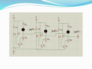
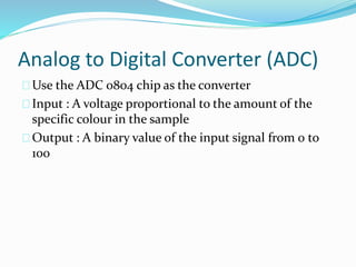
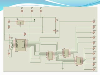
EN 2012 & EN 2022
Group project
Group 24
Group Members
T.D. Welagedara 120700P
P.I.L Wickramasuriya 120708X
M. W. A. D. S Wijesuriya 120727E
H. A. R. T Wijesekara 120715P
Contents
1. Introduction
2. Design
3. Components
Introduction
Project: RGB Colour Analyser
Objective: Measure and display the amount of red,
green and blue in a given colour sample
Only use basic analog and digital electronic
components (without programmable devices)
Design
Detector
ADC
Binary to BCD
converter
Display
Detector
Detects the amount of red, green or blue in the sample
Red, green and blue LEDs and LDRs
Points the LED at the sample and measure the amount
of reflected light using the LDR
Black cup to reduce the interference of outside light
Variable resistors to calibrate each sensor with respect
to a reference red, green, blue surface
Analog to Digital Converter (ADC)
Use the ADC 0804 chip as the converter
Input : A voltage proportional to the amount of the
specific colour in the sample
Output : A binary value of the input signal from 0 to
100
Binary to BCD Converter
Convert the 8-bit output of the ADC to three BCD
values
Need: To feed the display unit
Use three DM74185 chips connected as per the
following circuit diagram to achieve the task
Control Switches
Consists of 3 push buttons to activate each of the
green, red, blue sensors
While a push button is being pressed, the device will
display the percentile content of the corresponding
colour in the sample
Display
Displays the final output - the amount of specific
colour in the sample
Use three 7 segment displays
CMOS 4511 driver chips used as BCD decoders
Pull up resistors used for TTL to CMOS interfacing
Components
LEDs - Ultra Bright
LDRs
ADC0804 - No external clock required
DM74185
4511 decoders
7 segment display – common cathode
2N3904 transistor
Resistors, capacitors, diodes and other electronic
devices (7805 regulator, 555 timer)
Results obtained
Due to the interference from the outside light , there
were some variations in the calculations
Shows considerably accurate results in the testing.
Intended results were obtained.
Thank you!

RGB colour analyzer without a programmming device.

  • 1.
    EN 2012 &EN 2022 Group project Group 24
  • 2.
    Group Members T.D. Welagedara120700P P.I.L Wickramasuriya 120708X M. W. A. D. S Wijesuriya 120727E H. A. R. T Wijesekara 120715P
  • 3.
  • 4.
    Introduction Project: RGB ColourAnalyser Objective: Measure and display the amount of red, green and blue in a given colour sample Only use basic analog and digital electronic components (without programmable devices)
  • 5.
  • 6.
    Detector Detects the amountof red, green or blue in the sample Red, green and blue LEDs and LDRs Points the LED at the sample and measure the amount of reflected light using the LDR Black cup to reduce the interference of outside light Variable resistors to calibrate each sensor with respect to a reference red, green, blue surface
  • 9.
    Analog to DigitalConverter (ADC) Use the ADC 0804 chip as the converter Input : A voltage proportional to the amount of the specific colour in the sample Output : A binary value of the input signal from 0 to 100
  • 10.
    Binary to BCDConverter Convert the 8-bit output of the ADC to three BCD values Need: To feed the display unit Use three DM74185 chips connected as per the following circuit diagram to achieve the task
  • 11.
    Control Switches Consists of3 push buttons to activate each of the green, red, blue sensors While a push button is being pressed, the device will display the percentile content of the corresponding colour in the sample
  • 14.
    Display Displays the finaloutput - the amount of specific colour in the sample Use three 7 segment displays CMOS 4511 driver chips used as BCD decoders Pull up resistors used for TTL to CMOS interfacing
  • 17.
    Components LEDs - UltraBright LDRs ADC0804 - No external clock required DM74185 4511 decoders 7 segment display – common cathode 2N3904 transistor Resistors, capacitors, diodes and other electronic devices (7805 regulator, 555 timer)
  • 18.
    Results obtained Due tothe interference from the outside light , there were some variations in the calculations Shows considerably accurate results in the testing. Intended results were obtained.
  • 19.