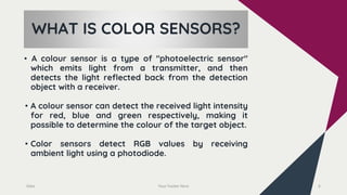
A color sensor detects the color of an object by measuring the intensity of light reflected in the red, green, and blue wavelengths. It works by emitting white light and using filters to measure the light reflected in the red, green, and blue wavelengths separately. Common applications include grading colored products, detecting markings, and controlling RGB LEDs. The color sensor can be easily interfaced with an Arduino board to read and interpret the RGB values.
2. INDEX
INDEX
➢ INTRODUCTION
➢ WHAT IS A SENSOR?
➢ WHAT IS A COLOR SENSOR?
➢ WORKING PRINCIPLE
➢ APPLICATIONS
➢ EXAMPLES
➢ INTERFACE WITH ARDUINO 2
3. INTRODUCTION
Date 3
We live in a World of Sensors. You can find different types of
Sensors in your homes, offices, cars etc. working to make our
lives easier by turning on the lights by detecting our
presence, adjusting the room temperature, detect smoke or
fire, make us delicious coffee, open garage doors as soon as
our car is near the door and many other tasks.
4. WHAT IS SENSORS?
A sensor is a device that produces an output signal for the
purpose of sensing a physical phenomenon. In the broadest
definition, a sensor is a device, module, machine, or
subsystem that detects events or changes in its
environment and sends the information to other electronics,
frequently a computer processor.
Date Your Footer Here 4
6. WHAT IS COLOR SENSORS?
• A colour sensor is a type of "photoelectric sensor"
which emits light from a transmitter, and then
detects the light reflected back from the detection
object with a receiver.
• A colour sensor can detect the received light intensity
for red, blue and green respectively, making it
possible to determine the colour of the target object.
• Color sensors detect RGB values by receiving
ambient light using a photodiode.
Date Your Footer Here 6
7. WORKING PRINCIPLE
7
● Colour sensors contain a white light emitter to illuminate the
surface. Three filters with wavelength sensitivities at 580nm,
540nm, 450nm to measure the wavelengths of red, green and
blue colors respectively.
● Based on the activation of these filters, the color of the material
is categorized. A light to voltage converter is also present in the
sensor. The sensor responds to color by generating a voltage
proportional to the detected color.
9. APPLICATIONS
● Colour sensors are applied to measure, detect the color of
the surfaces. These sensors have a wide range of
applications in industrial, medical and security systems.
● Some of the applications are the light color temperature
measurement, RGB LED consistency control, medical
diagnosis systems, health fitness systems, industrial process
control, etc
● Colour sensors are majorly used to grade coloured products,
distinguish coded markings detect the presence of adhesives
or data codes on a package.
● The technology has a wide range of applications in various
industries such as textile, automation, automotive, food,
printing, pharmaceutical, and many more.
9
10. 10
TCS3200
EXAMPLES
● In the TCS3200, the light-to-frequency
converter reads an 8 x 8 array of
photodiodes.
● 16 photodiodes have blue filters, 16
photodiodes have green filters, 16
photodiodes have red filters, and 16
photodiodes are clear with no filters.
12. ● The TCS3200 and TCS3210 programmable color light-to-
frequency converters that combine configurable silicon
photodiodes and a current-to-frequency converter on a
single monolithic CMOS integrated circuit.
● The output is a square wave (50% duty cycle) with
frequency directly proportional to light intensity
(irradiance).
● The full-scale output frequency can be scaled by one of
three preset values via two control input pins.
● Digital inputs and digital output allow direct interface to
a microcontroller or other logic circuitry.
● Output enable (OE) places the output in the high-
impedance state for multiple-unit sharing of a
microcontroller input line.
12
13. 13
AS73211
EXAMPLES
● The AS73211 is a low power,
low noise integrated color
sensor.
● Three channels convert light
signals via photodiodes to a
digital result and realize a
continuous or triggered
measurement.
15. 15
SEN-11195
EXAMPLES
● They can be complicated to interface
to since RGB data often has to be
derived using complex signal
processing.
● Secondly, they’re less than rugged,
and when you want to deploy one in
the field you need a device that can
stand up to the weather.
● Even moisture in the air can make an
unprotected sensor unreliable.
16. 16
● Atlas solved these problems by embedding the light
sensor in a rugged housing below a layer of
transparent epoxy which protects the sensor from
moisture while still allowing light to get in.
● The resulting light probe is water- and dust-proof,
sleet and ice tolerant, non reactive in salt water and
will readily sink when submerged.
17. • To communicate with the sensor we don't need anything other
than five GPIO pins of the Arduino, and that is why we have
used GPIO 8,7,6,5,4 pins of the Arduino.
• To power the sensor we have used the 5V and Ground pins of
the Arduino Board.
• The TCS3200 Color Sensor module has 8 pins; those are VCC,
OUT, S3, S2, S1, S0, 0E, and GND. All the pins of this sensor
module are digital, except VCC and Ground.
17
INTERFACE WITH ARDUINO
19. // Initialize the variables
int redValue = 0;
int greenValue = 0;
int blueValue = 0;
void setup() {
// Set the pins for the color sensor module
pinMode(S0, OUTPUT);
pinMode(S1, OUTPUT);
pinMode(S2, OUTPUT);
pinMode(S3, OUTPUT);
pinMode(OUT, INPUT);
// Set the frequency scaling to 20%
digitalWrite(S0, HIGH);
digitalWrite(S1, LOW);
// Print the headers for the serial output
Serial.begin(9600);
Serial.println("Color");
}
void loop() {
// Set the color sensor to detect red light
digitalWrite(S2, LOW);
digitalWrite(S3, LOW);
delay(10);
// Read the red value
redValue = pulseIn(OUT, LOW);
// Set the color sensor to detect green light
digitalWrite(S2, HIGH);
digitalWrite(S3, HIGH);
delay(10);
// Read the green value
greenValue = pulseIn(OUT, LOW);
// Set the color sensor to detect blue light
digitalWrite(S2, LOW);
digitalWrite(S3, HIGH);
delay(10);
// Read the blue value
blueValue = pulseIn(OUT, LOW);
// Determine the color based on the RGB values
if (redValue > greenValue && redValue >
blueValue) {
Serial.println("Red");
} else if (greenValue > redValue && greenValue
> blueValue) {
Serial.println("Green");
} else if (blueValue > redValue && blueValue >
greenValue) {
Serial.println("Blue");
} else if (redValue > 200 && greenValue > 200
&& blueValue > 200) {
Serial.println("White");
} else if (redValue < 50 && greenValue < 50 &&
blueValue < 50) {
Serial.println("Black");
} else {
Serial.println("Unknown");
}
// Wait for a short period before taking the next
measurement
delay(1000);
}
// Define the pins for the color sensor module
#define S0 2
#define S1 3
#define S2 4
#define S3 5
#define OUT 6
20. REFERENCE
• TCS3200, TCS3210 PROGRAMMABLE COLOR LIGHT-TO-
FREQUENCY CONVERTER Texas Advanced Optoelectronic
Solutions Inc.
• https://www.mouser.com/datasheet/2/588/AS73211_DS0005
56_3-01-1366202.pdf
• https://cdn-shop.adafruit.com/datasheets/TCS34725.pdf
• https://core-electronics.com.au/color-detector-sensor.html
• https://www.keyence.co.in/ss/products/sensor/sensorbasics
/color/info/
20
A sensor is a device that detects and responds to some type of input from the physical environment. The input can be light, heat, motion, moisture, pressure or any number of other environmental phenomena. The output is generally a signal that is converted to a human-readable display at the sensor location or transmitted electronically over a network for reading or further processing.Sensors play a imp role in the internet of things. photoelectric sensor
The TCS3200 and TCS3210 programmable color light-to-frequency converters that combine configurable silicon photodiodes and a current-to-frequency converter on a single monolithic CMOS integrated circuit. The output is a square wave (50% duty cycle) with frequency directly proportional to light intensity (irradiance). The full-scale output frequency can be scaled by one of three preset values via two control input pins. Digital inputs and digital output allow direct interface to a microcontroller or other logic circuitry. Output enable (OE) places the output in the high-impedance state for multiple-unit sharing of a microcontroller input line.