Download as ODP, PPTX
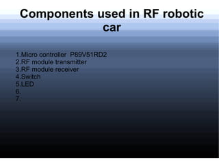
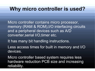


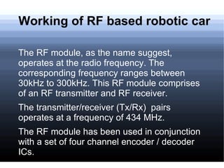


This document discusses the components used in an RF robotic car, including a microcontroller, RF transmitter and receiver modules, switches, LEDs, and a power supply. It describes how the microcontroller is used and its advantages. It then explains how the RF transmitter encodes switch signals and sends them to the receiver and decoder. Finally, it provides a flowchart and code for controlling the robotic car motors based on switch inputs.