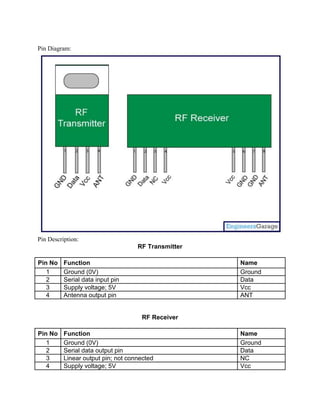
As explained earlier (refer RFID interfacing with 8051 & with AVR), an RFID module

consists of an RFID Reader, a line converter (usually MAX232) and a COM port. The

line converter of this module converts the TTL logic voltage of RFID Reader to RS232

logic. Therefore, to convert the voltage level from such an RFID module, another

MAX232 is used to interface it with a microcontroller.


One can also use an RFID Reader directly to interface with the controller, thus avoiding

the need of voltage level converters. Here both the MAX232s have been eliminated

from the circuit and RFID reader is directly connected with the PIC microcontroller.


The following table explains the pin diagram of the RFID Reader module.


Pin No.         Name                   Description
1               Vcc                    Supply Voltage; 5V
2               GND                    Ground (0V)
3               BEEP                   Beep or LED drive
4               ANT                    No Use
5               ANT                    No Use
6                SEL                    High is RS232, Low is Weigand
7                RS232                  TTL output data
8                D1                     Weigand Data 1
9                D0                     Weigand Data 0


Another part of the RFID system is RFID tag, which contains 12 bytes of unique data.

As the tag comes in the range of the Reader Module, it gets activated and transmits this

unique code. (For more detail on working of RFID system, refer the article on RFID) The

objective here is to receive this 12 byte unique code and display on a 16x2 LCD using

PIC18F4550.


With the RFID interfacing, this article also explains the USART interrupt which is an

internal interrupt. (For external interrupts, refer PIC Hardware interrupts) The internal

interrupts, unlike hardware interrupts, are associated with internal peripherals of the

controller. To use the USART interrupt, following registers have to be configured

accordingly.


1. INTCON (Interrupt Control Register)

Bit 7    Bit 6     Bit 5              Bit 4      Bit 3       Bit 2       Bit 1    Bit 0
GIE/GIEH PEIE/GIEL TMR0IE             INT0IE     RBIE        TMR0IF      INT0IF   RBIF


PEIE/GIEL: This bit is used to enable/disable all the peripheral interrupts (Internal

interrupts) of the controller. But GIE/GIEH bit must be set to high first.

       1 = Enables all Peripheral Interrupts

       0 = Disables all Peripheral Interrupts
GIE/GIEH: This is Global Interrupt Enable bit. This bit is set to high to enable all

interrupts of the PIC18F4550.

        1 = Enables interrupts

        0 = Disables all interrupts


2. PIR1 (Peripheral Interrupt Request 1)

Bit 7       Bit 6       Bit 5         Bit 4   Bit 3      Bit 2       Bit 1      Bit 0
SPPIF       ADIF        RCIF          TXIF    SSPIF      CCP1IF      TMR2IF     TMR1IF


TXIF: This is Transmission interrupt flag which is set to high when TXREG* is empty.

RCIF: This is Reception interrupt flag which is set to low when reception is complete.

*TXREG : EUSART Transmit Register (The data to be transmitted is stored in this

register)


3. PIE1 (Peripheral Interrupt Enable 1)

Bit 7       Bit 6       Bit 5         Bit 4   Bit 3      Bit 2       Bit 1      Bit 0
SPPIE       ADIE        RCIE          TXIE    SSPIE      CCP1IE      TMR2IE     TMR1IE


TXIE: This bit is used to enable/disable the Transmission (Tx) interrupt.

RCIE: This bit is used to enable/disable the Reception (Rx) interrupt.

Refer PIC EUSART registers for more details.


The connections of RFID reader module and LCD with the microcontroller are shown in

the circuit diagram tab.
Programming Steps:

1. Set the baud rate of PIC’s USART of to 9600 bps.

2. Set the SPEN and CREN bits to ‘1’ (RCSTA Register).

3. Set the GIE and PEIE to ‘1’ (INTCON Register).

4. Store the 12 byte data into an array when Reception Interrupt is generated.

5. Print the all stored data on the LCD. Refer displaying text on LCD using PIC.


Image:


Learn Analog System Design with Texas Instruments!
The RF module, as the name suggests, operates at Radio Frequency. The

corresponding frequency range varies between 30 kHz & 300 GHz. In this RF system,

the digital data is represented as variations in the amplitude of carrier wave. This kind of

modulation is known as Amplitude Shift Keying (ASK).


Transmission through RF is better than IR (infrared) because of many reasons. Firstly,

signals through RF can travel through larger distances making it suitable for long range

applications. Also, while IR mostly operates in line-of-sight mode, RF signals can travel

even when there is an obstruction between transmitter & receiver. Next, RF

transmission is more strong and reliable than IR transmission. RF communication uses

a specific frequency unlike IR signals which are affected by other IR emitting sources.


This RF module comprises of an RF Transmitter and an RF Receiver. The

transmitter/receiver (Tx/Rx) pair operates at a frequency of 434 MHz. An RF transmitter

receives serial data and transmits it wirelessly through RF through its antenna

connected at pin4. The transmission occurs at the rate of 1Kbps - 10Kbps.The

transmitted data is received by an RF receiver operating at the same frequency as that

of the transmitter.


The RF module is often used alongwith a pair of encoder/decoder. The encoder is used

for encoding parallel data for transmission feed while reception is decoded by a

decoder.    HT12E-HT12D,       HT640-HT648,       etc.   are    some     commonly     used

encoder/decoder pair ICs.
Pin Diagram:


Pin Description:
                                    RF Transmitter

Pin No    Function                                   Name
   1      Ground (0V)                                Ground
   2      Serial data input pin                      Data
   3      Supply voltage; 5V                         Vcc
   4      Antenna output pin                         ANT


                                     RF Receiver

Pin No    Function                                   Name
   1      Ground (0V)                                Ground
   2      Serial data output pin                     Data
   3      Linear output pin; not connected           NC
   4      Supply voltage; 5V                         Vcc
5   Supply voltage; 5V   Vcc
6   Ground (0V)          Ground
7   Ground (0V)          Ground
8   Antenna input pin    ANT

Rf module

  • 1.
    As explained earlier(refer RFID interfacing with 8051 & with AVR), an RFID module consists of an RFID Reader, a line converter (usually MAX232) and a COM port. The line converter of this module converts the TTL logic voltage of RFID Reader to RS232 logic. Therefore, to convert the voltage level from such an RFID module, another MAX232 is used to interface it with a microcontroller. One can also use an RFID Reader directly to interface with the controller, thus avoiding the need of voltage level converters. Here both the MAX232s have been eliminated from the circuit and RFID reader is directly connected with the PIC microcontroller. The following table explains the pin diagram of the RFID Reader module. Pin No. Name Description 1 Vcc Supply Voltage; 5V 2 GND Ground (0V) 3 BEEP Beep or LED drive 4 ANT No Use 5 ANT No Use
  • 2.
    6 SEL High is RS232, Low is Weigand 7 RS232 TTL output data 8 D1 Weigand Data 1 9 D0 Weigand Data 0 Another part of the RFID system is RFID tag, which contains 12 bytes of unique data. As the tag comes in the range of the Reader Module, it gets activated and transmits this unique code. (For more detail on working of RFID system, refer the article on RFID) The objective here is to receive this 12 byte unique code and display on a 16x2 LCD using PIC18F4550. With the RFID interfacing, this article also explains the USART interrupt which is an internal interrupt. (For external interrupts, refer PIC Hardware interrupts) The internal interrupts, unlike hardware interrupts, are associated with internal peripherals of the controller. To use the USART interrupt, following registers have to be configured accordingly. 1. INTCON (Interrupt Control Register) Bit 7 Bit 6 Bit 5 Bit 4 Bit 3 Bit 2 Bit 1 Bit 0 GIE/GIEH PEIE/GIEL TMR0IE INT0IE RBIE TMR0IF INT0IF RBIF PEIE/GIEL: This bit is used to enable/disable all the peripheral interrupts (Internal interrupts) of the controller. But GIE/GIEH bit must be set to high first. 1 = Enables all Peripheral Interrupts 0 = Disables all Peripheral Interrupts
  • 3.
    GIE/GIEH: This isGlobal Interrupt Enable bit. This bit is set to high to enable all interrupts of the PIC18F4550. 1 = Enables interrupts 0 = Disables all interrupts 2. PIR1 (Peripheral Interrupt Request 1) Bit 7 Bit 6 Bit 5 Bit 4 Bit 3 Bit 2 Bit 1 Bit 0 SPPIF ADIF RCIF TXIF SSPIF CCP1IF TMR2IF TMR1IF TXIF: This is Transmission interrupt flag which is set to high when TXREG* is empty. RCIF: This is Reception interrupt flag which is set to low when reception is complete. *TXREG : EUSART Transmit Register (The data to be transmitted is stored in this register) 3. PIE1 (Peripheral Interrupt Enable 1) Bit 7 Bit 6 Bit 5 Bit 4 Bit 3 Bit 2 Bit 1 Bit 0 SPPIE ADIE RCIE TXIE SSPIE CCP1IE TMR2IE TMR1IE TXIE: This bit is used to enable/disable the Transmission (Tx) interrupt. RCIE: This bit is used to enable/disable the Reception (Rx) interrupt. Refer PIC EUSART registers for more details. The connections of RFID reader module and LCD with the microcontroller are shown in the circuit diagram tab.
  • 4.
    Programming Steps: 1. Setthe baud rate of PIC’s USART of to 9600 bps. 2. Set the SPEN and CREN bits to ‘1’ (RCSTA Register). 3. Set the GIE and PEIE to ‘1’ (INTCON Register). 4. Store the 12 byte data into an array when Reception Interrupt is generated. 5. Print the all stored data on the LCD. Refer displaying text on LCD using PIC. Image: Learn Analog System Design with Texas Instruments!
  • 5.
    The RF module,as the name suggests, operates at Radio Frequency. The corresponding frequency range varies between 30 kHz & 300 GHz. In this RF system, the digital data is represented as variations in the amplitude of carrier wave. This kind of modulation is known as Amplitude Shift Keying (ASK). Transmission through RF is better than IR (infrared) because of many reasons. Firstly, signals through RF can travel through larger distances making it suitable for long range applications. Also, while IR mostly operates in line-of-sight mode, RF signals can travel even when there is an obstruction between transmitter & receiver. Next, RF transmission is more strong and reliable than IR transmission. RF communication uses a specific frequency unlike IR signals which are affected by other IR emitting sources. This RF module comprises of an RF Transmitter and an RF Receiver. The transmitter/receiver (Tx/Rx) pair operates at a frequency of 434 MHz. An RF transmitter receives serial data and transmits it wirelessly through RF through its antenna connected at pin4. The transmission occurs at the rate of 1Kbps - 10Kbps.The transmitted data is received by an RF receiver operating at the same frequency as that of the transmitter. The RF module is often used alongwith a pair of encoder/decoder. The encoder is used for encoding parallel data for transmission feed while reception is decoded by a decoder. HT12E-HT12D, HT640-HT648, etc. are some commonly used encoder/decoder pair ICs.
  • 6.
    Pin Diagram: Pin Description: RF Transmitter Pin No Function Name 1 Ground (0V) Ground 2 Serial data input pin Data 3 Supply voltage; 5V Vcc 4 Antenna output pin ANT RF Receiver Pin No Function Name 1 Ground (0V) Ground 2 Serial data output pin Data 3 Linear output pin; not connected NC 4 Supply voltage; 5V Vcc
  • 7.
    5 Supply voltage; 5V Vcc 6 Ground (0V) Ground 7 Ground (0V) Ground 8 Antenna input pin ANT