Downloaded 243 times


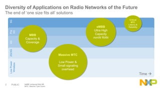
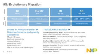
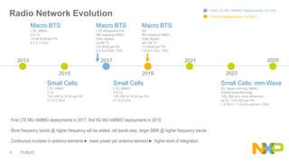
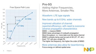


The document presents key insights from Paul Hart's presentation at the 5G Technology Summit, highlighting NXP Semiconductors' role in advancing RF power amplifier solutions for 5G technology. It discusses the evolution from 4G to 5G, emphasizing diverse applications, higher performance, and the necessity for improved spectrum management and network architecture. The roadmap outlines NXP's strategies for addressing challenges and enhancing performance through advanced technologies and collaborations in 5G integration.


![RF Module Design - [Chapter 6] Power Amplifier](https://cdn.slidesharecdn.com/ss_thumbnails/rfch6-150613070347-lva1-app6891-thumbnail.jpg?width=640&height=640&fit=bounds)


