Download as PDF, PPTX

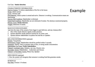
![Use Case Overview Diagram
Dr. Birgit Penzenstadler 5
[uml-diagrams.org 2010]](https://image.slidesharecdn.com/2017springcecs-54211-usagemodel-170720091848/85/Requirements-Engineering-Usage-models-5-320.jpg)
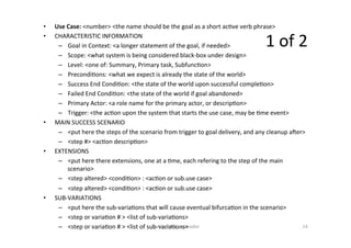
![Another
Use Case
Overview
Diagram
Dr. Birgit Penzenstadler 6
[Scoa W. Ambler 2007]](https://image.slidesharecdn.com/2017springcecs-54211-usagemodel-170720091848/85/Requirements-Engineering-Usage-models-6-320.jpg)
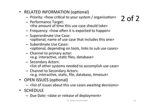
![Exercise: ATM
• Use case overview
• Use case template
• Scenario
Dr. Birgit Penzenstadler 8
[Scoa W. Ambler 2007]](https://image.slidesharecdn.com/2017springcecs-54211-usagemodel-170720091848/85/Requirements-Engineering-Usage-models-8-320.jpg)
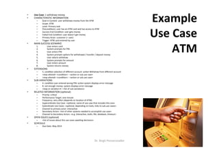
![Exercise: ATM
• Use case overview
• Use case template
• Scenario
Dr. Birgit Penzenstadler 13
[Scoa W. Ambler 2007]](https://image.slidesharecdn.com/2017springcecs-54211-usagemodel-170720091848/85/Requirements-Engineering-Usage-models-13-320.jpg)


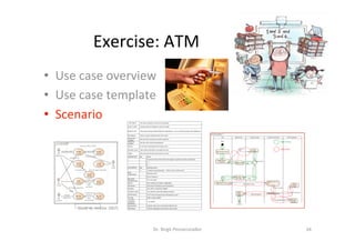
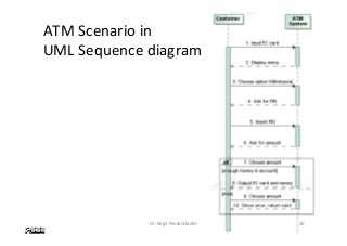
![Exercise: ATM
• Use case overview
• Use case template
• Scenario
Dr. Birgit Penzenstadler 35
[Scoa W. Ambler 2007]](https://image.slidesharecdn.com/2017springcecs-54211-usagemodel-170720091848/85/Requirements-Engineering-Usage-models-35-320.jpg)

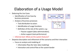
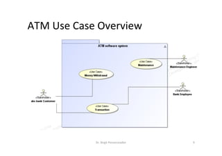
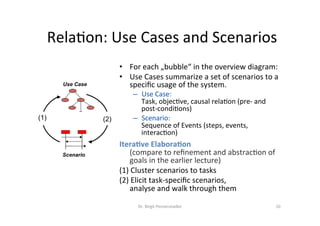
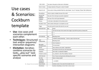
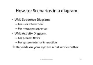
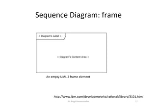
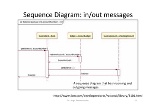
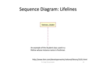
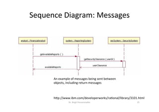
The document focuses on usage models in requirements engineering, particularly highlighting definitions and distinctions among usage models, use cases, and scenarios. It emphasizes the importance of understanding user interactions and system behavior, along with detailed methodologies for modeling through diagrams such as UML. Practical examples like an ATM system illustrate the structure of use cases and how to derive scenarios from them.


