Downloaded 328 times
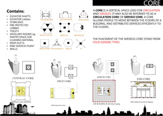
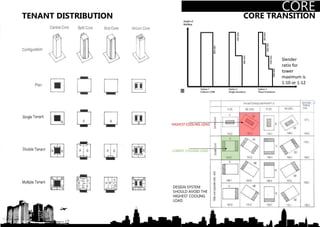
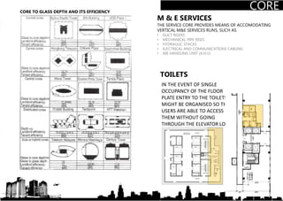
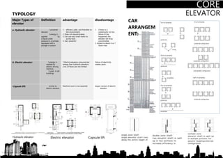
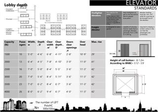
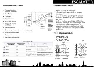
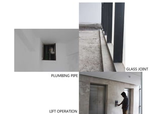
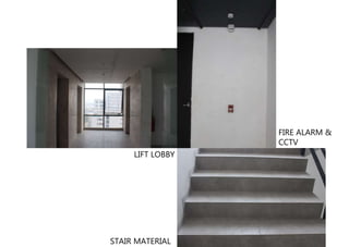
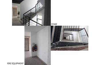
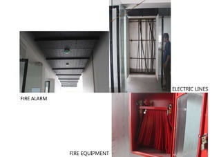
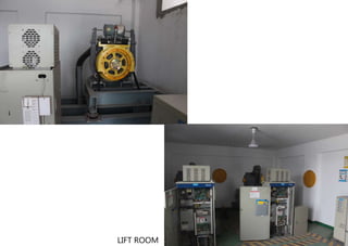
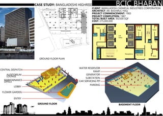
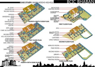
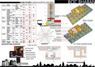
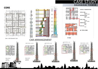


This document provides information about the core of a high-rise building. It defines a core as a vertical space used for circulation and services like elevators, staircases, and mechanical systems. Cores allow efficient distribution of these services to floors. The document discusses different core types and considerations for placement of mechanical and plumbing systems, as well as toilet access. Elevator types, sizes, and fire safety standards are also outlined.