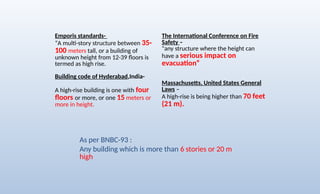
Emporis standards-
“A multi-storystructure between 35-
100 meters tall, or a building of
unknown height from 12-39 floors is
termed as high rise.
Building code of Hyderabad,India-
A high-rise building is one with four
floors or more, or one 15 meters or
more in height.
The International Conference on Fire
Safety –
"any structure where the height can
have a serious impact on
evacuation“
Massachusetts, United States General
Laws –
A high-rise is being higher than 70 feet
(21 m).
As per BNBC-93 :
Any building which is more than 6 stories or 20 m
high
4.
• Scarcity ofland in urban areas
• Increasing demand for business and residential space
• Economic growth
• Technological advancements
• Innovation in structural System
• Desire for Aesthetics in urban settings
• Concept of city skyline
• Cultural significance and prestige
• Human aspiration to build higher
Why High-Rise
5.
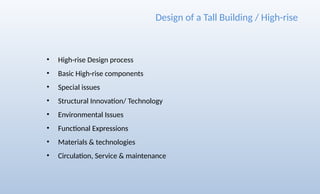
• High-rise Designprocess
• Basic High-rise components
• Special issues
• Structural Innovation/ Technology
• Environmental Issues
• Functional Expressions
• Materials & technologies
• Circulation, Service & maintenance
Design of a Tall Building / High-rise
6.
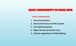
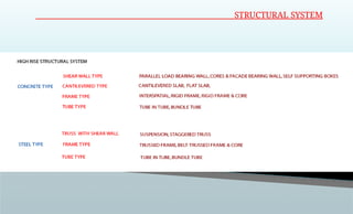
1. Structural System
2.Electromechanical & HVAC System
3. Fire Fighting System
4. Major Services & service Core
5. Rules & regulations of Tall buildings
Study Components:
Basic components of high-rise
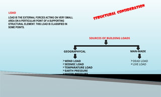
LOAD IS THEEXTERNAL FORCES ACTING ON VERY SMALL
AREA ON A PERTICULAR POINT OF A SUPPORTING
STRUCTURAL ELEMENT. THIS LOAD IS CLASSIFIED IN
SOME POINTS.
LOAD
SOURCES OF BUILDING LOADS
GEOGRAPHYCAL MAN-MADE
WIND LOAD
SEISMIC LOAD
TEMPARATURE LOAD
EARTH PRESSURE
WATER PRESSURE
DEAD LOAD
LIVE LOAD
STRUCTURAL CONSIDERATION
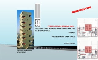
SHEAR WALL TYPE
CORES& FACADE BEARING WALL
VERTICAL LOAD BEARING WALL & CORE ARE THE
MAIN STRUCTURAL
ELEMET
PROVIDE MORE OPEN SPACE
EXPRESSION
Solid void relationship are exposed
Fig:KANCHANJUNGA
APARTMENT
11.
CANTILEVERED TYPE
CONCRETE
TYPE
CANTILEVERED SLAB
CENTRELCORE ACT MAIN STRUCTURAL
ELEMENT & SUPPORTED THE FLOOR SLAB
PROVIDE COLUMN FREE SPACE
LARGE QUANTITIES OF STEEL ARE REQUIRED
FOR LARGE SLAB PROJECTION
EXPRESSION
Horizontal lines are boldly
exposed
And core is always placed in centre position
price tower
Johnson wax building,
USA
Banco de bilbao Spain
FLAT SLAB
THICK CONCRETE FLOOR SLAB SUPPORT ON COLUMN
THERE IS NO DROP PANEL & CAPITAL ON THE TOP OF THE COLUMN
HAS NO DEEP BEAMS ALLOWING FOR A MINIMUM STORY HEIGHT
12.
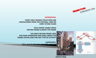
FRAME TYPE
CONCRETE TYPE
INTERSPATIAL
STORYHIGH FRAMED STRUCTURES ARE
CANTILEVERED FROM THE CENTERAL CORE ON
EVERY OTHER FLOOR
THUS CREATE USABLE SPACE
WITHIN FRAME & ABOVE THE FRAME
THE SPACE WITHIN FRAME USED
FOR FIXED OPERATION AND SPACE ABOVE THE
FRAME CAN BE USED FOR ANY TYPE OF ACTIVITY
EXPRESSION
Inter spatial elements are boldly exposed
Fig:State Trading
13.
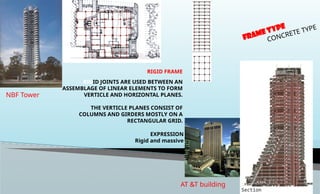
RIGID FRAME
EXPRESSION
Rigid andmassive
FRAME TYPE
CONCRETE TYPE
AT &T building
RIGID JOINTS ARE USED BETWEEN AN
ASSEMBLAGE OF LINEAR ELEMENTS TO FORM
VERTICLE AND HORIZONTAL PLANES.
THE VERTICLE PLANES CONSIST OF
COLUMNS AND GIRDERS MOSTLY ON A
RECTANGULAR GRID.
NBF Tower
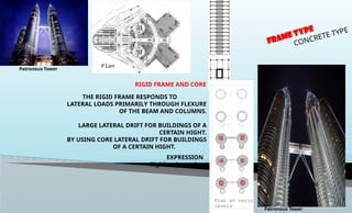
14.
RIGID FRAME ANDCORE
THE RIGID FRAME RESPONDS TO
LATERAL LOADS PRIMARILY THROUGH FLEXURE
OF THE BEAM AND COLUMNS.
LARGE LATERAL DRIFT FOR BUILDINGS OF A
CERTAIN HIGHT.
BY USING CORE LATERAL DRIFT FOR BUILDINGS
OF A CERTAIN HIGHT.
EXPRESSION
Rigid and massive
FRAME TYPE
CONCRETE TYPE
Patronous Tower
Patronous Tower
15.
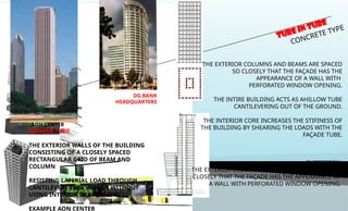
TUBE IN TUBE
CONCRETETYPE
Frankfurt Trade Fair Tower
AON CENTER
CHICAGO
EXPRESSION
THE EXTERIOR COLUMNS AND BEAMS ARE SPACED SO
CLOSELY THAT THE FAÇADE HAS THE APPEARANCE OF
A WALL WITH PERFORATED WINDOW OPENING.
THE EXTERIOR COLUMNS AND BEAMS ARE SPACED
SO CLOSELY THAT THE FAÇADE HAS THE
APPEARANCE OF A WALL WITH
PERFORATED WINDOW OPENING.
THE INTIRE BUILDING ACTS AS AHILLOW TUBE
CANTILEVERING OUT OF THE GROUND.
THE INTERIOR CORE INCREASES THE STIFINESS OF
THE BUILDING BY SHEARING THE LOADS WITH THE
FAÇADE TUBE.
DG BANK
HEADQUARTERS
FRAMED TUBE
THE EXTERIOR WALLS OF THE BUILDING
CONSISTING OF A CLOSELY SPACED
RECTANGULAR GRID OF BEAM AND
COLUMN
RESISTING LATERIAL LOAD THROUGH
CANTILEVERE TUBE ACTION WITHOUT
USING INTERIOR BRACING
EXAMPLE AON CENTER
16.
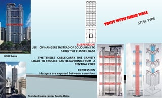
TRUSS WITH SHEARWALL
STEEL TYPE
USE OF HANGERS INSTEAD OF COLOUMNS TO
CARRY THE FLOOR LOADS
THE TENSILE CABLE CARRY THE GRAVITY
LOADS TO TRUSSES CANTILEAVERING FROM A
CENTRAL CORE
EXPRESSION
Hangers are exposed between a number
of floors
SUSPENSION
HSBC bank
Standard bank center South Africa
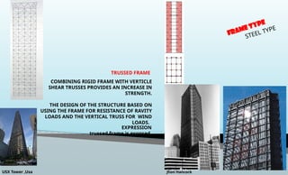
17.
FRAME TYPE
STEEL TYPE
TRUSSEDFRAME
EXPRESSION
trussed frame is exposed.
COMBINING RIGID FRAME WITH VERTICLE
SHEAR TRUSSES PROVIDES AN INCREASE IN
STRENGTH.
THE DESIGN OF THE STRUCTURE BASED ON
USING THE FRAME FOR RESISTANCE OF RAVITY
LOADS AND THE VERTICAL TRUSS FOR WIND
LOADS.
USX Tower ,Usa Jhon Hancock
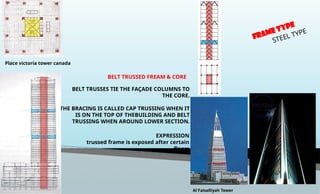
18.
BELT TRUSSED FREAM& CORE
BELT TRUSSES TIE THE FAÇADE COLUMNS TO
THE CORE.
THE BRACING IS CALLED CAP TRUSSING WHEN IT
IS ON THE TOP OF THEBUILDING AND BELT
TRUSSING WHEN AROUND LOWER SECTION.
EXPRESSION
trussed frame is exposed after certain
floors
FRAME TYPE
STEEL TYPE
Place victoria tower canada
Al Faisalliyah Tower
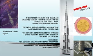
19.
STEEL TYPE
THE EXTERIORCOLUMNS AND BEAMS ARE
SPACED SO CLOSELY THAT THE FAÇADE HAS THE
APPEARANCE OF A WALL WITH
PERFORATED WINDOW OPENING.
THE INTIRE BUILDING ACTS AS AHILLOW TUBE
CANTILEVERING OUT OF THE GROUND.
THE INTERIOR CORE INCREASES THE STIFINESS
OF THE BUILDING BY SHEARING THE LOADS
WITH THE FAÇADE TUBE.
EXPRESSION
THE EXTERIOR COLUMNS AND BEAMS ARE SPACED
SO CLOSELY THAT THE FAÇADE HAS THE
APPEARANCE OF A WALL WITH PERFORATED
WINDOW OPENING.
TUBE IN TUBE
Millennium tower
Japan
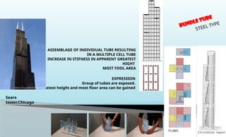
20.
BUNDLE TUBE
STEEL TYPE
EXPRESSION
Groupof tubes are exposed.
Greatest height and most floor area can be gained
ASSEMBLAGE OF INDIVIDUAL TUBE RESULTING
IN A MULTIPLE CELL TUBE
INCREASE IN STIFNESS IN APPARENT GREATEST
HIGHT
MOST FOOL AREA
Sears
tower,Chicago
21.
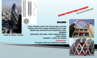
DIAGRID
STEEL FRAMED TUBETYPE STRUCTURAL SYSTEM
TRINGULAR STEEL FRAME GENERATES THE TUBE
BEAMS ARE SUPPORTED BY DIAGONAL STEEL
MEMBER
REQUARES LESS STEEL THEN CONVENTIONAL
STEEL FRAME
EXAMPLE SWISS- RE TOWER
EXPRESSION
Triangular grids are exposed in façade
OTHER Structural Element
Structural Element
Swiss re tower, London
22.
OTHER Structural Element
StructuralElement
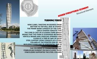
TURNING TORSO
NINE CUBES, TWISTING 90 DEGREES FROM
BOTTOM TO TOP WILL RISE 45 STORIES
THE FRAME WORK CONSISTS OF THE CORE,
CIRCLE SHAPED CONCETE TYPE
THE CORE IS CAST IN A SLIDING FORM WHICH
MEANS THAT THE FORM IS SUSPENDED BETWEEN
VERTICLE BEAMS AND CANSLIDE UPWARDS ONE
FLOOR AT A TIME BY WAY OF JACKS
STEEL SUPPORT SPINE CONSISTS OF A STEEL
COLUMN AT THE POINTED END OF THE
BUILDING FLOOR AND 20 HORIZANTAL AND 18
DIAGONAL STEEL ‘CIGAR’
THE COLUMNN IS CONNECTED TO TWO
STABILIZLNG ELEMENT ON EACH FLOOR. THESE
STAB ILIZERS SUPPORTED THE STEEL COLUMN
23.
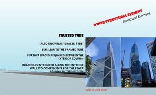
TRUSSED TUBE
ALSO KNOWNAS “BRACED TUBE”
SEMILIAR TO THE FRAMED TUBE
FURTHER SPACED REQUARED BETWEEN THE
EXTERIOR COLUMN
BRACING IS INTROUCED ALONG THE ENTERIOR
WALLS TO COMPENSTATE FOR THE FEWER
COLUMN BY TIEING THEM
OTHER Structural Element
Structural Element
Bank of china tower
24.
OTHER Structural Element
StructuralElement
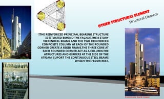
Commerz bank tower
ITHE REINFORCED PRINCIPAL BEARING STRUCTURE
IS SITUATED BEHIND THE FAÇADE.THE 8 STORY
VIERENDEEL BEAMS AND THE TWO REINFORCED
COMPOSITE COLUMN AT EACH OF THE ROUNDED
CORNER CREATE A RIGID FRAME.THE THREE CORE AT
EACH ROUNDED CORNER ACT AS A COLUMN.THE
ATRUCTURES AND GIRDERS AT THE SIDE OF THE
ATRIAM SUPORT THE CONTINUOUS STEEL BEAMS
WHICH THE FLOOR REST.
25.
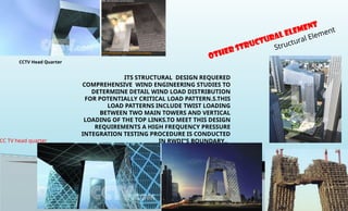
ITS STRUCTURAL DESIGNREQUERED
COMPREHENSIVE WIND ENGINEERING STUDIES TO
DETERMIINE DETAIL WIND LOAD DISTRIBUTION
FOR POTENTIALLY CRITICAL LOAD PATTERN.S.THIS
LOAD PATTERNS INCLUDE TWIST LOADING
BETWEEN TWO MAIN TOWERS AND VERTICAL
LOADING OF THE TOP LINKS.TO MEET THIS DESIGN
REQUIREMENTS A HIGH FREQUENCY PRESSURE
INTEGRATION TESTING PROCEDURE IS CONDUCTED
IN RWDI”S BOUNDARY..
OTHER Structural Element
Structural Element
CC TV head quarter
CCTV Head Quarter
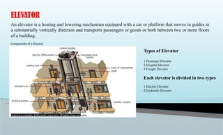
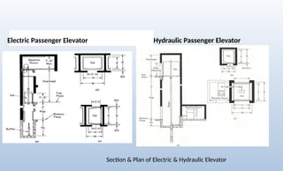
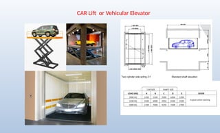
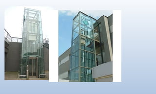
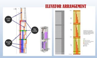
ELEVATOR
An elevator isa hosting and lowering mechanism equipped with a car or platform that moves in guides in
a substantially vertically direction and transports passengers or goods or both between two or more floors
of a building.
Components of a Elevator
Types of Elevator
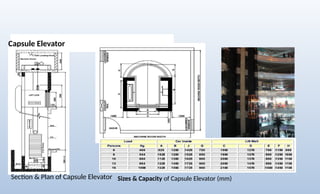
1.Passenger Elevator
2.Hospital Elevator
3.Freight Elevator
Each elevator is divided in two types
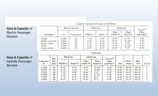
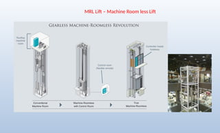
1.Electric Elevator
2.Hydraulic Elevator
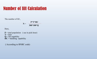
Number of liftCalculation
The number of lift ,
Here,
P = total population ( use in pick hour)
T = time
Q = lift capability
HC = handling capability
( According to BNBC code)
P*T*HC
300*100*Q
N =
39.
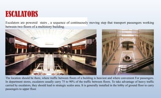
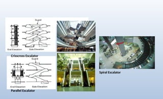
ESCALATORS
Escalators are poweredstairs , a sequence of continuously moving step that transport passengers working
between two floors of a multistory building.
The location should be there, where traffic between floors of a building is heaviest and where convenient For passengers.
In department stores, escalators usually carry 75 to 90% of the traffic between floors. To take advantage of heavy traffic
carried by escalators, they should lead to strategic scales area. It is generally installed in the lobby of ground floor to carry
passengers to upper floor.
40.
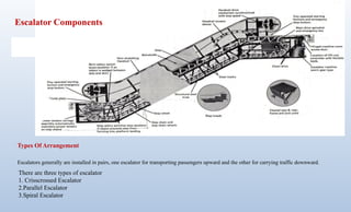
Escalator Components
Types OfArrangement
Escalators generally are installed in pairs, one escalator for transporting passengers upward and the other for carrying traffic downward.
There are three types of escalator
1. Crisscrossed Escalator
2.Parallel Escalator
3.Spiral Escalator
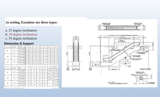
As setting, Escalatorare three types-
a. 25 degree inclination
b. 30 degree inclination
c. 35 degree inclination
Dimension & Support
43.
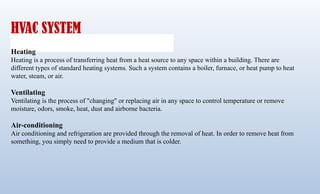
HVAC SYSTEM
Heating
Heating isa process of transferring heat from a heat source to any space within a building. There are
different types of standard heating systems. Such a system contains a boiler, furnace, or heat pump to heat
water, steam, or air.
Ventilating
Ventilating is the process of "changing" or replacing air in any space to control temperature or remove
moisture, odors, smoke, heat, dust and airborne bacteria.
Air-conditioning
Air conditioning and refrigeration are provided through the removal of heat. In order to remove heat from
something, you simply need to provide a medium that is colder.
HVAC IN SPACES
Mixingsystems
Mixing systems generally supply air in a manner that the air in the entire room is fully mixed. In cooling
mode, the cool supply air, typically around 55’F at design conditions, exits an outlet at high velocity, inducing
room air to provide mixing and temperature equalization. To enhance the mixing, diffusers are normally used
as the air outlets.
Displacement ventilation
Displacement systems introduce air at low velocities to cause minimal induction and mixing. This system is
primarily used for ventilation and space cooling applications. By doing so, the air quality in the occupied
zone is generally superior to that achieved with mixing room air distribution.
46.
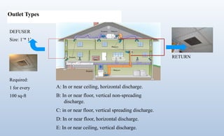
Outlet Types
RETURN
DEFUSER
Size: 1’*1’
Required:
1 for every
100 sq-ft
A: In or near ceiling, horizontal discharge.
B: In or near floor, vertical non-spreading
discharge.
C: in or near floor, vertical spreading discharge.
D: In or near floor, horizontal discharge.
E: In or near ceiling, vertical discharge.
47.
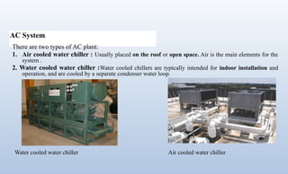
AC System
There aretwo types of AC plant:
1. Air cooled water chiller : Usually placed on the roof or open space. Air is the main elements for the
system .
2. Water cooled water chiller :Water cooled chillers are typically intended for indoor installation and
operation, and are cooled by a separate condenser water loop.
Water cooled water chiller Air cooled water chiller
48.
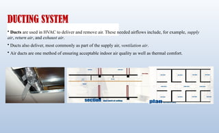
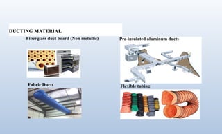
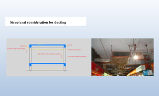
DUCTING SYSTEM
• Ductsare used in HVAC to deliver and remove air. These needed airflows include, for example, supply
air, return air, and exhaust air.
• Ducts also deliver, most commonly as part of the supply air, ventilation air.
• Air ducts are one method of ensuring acceptable indoor air quality as well as thermal comfort.
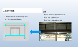
AIR CUTTER
A deviceused at the accessing door
of a air-conditioned space.
USE
. Protect from outer worm air flow
. Keep free from insects
. Keep free from outdoor dust
52.
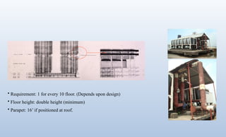
• Requirement: 1for every 10 floor. (Depends upon design)
• Floor height: double height (minimum)
• Parapet: 16’ if positioned at roof.
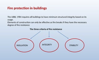
Fire protection inbuildings
The UBBL 1984 requires all buildings to have minimum structural integrity based on its
usage.
Elements of construction can only be effective as fire breaks if they have the necessary
degree of fire resistance
INSULATION STABILITY
INTEGRITY
The three criteria of fire resistance
55.
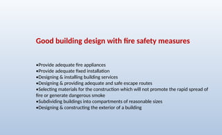
Good building designwith fire safety measures
•Provide adequate fire appliances
•Provide adequate fixed installation
•Designing & installing building services
•Designing & providing adequate and safe escape routes
•Selecting materials for the construction which will not promote the rapid spread of
fire or generate dangerous smoke
•Subdividing buildings into compartments of reasonable sizes
•Designing & constructing the exterior of a building
56.
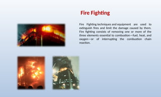
Fire Fighting
Fire Fightingtechniques and equipment are used to
extinguish fires and limit the damage caused by them.
Fire fighting consists of removing one or more of the
three elements essential to combustion—fuel, heat, and
oxygen—or of interrupting the combustion chain
reaction.
57.
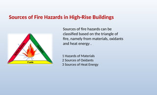
Sources of firehazards can be
classified based on the triangle of
fire, namely from materials, oxidants
and heat energy .
Sources of Fire Hazards in High-Rise Buildings
1 Hazards of Materials
2 Sources of Oxidants
3 Sources of Heat Energy
58.
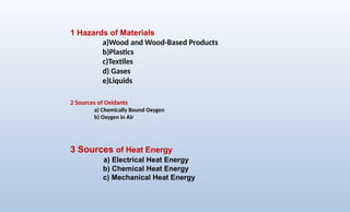
2 Sources ofOxidants
a) Chemically Bound Oxygen
b) Oxygen in Air
3 Sources of Heat Energy
a) Electrical Heat Energy
b) Chemical Heat Energy
c) Mechanical Heat Energy
1 Hazards of Materials
a)Wood and Wood-Based Products
b)Plastics
c)Textiles
d) Gases
e)Liquids
59.
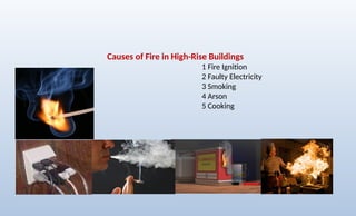
Causes of Firein High-Rise Buildings
1 Fire Ignition
2 Faulty Electricity
3 Smoking
4 Arson
5 Cooking
60.
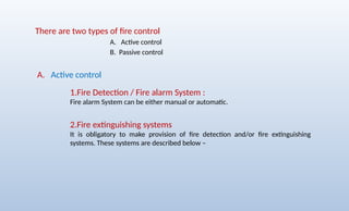
There are twotypes of fire control
A. Active control
B. Passive control
A. Active control
1.Fire Detection / Fire alarm System :
Fire alarm System can be either manual or automatic.
2.Fire extinguishing systems
It is obligatory to make provision of fire detection and/or fire extinguishing
systems. These systems are described below –
61.
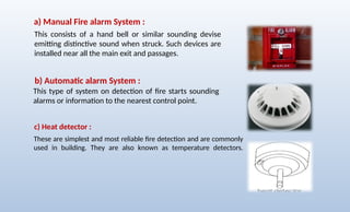
These are simplestand most reliable fire detection and are commonly
used in building. They are also known as temperature detectors.
This consists of a hand bell or similar sounding devise
emitting distinctive sound when struck. Such devices are
installed near all the main exit and passages.
This type of system on detection of fire starts sounding
alarms or information to the nearest control point.
a) Manual Fire alarm System :
b) Automatic alarm System :
c) Heat detector :
62.
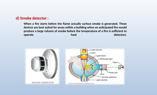
When a firestarts before the flame actually surface smoke is generated. These
devices are best suited for areas within a building when an anticipated fire would
produce a large column of smoke before the temperature of a fire is sufficient to
operate heat detectors.
d) Smoke detector :
63.
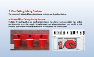
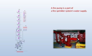
2. Fire ExtinguishingSystem :
The commonly adopted fire extinguishing systems are described below:
a) Manual Fire Extinguishing System :
Portable fire extinguisher can be of carbon dioxide type, large foam generation type and so
on. Depending upon the capacity, the discharge from a fire extinguisher may last 20 to 120
seconds. Sometimes buckets full of water and dry sand are also installed.
64.
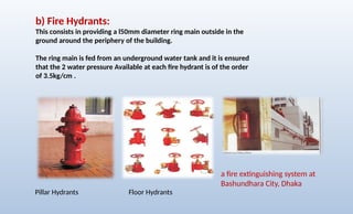
b) Fire Hydrants:
Thisconsists in providing a l50mm diameter ring main outside in the
ground around the periphery of the building.
The ring main is fed from an underground water tank and it is ensured
that the 2 water pressure Available at each fire hydrant is of the order
of 3.5kg/cm .
a fire extinguishing system at
Bashundhara City, Dhaka
Pillar Hydrants Floor Hydrants
65.
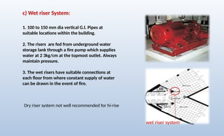
c) Wet riserSystem:
1. 100 to 150 mm dia vertical G.I. Pipes at
suitable locations within the building.
2. The risers are fed from underground water
storage lank through a fire pump which supplies
water at 2 3kg/cm at the topmost outlet. Always
maintain pressure.
3. The wet risers have suitable connections at
each floor from where constant supply of water
can be drawn in the event of fire.
wet riser system
Dry riser system not well recommended for hi-rise
66.
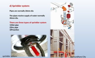
sprinkler system BashundharaCity
d) Sprinkler system:
Pipes are normally 20mm dia
The pipes receive supply of water normally
40mm dia.
There are three types of sprinkler system
1)Wet pipe
2)Dry pipe
3)Preaction
67.
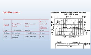
Hazard
Design Water
Density
* MinimumArea
(sq.m)
Minimum
duration of
water
availability
Light 2.25 mm/min. 84 sq.m 30 min.
Ordinary 5.0 mm/min. 144 to 216 sq.m 60 min.
High
7.5 to 30.0
mm/min.
260 to 300 sq.m 90 min.
Sprinkler system:
68.
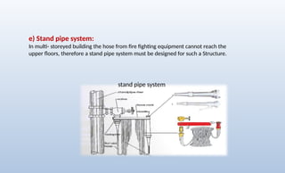
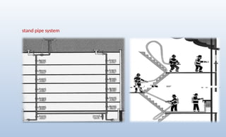
e) Stand pipesystem:
In multi- storeyed building the hose from fire fighting equipment cannot reach the
upper floors, therefore a stand pipe system must be designed for such a Structure.
stand pipe system
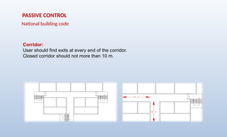
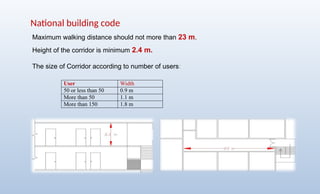
Height of thecorridor is minimum 2.4 m.
The size of Corridor according to number of users:
Maximum walking distance should not more than 23 m.
User Width
50 or less than 50 0.9 m
More than 50 1.1 m
More than 150 1.8 m
National building code
74.
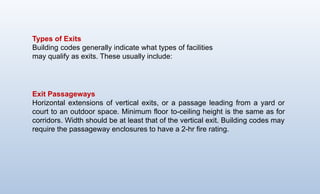
Types of Exits
Buildingcodes generally indicate what types of facilities
may qualify as exits. These usually include:
Exit Passageways
Horizontal extensions of vertical exits, or a passage leading from a yard or
court to an outdoor space. Minimum floor
to-ceiling height is the same as for
corridors. Width should be at least that of the vertical exit. Building codes may
require the passageway en
closures to have a 2-hr fire rating.
75.
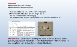
Exit Doors-
doors providingaccess to streets
doors to stairs and exit passageways
Interior Stairs—stairs within a building that serve as an exit. Building codes
generally re
quire such stairs to be constructed of noncom
bustible materials but
may except one-story or two-story, low-hazard buildings.
There should be one exit door for every 50 persons.
Minimum width of the door is 1 m & height is 2 m.
The exit door should be side swinging.
The door should be of outer direction if the user number is more than 50.
76.
Stair should bemade of
fire proofing material
Landing should not less than
the width of the stair.
Stair: Minimum width
of stair is 1.5 m.
Hand rail should be placed
both side of the stair.
There should be a
additional hand rail at the
middle if the width of the
stair is more than 2.2 m.
77.
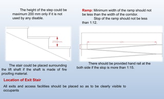
The height ofthe step could be
maximum 200 mm only if it is not
used by any disable.
The stair could be placed surrounding
the lift shaft if the shaft is made of fire
proofing material.
Ramp: Minimum width of the ramp should not
be less than the width of the corridor.
Slop of the ramp should not be less
than 1:12.
There should be provided hand rail at the
both side if the slop is more than 1:15.
All exits and access facilities should be placed so as to be clearly visible to
occupants
Location of Exit Stair
78.
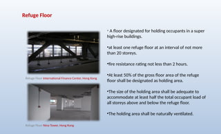
Refuge Floor
• Afloor designated for holding occupants in a super
high-rise buildings.
•at least one refuge floor at an interval of not more
than 20 storeys.
•fire resistance rating not less than 2 hours.
•At least 50% of the gross floor area of the refuge
floor shall be designated as holding area.
•The size of the holding area shall be adequate to
accommodate at least half the total occupant load of
all storeys above and below the refuge floor.
•The holding area shall be naturally ventilated.
Refuge Floor International Finance Center, Hong Kong
Refuge Floor Nina Tower, Hong Kong
79.
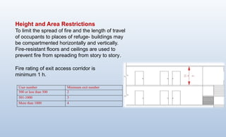
Height and AreaRestrictions
To limit the spread of fire and the length of travel
of occupants to places of refuge- build
ings may
be compartmented horizontally and vertically.
Fire-resistant floors and ceilings are used to
prevent fire from spreading from story to story.
User number Minimum exit number
500 or less than 500 2
501-1000 3
More than 1000 4
Fire rating of exit access corridor is
minimum 1 h.
80.
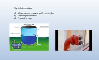
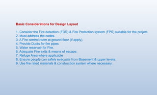
Basic Considerations forDesign Layout
1. Consider the Fire detection (FDS) & Fire Protection system (FPS) suitable for the project.
2. Must address the codes.
3. A Fire control room at ground floor (if apply).
4. Provide Ducts for fire pipes
5. Water reservoir for Fire.
6. Adequate Fire exits & means of escape.
7. Refuge Area where applicable
8. Ensure people can safely evacuate from Basement & upper levels.
9. Use fire rated materials & construction system where necessary.
81.
Methods to EnhanceFire Safety of High-Rise Building Users
1. Conduct more educational and training.
2. Assign specific personnel as Building Emergency Response Staff.
3. Conduct regular inspection of electrical.
4. Ensure that all areas under renovation are regularly inspected.
5. Implement regular pest control program.
6. Implement good and regular housekeeping programs.
7. Ensure flammable materials are stored in a safe area.
8. Ensure there are clear or “glow in the dark” signage indicating exit routes and
location of fire safety equipment.
9. Conduct fire and evacuation drills on a regular basis.
10. Distribute pamphlets or leaflets containing emergency procedures and
evacuation plans.
11. Install high-tech fire safety equipment.
12. Increase law enforcement to ensure compliance to statutory requirements.
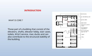
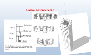
WHAT IS CORE?
Those part of a building that consist of the
elevators, shafts, elevator lobby, stair cases,
toilets, M & E service, riser, ducks and can
also contribute to the structural stability of
the building
INTRODUCTION
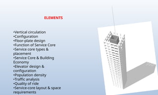
84.
•Vertical circulation
•Configuration
•Floor-plate design
•Functionof Service Core
•Service core types &
placement
•Service Core & Building
Economy
•Elevator design &
configuration
•Population density
•Traffic analysis
•Quality of ride
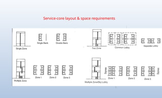
•Service-core layout & space
requirements
ELEMENTS
85.
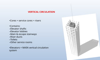
VERTICAL CIRCULATION
•Cores =service cores = risers
•Contains:
–Elevator shafts
–Elevator lobbies
–Main & escape stairways
–Riser-ducts
–Toilets
–Other service rooms
•Elevators = MAIN vertical circulation
system
86.
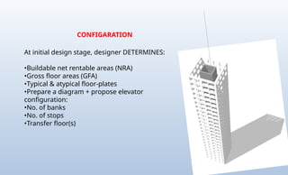
CONFIGARATION
At initial designstage, designer DETERMINES:
•Buildable net rentable areas (NRA)
•Gross floor areas (GFA)
•Typical & atypical floor-plates
•Prepare a diagram + propose elevator
configuration:
•No. of banks
•No. of stops
•Transfer floor(s)
87.
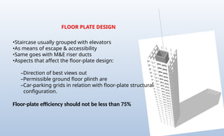
FLOOR PLATE DESIGN
•Staircaseusually grouped with elevators
•As means of escape & accessibility
•Same goes with M&E riser ducts
•Aspects that affect the floor-plate design:
–Direction of best views out
–Permissible ground floor plinth are
–Car-parking grids in relation with floor-plate structural
configuration.
Floor-plate efficiency should not be less than 75%
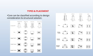
TYPES & PLACEMENT
•Corecan be classified according to design
consideration & structural solution.
90.
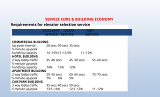
SERVICE CORE &BUILDING ECONOMY
COMMERCIAL BUILDING
Up-peak interval 28 secs 30 secs 35 secs
5-minute up-peak
handling capacity 14 -15%13 -13.5% 11 -12%
HOTEL BUILDING
2 way lobby traffic 35 -40 secs 45 -50 secs 55 -60 secs
5-minute up-peak
handling capacity 14% 13% 12%
APARTMENT BUILDING
2 way lobby traffic 50 -55 secs 60 -65 secs 70 -75 secs
5-minute up-peak 7% 6% 5%
CAR-PARK BUILDING
2 way lobby traffic 35 secs 40 secs 50 secs
5-minute up-peak 13.5 -14% 12.5 -13% 11 -12%
EXCELLENT GOOD FAIR
SERVICE SERVICE SERVICE
Requirements for elevator selection service
91.
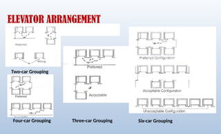
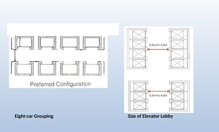
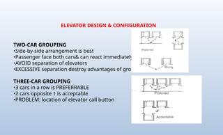
ELEVATOR DESIGN &CONFIGURATION
TWO-CAR GROUPING
•Side-by-side arrangement is best
•Passenger face both cars& can react immediately
•AVOID separation of elevators
•EXCESSIVE separation destroy advantages of group operation
THREE-CAR GROUPING
•3 cars in a row is PREFERRABLE
•2 cars opposite 1 is acceptable
•PROBLEM: location of elevator call button