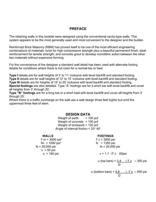
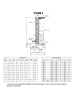
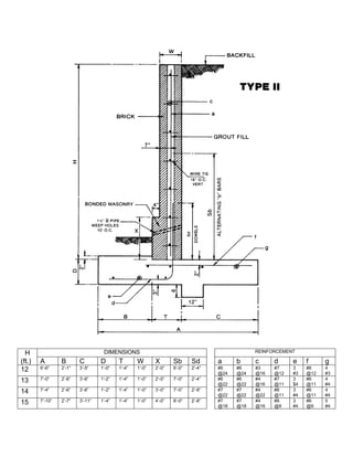
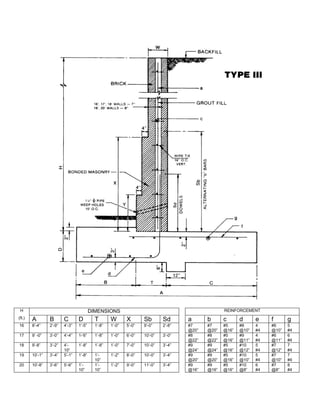
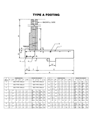
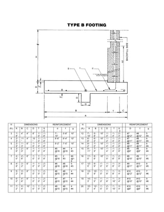
Reinforced
Brick
Masonry
Retaining
Walls
• Designs
• Specifications
• Construction Procedure
PREFACE
The retaining walls in this booklet were designed using the conventional cavity-type walls. This
system appears to be the most generally used and most convenient to the designer and the builder.
Reinforced Brick Masonry (RBM) has proved itself to be one of the most efficient engineering
combinations of materials: brick for high compressive strength plus a beautiful permanent finish; steel
reinforcement for tensile strength; and concrete grout to develop monolithic action between the other
two materials without expensive forming.
For the convenience of the designer a standard wall detail has been used with alternate footing
details for conditions where there is not room for a normal toe or heel.
Type I details are for wall heights of 3’ to 11’ inclusive with level backfill and standard footing.
Type II details are for wall heights of 12’ to 15’ inclusive with level backfill and standard footing.
Type III details are for heights of 16’ to 20’ inclusive with level backfill and standard footing.
Special footings are also detailed. Type “A” footings are for a short toe with level backfill and cover
all heights from 3’ through 20’.
Type “B” footings are for a long toe or a short heel with level backfill and cover all heights from 3’
through 20’.
Where there is a traffic surcharge on the wall use a wall design three feet higher but omit the
uppermost three feet of stem.
DESIGN DATA
Weight of earth = 100 pcf
Weight of concrete = 150 pcf
Weight of brickwork = 130 pcf
Angle of internal friction = 33° 40’
WALLS FOOTINGS
f’ m = 3000 psi* f’ c = 3000 psi
fm = 1000 psi* fc = 1350 psi
fs = 20,000 psi fs = 20,000 psi
v = 50 psi
u = 160 psi v = 1.1 √f’ c 60psi
u (top bars) = 3.4 √ f’ c < 350 psi
D
u (bottom bars) = 4.8 √ f’ c < 500 psi
D
100 pcf=1601,85 kg/m³
150 pcf=2402,77 kg/m³
130 pcf=2082,40 kg/m3
3000 psi = 20,68 Mpa
1350 psi = 9,308 MPa
60 psi = 0,41 MPa
20000 psi = 138 MPa
50 psi = 0,34 MPa
160 psi = 1,103 MPa
Overturn safety factors exceed 2.
Earth pressure due to overturn in all cases is less than 4000 psf.
Where footing keys are provided to resist sliding, passive earth resistance at the toe is ignored.
Tensile stress developed in the un-reinforced keys does not exceed 60 psi.
*See specifications for brick and mortar requirements.
Masonry and concrete designs in this booklet are based on standards developed by the Brick Institute
of America and by the American Concrete Institute.
The Brick Association of NC cannot be responsible for construction and function of a structure since
we provide no field construction supervision and have no knowledge of soil conditions or backfill
materials.
Designs and builders of these walls are cautioned not to exceed the loading conditions and working
strengths outlined in this booklet, and to strictly conform to specifications found on last page.
H DIMENSIONS REINFORCEMENT
(ft.) A B C D W Sb Sd a b c d E f g
3 1’-8” 4” 4” 8” 1’-0” 1’-8” #4*
@18”
#3
@16”
#5
@18”
2
#3
#3
@18”
2
#3
4 2’-3” 6” 9” 10” 1’-0” 1’-8” #4*
@18”
#3
@16”
#5
@18”
2
#3
#3
@18”
2
#3
5 2’-9” 9” 1’-0” 1’-0” 1’-0” 1’-8” #4*
@18”
#3
@16”
#5
@18”
2
#3
#3
@18”
2
#3
6 3’-3” 1’-1” 1’-2” 1’-0” 1’-0” 1’-8” #4*
@18”
#3
@16”
#5
@18”
2
#3
#3
@18”
2
#3
7 3’-9” 1’-3” 1’-6” 1’-0” 1’-0” 1’-8” #4*
@18”
#3
@16”
#5
@18”
2
#3
#4
@18”
2
#3
8 4’-3” 1’-6” 1’-9” 1’-0” 1’-0” 2’-0” #5
@18”
#3
@16”
#6
@18”
3
#3
#4
@18”
3
#3
9 4’-9” 1’-9” 2’-6” 1’-0” 1’-0” 2’-0” #5
@15”
#3
@16”
#6
@15”
3
#3
#4
@15”
3
#3
10 5’-3” 1’-9” 2’-6” 1’-0” 1’-0” 2’-4” #6
@18”
#3
@16”
#7
@15”
3
#3
#5
@15”
3
#3
11 5’10” 2’-0” 2’10” 1’-0” 1’-0” 6’-0” 2’-8” #7
@30”
#7
@30”
#3
@16”
#8
@15”
3
#3
#5
@15”
3
#3
* “d” bars may be extended full height of wall, eliminating “a” bars in these low wall heights, if
desired or convenient.
H DIMENSIONS REINFORCEMENT
(ft.) A B C D T W X Sb Sd a b c d e f g
12 6’-6” 2’-1” 3’-5” 1’-0” 1’-4” 1’-0” 2’-0” 6’-0” 2’-4” #6
@24
#6
@24
#3
@16
#7
@12
3
#3
#6
@12
4
#3
13 7’-0” 2’-6” 3’-6” 1’-2” 1’-4” 1’-0” 2’-0” 7’-0” 2’-4” #6
@22
#6
@22
#4
@16
#7
@11
3
$4
#6
@11
4
#4
14 7’-4” 2’-6” 3’-6” 1’-2” 1’-4” 1’-0” 3’-0” 7’-0” 2’-8” #7
@22
#7
@22
#4
@22
#8
@11
3
#4
#6
@11
4
#4
15 7’-10” 2’-7” 3’-11” 1’-4” 1’-4” 1’-0” 4’-0” 8’-0” 2’-8” #7
@18
#7
@18
#4
@16
#8
@9
3
#4
#6
@9
5
#4
H DIMENSIONS REINFORCEMENT
(ft.) A B C D T W X Sb Sd a b c d e f g
16 8’-4” 2’-9” 4’-3” 1’-5” 1’-8” 1’-0” 5’-0” 9’-0” 2’-8” #7
@20”
#7
@20”
#5
@16”
#8
@10”
4
#4
#6
@10”
5
#4
17 9’ -0” 3’-0” 4’-4” 1-‘6” 1’-8” 1’-0” 6’-0” 10’-0” 3’-0” #8
@22”
#8
@22”
#5
@16”
#9
@11”
4
#4
#6
@11”
6
#4
18 9’-8” 3’-2” 4’-
10”
1’-8” 1’-8” 1’-0” 7’-0” 10’-0” 3’-4” #9
@24”
#9
@24”
#5
@16”
#10
@12”
5
#4
#7
@12”
7
#4
19 10’-1” 3’-4” 5’-1” 1’-8” 1’-
10”
1’-2” 8’-0” 10’-0” 3’-4” #9
@20”
#9
@20”
#5
@16”
#10
@10”
5
#4
#7
@10”
7
#4
20 10’-8” 3’-6” 5’-6” 1’-
10”
1’-
10”
1’-2” 9’-0” 11’-0” 3’-4” #9
@16”
#9
@16”
#5
@16”
#10
@8”
6
#4
#7
@8”
8
#4
H DIMENSIONS REINFORCEMENT H DIMENSIONS REINFORCEMENT
(ft.) A B C D T Sd d e f g (ft.) A B C D T Sd d e f g
3 SEE TYPE I WALLS SEE TYPE I WALLS 12 7’-
4”
6” 5’-
6”
1-
‘2”
1’-
4”
2’-
4”
#7
@12”
2
#4
#7
@12”
5
#4
4 SEE TYPE I WALLS SEE TYPE I WALLS 13 7’-
6”
6” 5’-
8”
1’-
2”
1’-
4”
2’-
8”
#7
@11”
2
#4
#7
@ll”
5
#4
5 SEE TYPE I WALLS SEE TYPE I WALLS 14 7’-
10”
8” 5’-
10”
1’-
4”
1-
‘4”
2’-
8”
#8
@11”
2
#4
#7
@11”
6
#4
6 3’-
6”
6” 2’-
0”
1’-
0”
1’-
0”
1’-
8”
#5
@18”
2
#3
#3
@18
3
#3
15 8’-
4”
10” 6’-
2”
1’-
7”
1’-
4”
2-
8”
#8
@9”
2
#4
#7
@9”
7
#4
7 4’-
0”
6” 2’-
6”
1’-
0”
1’-
0”
1’-
8”
#5
@18”
2
#3
#4
@18
3
#3
16 9’-
4”
10” 6’-
10”
1’-
8”
1’-
8”
2’-
8”
#8
@10”
2
#5
#8
@10”
5
#5
8 4’-
8”
6” 3’-
2”
1’-
0”
1’-
0”
2’-
0”
#6
@18”
2
#3
#5
@18
4
#3
17 9’-
10”
10” 7’-
4”
1’-
8”
1’-
8”
3’-
0”
#9
@11”
2
#5
#9
@11”
6
#5
9 5’-
2”
6” 3’-
8”
1’-
0”
1’-
0”
2’-
0”
#6
@15”
2
#3
#5
@15
5
#3
18 10’
-9”
1’-
0”
8’-
1”
1’-
10”
1’-
8”
3’-
4”
#10
@12”
2
#5
#9
@12”
6
#5
10 6’-
0”
6” 4’-
6”
1’-
0”
1’-
0”
2’-
4”
#7
@15”
2
#4
#6
@15
3
#4
19 11’
-4”
1’-
0”
8’-
6”
1’-
10”
1’-
10”
3’-
4”
@10
@10”
2
#5
#9
@10”
7
#5
11 6’-
6”
6” 5’-
0”
1’-
2”
1’-
0”
2’-
8”
#8
@15”
2
#4
#7
@15
4
#4
20 12’
-1”
1’-
0”
9’-
3”
2’-
0”
1’-
10”
3’-
4”
#10
@8”
2
#5
#9
@8”
8
#5
H DIMENSIONS REINFORCEMENT H DIMENSIONS REINFORCEMENT
(ft.) A B C D T S
d
d f g (ft.) A B C D T S
d
D f g
3 1’-
8”
4” 4” 8” 1’-
0”
1’-
8”
7’-
10”
5’-8” 10” 12 7’-
10”
5’-
8”
10” 1’-
0”
1’-
4”
2’-
4”
#7
@12”
#8
@12”
5
#4
4 2’-
3”
11
”
4” 10
”
1’-
0”
1’-
8”
8’-6” 6’-4” 10” 13 8’-
6”
6’-
4”
10” 1’-
2”
1’-
4”
2’-
8”
#7
@11”
#8
@11”
6
#4
5 2’-
9”
1’-
3”
6” 1’-
0”
1’-
0”
1’-
8”
9’-2” 7’-0” 10” 14 9’-
2”
7’-
0”
10” 1’-
4”
1’-
4”
2’-
8”
#8
@11”
#8
@11”
6
#4
6 3’-
6”
2’-
0”
6” 1’-
0”
1’-
0”
1’-
8”
#5
@18
”
#4
@18
”
4
#3
15 9’-
11”
7’-
9”
10” 1’-
4”
1’-
4”
2-
8”
#8
@9”
#8
@9”
8
#4
7 4’-
0”
2’-
6”
6” 1’-
0”
1’-
0”
1’-
8”
#5
@18
”
2
#3
#4
@1
8
16 11’-
0”
8’-
6”
10” 1’-
5”
1’-
8”
2’-
8”
#8
@10”
#9
@10”
7
#5
8 4’-
8”
3’-
2”
6” 1’-
0”
1’-
0”
2’-
0”
#6
@18
”
#6
@18
”
5
#3
17 12’-
5”
9’-
9”
1’-
0”
1’-
6”
1’-
8”
3’-
0”
#9
@11”
#10
@11”
8
#5
9 5’-
2”
3’-
8”
6” 1’-
0”
1’-
0”
2’-
0”
#6
@15
”
#6
@15
”
4
#4
18 13’-
5”
10’-
9”
1’-
0”
1’-
8”
1’-
8”
3’-
4”
#10
@12”
#10
@12”
7
#6
10 6’-
0”
4’-
6”
6” 1’-
0”
1’-
0”
2’-
4”
#7
@15
”
#7
@15
”
4
#4
19 14’-
3”
11’-
5”
1’-
0”
1’-
8”
1’-
10”
3’-
4”
#10
@10”
#10
@10”
9
#6
11 7’-
2”
5’-
4”
10” 1’-
0”
1’-
0”
2’-
8”
#8
@15
”
#8
@15
”
4
#4
20 15’-
2”
12’-
4”
1’-
0”
2’-
0”
1’-
10”
3’-
4”
#10
@8”
#10
@8”
9
#6
RECOMMENDED SPECIFICATIONS
REINFORCED BRICK MASONRY RETAINING WALLS
Reinforced brick masonry allows the designer to use much higher working stresses than with plain masonry. Because
these higher working stresses are used, it is very important that the builder does not substitute any materials or methods
for those specified by the designer.
BRICK: Brick shall be of clay or shale, hard-burned, conforming to ASTM C62 or C216, Grade SW. In addition, they shall
have an average unit compressive strength of not less than 10,000 psi, or a prism strength of 3,000 psi. Color of brick
shall be approved by designer in advance of construction.
MORTAR: Mortar shall conform to ASTM C270, Type S. No mortar additives of any kind shall be used, without consent of
the designer in writing.
GROUT: Grout shall conform to ASTM Specification C476 and shall be proportioned 1 part Portland cement, 2 _ parts
sand, and 1 _ parts coarse aggregate, maximum size 3/8 in., all parts by volume. Sufficient water shall be added to
provide a fluid mix.
REINFORCING BARS: Bars shall conform to ASTM A-615, Grade 60. All deformations, splices, hooks and bends shall
conform to provisions of Building Code Requirements for Masonry Structures (ACI 530-95/ASCE 5-95/TMS 402-95).
CONCRETE: Footing concrete shall test 3,000 psi in compression at 28 days.
EXPANSION JOINTS: Expansion joints should be placed at corners, offsets in alignment, changes in wall thickness and
height, and at frequent intervals (to be determined by designer) in long straight walls. Horizontal reinforcing steel and
continuous wire ties/joint reinforcement must be interrupted at expansion joints. Expansion joints are to be continuous
through the cantilever footing.
PROCEDURE: All joints in brickwork shall be completely filled. Brick shall be wetted when necessary to reduce the rate of
suction. Horizontal joint reinforcement shall be placed in the wall at 16” on center vertically. Grout core of the wall must be
kept clean and free of mortar droppings. All exposed joints shall be tooled with a concave jointer when mortar is thumb
print hard.
Grouting may proceed after cavity of wall has been cleared of excess mortar and vertical steel has been set and secured.
Grout shall be poured in lifts not exceeding 4 feet under normal conditions. Grout shall have an 8 _” to 10” slump in order
to have sufficient fluidity to immediately surround steel, moisten brickwork and settle to a generally uniform level. All grout
shall be puddle or vibrated as work progresses.
GENERAL: back surface of the wall shall be damp-proof with a bituminous material or other approved system, covering
masonry from footing to finished grade. To provide for backfill drainage, weep holes shall be installed as shown on plans,
or parallel drain lines shall be installed.
A minimum of 12 inches (thickness) of coarse aggregate shall be placed against the wall as backfilling progresses from
footing to a point near finished grade.
In lieu of installing coarse aggregate, a prefabricated filter/drainage fabric system may be used to collect water from
backfill, relieving hydrostatic pressure.
Bottom of footing shall extend below customary frost line.
Brick Association of the Carolinas
800-62-BRICK

Reinforced brick masonry retaining walls

  • 1.
  • 2.
    PREFACE The retaining wallsin this booklet were designed using the conventional cavity-type walls. This system appears to be the most generally used and most convenient to the designer and the builder. Reinforced Brick Masonry (RBM) has proved itself to be one of the most efficient engineering combinations of materials: brick for high compressive strength plus a beautiful permanent finish; steel reinforcement for tensile strength; and concrete grout to develop monolithic action between the other two materials without expensive forming. For the convenience of the designer a standard wall detail has been used with alternate footing details for conditions where there is not room for a normal toe or heel. Type I details are for wall heights of 3’ to 11’ inclusive with level backfill and standard footing. Type II details are for wall heights of 12’ to 15’ inclusive with level backfill and standard footing. Type III details are for heights of 16’ to 20’ inclusive with level backfill and standard footing. Special footings are also detailed. Type “A” footings are for a short toe with level backfill and cover all heights from 3’ through 20’. Type “B” footings are for a long toe or a short heel with level backfill and cover all heights from 3’ through 20’. Where there is a traffic surcharge on the wall use a wall design three feet higher but omit the uppermost three feet of stem. DESIGN DATA Weight of earth = 100 pcf Weight of concrete = 150 pcf Weight of brickwork = 130 pcf Angle of internal friction = 33° 40’ WALLS FOOTINGS f’ m = 3000 psi* f’ c = 3000 psi fm = 1000 psi* fc = 1350 psi fs = 20,000 psi fs = 20,000 psi v = 50 psi u = 160 psi v = 1.1 √f’ c 60psi u (top bars) = 3.4 √ f’ c < 350 psi D u (bottom bars) = 4.8 √ f’ c < 500 psi D 100 pcf=1601,85 kg/m³ 150 pcf=2402,77 kg/m³ 130 pcf=2082,40 kg/m3 3000 psi = 20,68 Mpa 1350 psi = 9,308 MPa 60 psi = 0,41 MPa 20000 psi = 138 MPa 50 psi = 0,34 MPa 160 psi = 1,103 MPa
  • 3.
    Overturn safety factorsexceed 2. Earth pressure due to overturn in all cases is less than 4000 psf. Where footing keys are provided to resist sliding, passive earth resistance at the toe is ignored. Tensile stress developed in the un-reinforced keys does not exceed 60 psi. *See specifications for brick and mortar requirements. Masonry and concrete designs in this booklet are based on standards developed by the Brick Institute of America and by the American Concrete Institute. The Brick Association of NC cannot be responsible for construction and function of a structure since we provide no field construction supervision and have no knowledge of soil conditions or backfill materials. Designs and builders of these walls are cautioned not to exceed the loading conditions and working strengths outlined in this booklet, and to strictly conform to specifications found on last page.
  • 4.
    H DIMENSIONS REINFORCEMENT (ft.)A B C D W Sb Sd a b c d E f g 3 1’-8” 4” 4” 8” 1’-0” 1’-8” #4* @18” #3 @16” #5 @18” 2 #3 #3 @18” 2 #3 4 2’-3” 6” 9” 10” 1’-0” 1’-8” #4* @18” #3 @16” #5 @18” 2 #3 #3 @18” 2 #3 5 2’-9” 9” 1’-0” 1’-0” 1’-0” 1’-8” #4* @18” #3 @16” #5 @18” 2 #3 #3 @18” 2 #3 6 3’-3” 1’-1” 1’-2” 1’-0” 1’-0” 1’-8” #4* @18” #3 @16” #5 @18” 2 #3 #3 @18” 2 #3 7 3’-9” 1’-3” 1’-6” 1’-0” 1’-0” 1’-8” #4* @18” #3 @16” #5 @18” 2 #3 #4 @18” 2 #3 8 4’-3” 1’-6” 1’-9” 1’-0” 1’-0” 2’-0” #5 @18” #3 @16” #6 @18” 3 #3 #4 @18” 3 #3 9 4’-9” 1’-9” 2’-6” 1’-0” 1’-0” 2’-0” #5 @15” #3 @16” #6 @15” 3 #3 #4 @15” 3 #3 10 5’-3” 1’-9” 2’-6” 1’-0” 1’-0” 2’-4” #6 @18” #3 @16” #7 @15” 3 #3 #5 @15” 3 #3 11 5’10” 2’-0” 2’10” 1’-0” 1’-0” 6’-0” 2’-8” #7 @30” #7 @30” #3 @16” #8 @15” 3 #3 #5 @15” 3 #3 * “d” bars may be extended full height of wall, eliminating “a” bars in these low wall heights, if desired or convenient.
  • 5.
    H DIMENSIONS REINFORCEMENT (ft.)A B C D T W X Sb Sd a b c d e f g 12 6’-6” 2’-1” 3’-5” 1’-0” 1’-4” 1’-0” 2’-0” 6’-0” 2’-4” #6 @24 #6 @24 #3 @16 #7 @12 3 #3 #6 @12 4 #3 13 7’-0” 2’-6” 3’-6” 1’-2” 1’-4” 1’-0” 2’-0” 7’-0” 2’-4” #6 @22 #6 @22 #4 @16 #7 @11 3 $4 #6 @11 4 #4 14 7’-4” 2’-6” 3’-6” 1’-2” 1’-4” 1’-0” 3’-0” 7’-0” 2’-8” #7 @22 #7 @22 #4 @22 #8 @11 3 #4 #6 @11 4 #4 15 7’-10” 2’-7” 3’-11” 1’-4” 1’-4” 1’-0” 4’-0” 8’-0” 2’-8” #7 @18 #7 @18 #4 @16 #8 @9 3 #4 #6 @9 5 #4
  • 6.
    H DIMENSIONS REINFORCEMENT (ft.)A B C D T W X Sb Sd a b c d e f g 16 8’-4” 2’-9” 4’-3” 1’-5” 1’-8” 1’-0” 5’-0” 9’-0” 2’-8” #7 @20” #7 @20” #5 @16” #8 @10” 4 #4 #6 @10” 5 #4 17 9’ -0” 3’-0” 4’-4” 1-‘6” 1’-8” 1’-0” 6’-0” 10’-0” 3’-0” #8 @22” #8 @22” #5 @16” #9 @11” 4 #4 #6 @11” 6 #4 18 9’-8” 3’-2” 4’- 10” 1’-8” 1’-8” 1’-0” 7’-0” 10’-0” 3’-4” #9 @24” #9 @24” #5 @16” #10 @12” 5 #4 #7 @12” 7 #4 19 10’-1” 3’-4” 5’-1” 1’-8” 1’- 10” 1’-2” 8’-0” 10’-0” 3’-4” #9 @20” #9 @20” #5 @16” #10 @10” 5 #4 #7 @10” 7 #4 20 10’-8” 3’-6” 5’-6” 1’- 10” 1’- 10” 1’-2” 9’-0” 11’-0” 3’-4” #9 @16” #9 @16” #5 @16” #10 @8” 6 #4 #7 @8” 8 #4
  • 7.
    H DIMENSIONS REINFORCEMENTH DIMENSIONS REINFORCEMENT (ft.) A B C D T Sd d e f g (ft.) A B C D T Sd d e f g 3 SEE TYPE I WALLS SEE TYPE I WALLS 12 7’- 4” 6” 5’- 6” 1- ‘2” 1’- 4” 2’- 4” #7 @12” 2 #4 #7 @12” 5 #4 4 SEE TYPE I WALLS SEE TYPE I WALLS 13 7’- 6” 6” 5’- 8” 1’- 2” 1’- 4” 2’- 8” #7 @11” 2 #4 #7 @ll” 5 #4 5 SEE TYPE I WALLS SEE TYPE I WALLS 14 7’- 10” 8” 5’- 10” 1’- 4” 1- ‘4” 2’- 8” #8 @11” 2 #4 #7 @11” 6 #4 6 3’- 6” 6” 2’- 0” 1’- 0” 1’- 0” 1’- 8” #5 @18” 2 #3 #3 @18 3 #3 15 8’- 4” 10” 6’- 2” 1’- 7” 1’- 4” 2- 8” #8 @9” 2 #4 #7 @9” 7 #4 7 4’- 0” 6” 2’- 6” 1’- 0” 1’- 0” 1’- 8” #5 @18” 2 #3 #4 @18 3 #3 16 9’- 4” 10” 6’- 10” 1’- 8” 1’- 8” 2’- 8” #8 @10” 2 #5 #8 @10” 5 #5 8 4’- 8” 6” 3’- 2” 1’- 0” 1’- 0” 2’- 0” #6 @18” 2 #3 #5 @18 4 #3 17 9’- 10” 10” 7’- 4” 1’- 8” 1’- 8” 3’- 0” #9 @11” 2 #5 #9 @11” 6 #5 9 5’- 2” 6” 3’- 8” 1’- 0” 1’- 0” 2’- 0” #6 @15” 2 #3 #5 @15 5 #3 18 10’ -9” 1’- 0” 8’- 1” 1’- 10” 1’- 8” 3’- 4” #10 @12” 2 #5 #9 @12” 6 #5 10 6’- 0” 6” 4’- 6” 1’- 0” 1’- 0” 2’- 4” #7 @15” 2 #4 #6 @15 3 #4 19 11’ -4” 1’- 0” 8’- 6” 1’- 10” 1’- 10” 3’- 4” @10 @10” 2 #5 #9 @10” 7 #5 11 6’- 6” 6” 5’- 0” 1’- 2” 1’- 0” 2’- 8” #8 @15” 2 #4 #7 @15 4 #4 20 12’ -1” 1’- 0” 9’- 3” 2’- 0” 1’- 10” 3’- 4” #10 @8” 2 #5 #9 @8” 8 #5
  • 8.
    H DIMENSIONS REINFORCEMENTH DIMENSIONS REINFORCEMENT (ft.) A B C D T S d d f g (ft.) A B C D T S d D f g 3 1’- 8” 4” 4” 8” 1’- 0” 1’- 8” 7’- 10” 5’-8” 10” 12 7’- 10” 5’- 8” 10” 1’- 0” 1’- 4” 2’- 4” #7 @12” #8 @12” 5 #4 4 2’- 3” 11 ” 4” 10 ” 1’- 0” 1’- 8” 8’-6” 6’-4” 10” 13 8’- 6” 6’- 4” 10” 1’- 2” 1’- 4” 2’- 8” #7 @11” #8 @11” 6 #4 5 2’- 9” 1’- 3” 6” 1’- 0” 1’- 0” 1’- 8” 9’-2” 7’-0” 10” 14 9’- 2” 7’- 0” 10” 1’- 4” 1’- 4” 2’- 8” #8 @11” #8 @11” 6 #4 6 3’- 6” 2’- 0” 6” 1’- 0” 1’- 0” 1’- 8” #5 @18 ” #4 @18 ” 4 #3 15 9’- 11” 7’- 9” 10” 1’- 4” 1’- 4” 2- 8” #8 @9” #8 @9” 8 #4 7 4’- 0” 2’- 6” 6” 1’- 0” 1’- 0” 1’- 8” #5 @18 ” 2 #3 #4 @1 8 16 11’- 0” 8’- 6” 10” 1’- 5” 1’- 8” 2’- 8” #8 @10” #9 @10” 7 #5 8 4’- 8” 3’- 2” 6” 1’- 0” 1’- 0” 2’- 0” #6 @18 ” #6 @18 ” 5 #3 17 12’- 5” 9’- 9” 1’- 0” 1’- 6” 1’- 8” 3’- 0” #9 @11” #10 @11” 8 #5 9 5’- 2” 3’- 8” 6” 1’- 0” 1’- 0” 2’- 0” #6 @15 ” #6 @15 ” 4 #4 18 13’- 5” 10’- 9” 1’- 0” 1’- 8” 1’- 8” 3’- 4” #10 @12” #10 @12” 7 #6 10 6’- 0” 4’- 6” 6” 1’- 0” 1’- 0” 2’- 4” #7 @15 ” #7 @15 ” 4 #4 19 14’- 3” 11’- 5” 1’- 0” 1’- 8” 1’- 10” 3’- 4” #10 @10” #10 @10” 9 #6 11 7’- 2” 5’- 4” 10” 1’- 0” 1’- 0” 2’- 8” #8 @15 ” #8 @15 ” 4 #4 20 15’- 2” 12’- 4” 1’- 0” 2’- 0” 1’- 10” 3’- 4” #10 @8” #10 @8” 9 #6
  • 9.
    RECOMMENDED SPECIFICATIONS REINFORCED BRICKMASONRY RETAINING WALLS Reinforced brick masonry allows the designer to use much higher working stresses than with plain masonry. Because these higher working stresses are used, it is very important that the builder does not substitute any materials or methods for those specified by the designer. BRICK: Brick shall be of clay or shale, hard-burned, conforming to ASTM C62 or C216, Grade SW. In addition, they shall have an average unit compressive strength of not less than 10,000 psi, or a prism strength of 3,000 psi. Color of brick shall be approved by designer in advance of construction. MORTAR: Mortar shall conform to ASTM C270, Type S. No mortar additives of any kind shall be used, without consent of the designer in writing. GROUT: Grout shall conform to ASTM Specification C476 and shall be proportioned 1 part Portland cement, 2 _ parts sand, and 1 _ parts coarse aggregate, maximum size 3/8 in., all parts by volume. Sufficient water shall be added to provide a fluid mix. REINFORCING BARS: Bars shall conform to ASTM A-615, Grade 60. All deformations, splices, hooks and bends shall conform to provisions of Building Code Requirements for Masonry Structures (ACI 530-95/ASCE 5-95/TMS 402-95). CONCRETE: Footing concrete shall test 3,000 psi in compression at 28 days. EXPANSION JOINTS: Expansion joints should be placed at corners, offsets in alignment, changes in wall thickness and height, and at frequent intervals (to be determined by designer) in long straight walls. Horizontal reinforcing steel and continuous wire ties/joint reinforcement must be interrupted at expansion joints. Expansion joints are to be continuous through the cantilever footing. PROCEDURE: All joints in brickwork shall be completely filled. Brick shall be wetted when necessary to reduce the rate of suction. Horizontal joint reinforcement shall be placed in the wall at 16” on center vertically. Grout core of the wall must be kept clean and free of mortar droppings. All exposed joints shall be tooled with a concave jointer when mortar is thumb print hard. Grouting may proceed after cavity of wall has been cleared of excess mortar and vertical steel has been set and secured. Grout shall be poured in lifts not exceeding 4 feet under normal conditions. Grout shall have an 8 _” to 10” slump in order to have sufficient fluidity to immediately surround steel, moisten brickwork and settle to a generally uniform level. All grout shall be puddle or vibrated as work progresses. GENERAL: back surface of the wall shall be damp-proof with a bituminous material or other approved system, covering masonry from footing to finished grade. To provide for backfill drainage, weep holes shall be installed as shown on plans, or parallel drain lines shall be installed. A minimum of 12 inches (thickness) of coarse aggregate shall be placed against the wall as backfilling progresses from footing to a point near finished grade. In lieu of installing coarse aggregate, a prefabricated filter/drainage fabric system may be used to collect water from backfill, relieving hydrostatic pressure. Bottom of footing shall extend below customary frost line.
  • 10.
    Brick Association ofthe Carolinas 800-62-BRICK