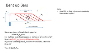
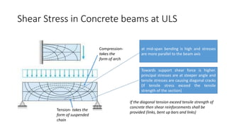
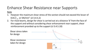
This document discusses the design of shear reinforcement in reinforced concrete beams according to BS8110. It explains that shear stresses cause diagonal cracking if they exceed the tensile strength of the concrete. Shear reinforcement such as links and bent-up bars are required to resist shear stresses beyond the concrete's capacity. Design of shear reinforcement involves calculating the shear resistance provided by the concrete and steel reinforcement. The spacing and arrangement of shear links and bars must satisfy code requirements to effectively resist diagonal cracking.


![Design of Shear Links
Sv Sv
Sv
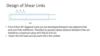
V =resistance due to concrete +Resistance due to reinforcements
= (concrete stress x area) + (Steel stress x area of links)
The force in each link = [
𝑓𝑦𝑣
ɣ𝑚
Asv]= 0.87fyv.Asv
number of links cut by 45o plane = d/sv
Total force in the cut links = 0.87fyv.Asv. d/sv
V=vcbvd+ 0.87fyv.Asv. d/sv
0.87fyv.Asv. = [V-vcbvd].sv/d=[vbvd- vcbvd] sv/d=[bvsv(v-vc)]
as V=vbvd
Hence
x
x
d
d
V
bv
d
Asv
As
Asv ≥
𝑏𝑣
𝑠𝑣
(𝑣−𝑣𝑐)
0.87𝑓𝑦𝑣](https://image.slidesharecdn.com/4sheardesign-231018100356-32087d4c/85/4-shear-design-pptx-13-320.jpg)