This document summarizes recent developments in friction stir welding of aluminum alloys. Friction stir welding is a solid-state welding technique developed for joining difficult-to-weld aluminum alloys. It has been implemented commercially in industries like shipbuilding, train manufacturing, and aviation. The document reviews the microstructures and mechanical properties of friction stir welded aluminum alloys and how weld parameters influence these properties. It also discusses developments in friction stir welding tool designs and applications of the technique beyond aluminum alloys.
Friction Stir Welding of Magnesium Alloys - A Reviewmsejjournal
The selection of proper material for each application is a critical part in every manufacturing industry.
In the field of aerospace and automobile the major requirement is light weight yet strong material which
can possess every aspect of design parameters. Magnesium alloy one of the major raw material used in
these industries due to its light weight, good thermal conductivity etc. Also Friction stir welding is the
joining process that is being used in these industries as it is a solid state joining process. This paper
gives a detailed review about Friction Stir welding of Mg alloys. The review period is considered from
2009 to 2015.A detailed review about Friction stir welding of Mg alloys has not been done before in this
manner. This review work may be a ready reference for subsequent researchers.
Experimental Investigation of Friction Stir Welding Of Aluminum Aa6061 Alloy ...iosrjce
The combination of wrought aluminum-magnesium-silicon alloy confirming to aluminum AA6061
alloy widely accepted because of light weight fabrication structures, high strength to weight ratio and good
corrosion resistance. Friction Stir Welding(FSW) process is an emerging solid state joining process in which
the material that is being welded does not melt and recast when compared to fusion welding process that are
routinely used for joining structural aluminum alloys. In this FSW process a non consumable tool is used to
generate frictional heat in the abutting surfaces. Experiments for surface roughness, Rockwell hardness and
tensile tests are carried out and reported in this paper. The base material used for friction stir welding is
aluminum AA 6061 alloy. Surface roughness values decreases with the increase in speed of the tool and also
there exists an optimum speed to have the good surface finish. Hardness increases with decrease in speed of the
tool but increases after reaching a certain value. Tensile strength increases with the increase in speed of the
tool and also there exists an optimum values for particular feed of the tool.
FRICTION STIR WELDING is a very latest tchnology of welding process .Its a green method of solid state joining, and also a defect free method .
To know more about this you can also watch this animation https://youtu.be/kEEST5cgOao
A STUDY ON FRICTION STIR WELDING OF VARIOUS ALUMINIUM ALLOYSIJARIIT
The comprehensive body of knowledge that has built up with respect to the friction stir welding (FSW) of aluminum alloys since the technique was invented in 1991 is reviewed on this paper. The basic principles of FSW are described, including metal flow and thermal history, before discussing how process parameters affect the weld microstructure and the likelihood of defects. Finally, the range of mechanical properties that can be achieved is discussed. It is demonstrated that FSW of aluminum is becoming an increasingly mature technology with numerous commercial applications. Keywords - Friction stir welding, metal flow, process parameters, mechanical properties
Friction-stir welding is an advanced solid-state joining process (the metal is not melted) which involves the use of a third body tool to join two facing surfaces. Heat is generated between the tool and material which leads to a very soft region near the FSW tool. It then mechanically intermixes the two pieces of metal at the place of the joint, then the softened metal (due to the elevated temperature) can be joined using mechanical pressure (which is applied by the tool), much like joining clay, or dough. It is primarily used on aluminium, and most often on extruded aluminium (non-heat treatable alloys), and on structures which need superior weld strength without a post weld heat treatment.
It was invented and experimentally proven at The Welding Institute UK in December 1991.
FRICTION STIR WELDING OF ALUMINIUM ALLOYS - A REVIEWIAEME Publication
This welding is a novel process used to join metallic alloys. Friction stir welding is in vogue in aerospace, automotive and other industrial establishments for connecting alloys like aluminum, magnesium and copper. Rotational speed, welding speed and the angle of attack are important in the process of FSW. They analyze the weld quality. FSW produces stronger weld joint then the original material in selected parameters. FSW is a solid-state process, where metal is not melted uses a cylindrical shouldered tool with a profiled pin rotated and gradually plunged into the weld joint between two metal parts of plate or sheet that are to be welded together.
Fsw optimization for dissimilar aluminium alloys (Presentation)Dr. Bikram Jit Singh
The basic principle of FSW involves simultaneous application of pressure and relative motion, generally in a rotational mode, between the components to be joined. From the available literature, it has been observed that the effect of welding parameters on desired characteristics was determined by taking into consideration one parameter at a time or by using conventional methods like, One Factor at a Time (OFAT) technique. So without ignoring the limitations of earlier researches, the main focus in this study has been kept on welding of dissimilar alloys (specifically AA6061 and AA5086) by using Design of Experiments (DoE) which is quite rarely used Multi-Factor at a Time (MFAT) technique. Therefore, the ultimate objective of the work is to optimize critical to process parameters (CPPs) of FSW process for achieving mechanical characteristics within ranges. This book contains quite rare information as far as FSW is concerned.
Effects and defects of the polypropylene plate for different parameters in fr...eSAT Publishing House
IJRET : International Journal of Research in Engineering and Technology is an international peer reviewed, online journal published by eSAT Publishing House for the enhancement of research in various disciplines of Engineering and Technology. The aim and scope of the journal is to provide an academic medium and an important reference for the advancement and dissemination of research results that support high-level learning, teaching and research in the fields of Engineering and Technology. We bring together Scientists, Academician, Field Engineers, Scholars and Students of related fields of Engineering and Technology.
Characterization and processing of friction stir welding on copper weldseSAT Journals
Abstract FSW(Friction Stir Welding) is a welding technology will be a part of different metals with sensible properties. During this paper, fsw attachment b/n steel, aluminum and copper plates with thicknesses of 3 millimeter was welded. Here we tend to had considered completely different completely different} materials with different combinations i.e copper and copper, copper and aluminum, aluminum & stainless steel, stainless steel & copper. Friction Stir Welding experiments were employed to get the good wieldable properties by maintaining the rpm speeds to 1120 revolutions per minute and attachment speed within the limit of 14-112 mm/min and here we can adjust the pin profile of the location respect to the line butt. Micro struc analysis can be done for examine the parent and the welded material. Cutting and sectioning of the welded pieces for metallographic analysis of the planes which are perpendicular for the attachment and the travelling direction & which is parallel to the friction welding was done. Here the mechanical properties of welding which was were determined by employing the same standard micro hardness and also tensile hardness testing and finding the maximum elongation of the metals to the properties of fsw. From experimental fsw process it can be found the pin profile and also the rotational speed, feed is an important in manufacturing of free welds in fsw of aluminum, copper and steel. Key Words: FSW, Aluminum, copper, stainless steel.
Optimization of friction stir welding process parameter using taguchi method ...eSAT Journals
Abstract Friction stir welding (FSW) is relatively new solid state joining process. This joining technique is energy efficient, environment friendly and versatile. Welding is a multiinput-output process in which quality of welded joint is depends upon a input parameter. Therefore optimization of input process parameter is required to achieve good quality of welding. There are so many methods of optimization in which Taguchi method and Response surface methodology are selected for optimization of process parameter. In this review the effect of process parameter on welded joint studied and optimizes the parameter by using Taguchi method and Response surface methodology. The study of Friction stir welding of Aluminium alloy and High density polyethylene sheets shows the improvement in welded joint quality by optimization of process parameter. The main process parameters which affect the strength of welded joint is tool rotational speed, welding speed, axial force and tool pin profile. Keywords: Friction stir welding (FSW), Optimization, Taguchi Method Response surface Methodology Prediction models
A Review on Effect of Process Parameters on Tensile Strength of Friction Stir...ijsrd.com
Friction stir welding (FSW) is an innovative solid state joining process. This paper discuss about the friction stir welding of joining heat treated aluminum alloys for Aerospace and Automobile industries. These welded joints have higher tensile strength to weight ratio and finer micro structure. FSW of aluminum alloys have the potential to hold good mechanical and metallurgical properties. An attempt is made to determine and evaluate the influence of the process parameters of FSW on the weldments. The aim of this study was to investigate the effect of process parameters on the tensile strength of the welded joints.
Friction Stir welding combine the action of frictional heating and mechanical deformation due to a rotating tool. The advantages of Friction Stir welding over arc welding is as follows:-
1) High quality weld can be achieved
2) Absence of solidification cracking
3) Lower apparent energy input
4) Less distortion and residual stress
Solar tracking system, Full Report Submitted in B.Tech, Electrical & Electronics Engineering Final Year @ College of Engineering Roorkee-247667, Uttarakhand, INDIA.
Modeling and Simulation of Base Plate of Friction Stir Welding-Advanced Weldi...ijsrd.com
Friction stir processing is an emerging technique based on the principles of friction stir welding (FSW). It is a solid-state joining method that is energy efficient, environmentally friendly, and versatile. It is considered by many to be the most significant development in metal joining in a decade. The basic concept of friction stir processing is remarkably simple. A rotating tool with pin and shoulder is inserted in the material to be joined, and traversed along the line of interest. The heating is localized, and is generated by friction between the tool and the work piece, with additional adiabatic heating from metal deformation. A processed zone is produced by movement of material from the front of the pin to the back of the pin.
Through this paper an attempt is made to study and review a special welding technology of friction stir welding (FSW) which is a solid-state joining process. Friction Stir Welding (FSW) is a recent advanced technique, invented by The Welding Institute (TWI) in 1991, that utilizes a nonconsumable rotating welding tool to generate frictional heat and plastic deformation at the welding location; thereby, affecting the formation of a joint while the material is in the solid state. In particular, FSW can be used to join high-strength aerospace aluminum alloys and other high temperature metallic alloys that are difficult to weld by conventional fusion welding method. FSW is considered to be the most significant development in metal joining process in a decade The comprehensive body of knowledge that has built up with respect to the friction stir welding (FSW) of aluminum alloys. This study addresses the current state of understanding and development of the FSW process. The principles of weld formation, welding parameters, design principles, including metal flow and thermal history, before discussing how process parameters affect the weld properties Danail Abdullah"A Review of Friction Stirs Welding" Published in International Journal of Trend in Scientific Research and Development (ijtsrd), ISSN: 2456-6470, Volume-1 | Issue-4 , June 2017, URL: http://www.ijtsrd.com/papers/ijtsrd124.pdf http://www.ijtsrd.com/engineering/mechanical-engineering/124/a-review-of-friction-stirs-welding/danail-abdullah
Clinching as a Nonconventional Method to Join Drawing Quality Steel Sheetsijtsrd
The most common methods for joining the galvanized steel sheetsin automotive industry is resistance spot welding.These methods require some specific time-consuming pretreatment of joined materials and the protective layer is destroyed which lead to decreasing of corrosion resistance.Therefore, it is necessary to utilize the other joining methods. The contribution deals with analysis of properties of clinched joints. There were made samples with single press joint and various sheets orientation due to punch and die and also samples with double press joints. Deep drawing quality steels of U.S.SteelKošice, Ltd. productions of various thicknesses a quality were used. The steels are also used in automotive industry. Moreover carrying capacity of press joints was evaluated. Luboš Kašcák"Clinching as a Nonconventional Method to Join Drawing Quality Steel Sheets" Published in International Journal of Trend in Scientific Research and Development (ijtsrd), ISSN: 2456-6470, Volume-2 | Issue-1 , December 2017, URL: http://www.ijtsrd.com/papers/ijtsrd8243.pdf http://www.ijtsrd.com/other-scientific-research-area/other/8243/clinching-as-a-nonconventional-method-to-join-drawing-quality-steel-sheets/luboš-kašcák
Ahmed ibrahim razooqi -- study the microstructure and mechanical properties ...ahmed Ibrahim
Ahmed Ibrahim Razooqi ---
Study the microstructure and mechanical properties of dissimilar friction stir spot welding of carbon steel 1006 to aluminum alloy aa2024-t3.
Friction stir spot welding-FSSW has been suggested as effectual process to welding difficult materials such as dissimilar materials and
thin sheet of metal alloys. In this study, using dissimilar materials were welded carbon steel-1006 on upper plate and aluminum alloy
AA2024-T3 on lower plate. Macrostructure, micro-structural analysis and mechanical properties of the joints are done. The effect of
penetration depth, dwell time and spindle speed on tensile shear load are investigated with invariable of other parameter during welding
process. The maximum tensile shear load (3.31KN) was occurred when using 0.4mm of penetration depth, 10 sec of dwell time and 1400
rpm of spindle speed. Also, two type of failure shape was observed interfacial fracture of carbon steel sheet and pull -out fracture of
AA2024-T3 sheet.
Experimental Analysis to Optimize parameters of Friction Stir Welding of Alum...IJSRD
This paper is a review of research work in the last decade on friction stir welding. In many industrial applications steel is readily replaced by non-ferrous alloys like aluminum alloys. Aluminum alloys having good mechanical properties as equated structural steel and low weight that allows a significant reduction in weight. But the welding of aluminum alloys by regular processes can causes serious problems. The difficulties are like loss of alloying elements and presence of separation and porosities in the weld joint. Friction stir welding (FSW) is a solid state welding process, which removes all these problems of solidification related with the conventional fusion welding processes. In this research work an attempt has been made to develop an the relationship between FSW variables (tool rotation and tilt angle) and tensile strength and yield strength of number of pass friction stir welded aluminium alloy AA 6082 butt joints. Taguchi method is used for analysing the problem in which several independent variables influence the response. A three-parameter -three-level central composite design was used to determine the optimal factors of friction stir welding process for aluminium alloy.
A review paper on friction stir welding process parametersIJARIIT
Friction Stir Welding (FSW) was invented by Wayne Thomas at TWI (The Welding Institute), and the first patent
applications were filed in the UK in December 1991. Initially, the process was regarded as a “laboratory” curiosity, but it soon
became clear that FSW offers numerous benefits in the fabrication of aluminum products. Friction Stir Welding (FSW) has
become a major joining process in the aerospace, railway and ship building industries especially in the fabrication of aluminum
alloys. The process uses a spinning non-consumable tool to generate frictional heat in the work piece. Worldwide, there are now
over 135 licensees of FSW and new techniques and applications are being developed daily. This paper looks at the review, on
friction stir welding process, various welding variables like tool rotation, transverse speed, tool tilt, plunge depth and tool design,
for the welding of aluminum alloys or various dissimilar alloys. Applications, future aspects, and several key problems are also
described.
Verification of johnson cook material model constants of aa2024-t3 for use in...eSAT Publishing House
IJRET : International Journal of Research in Engineering and Technology is an international peer reviewed, online journal published by eSAT Publishing House for the enhancement of research in various disciplines of Engineering and Technology. The aim and scope of the journal is to provide an academic medium and an important reference for the advancement and dissemination of research results that support high-level learning, teaching and research in the fields of Engineering and Technology. We bring together Scientists, Academician, Field Engineers, Scholars and Students of related fields of Engineering and Technology
Alternative Joining Methods in Car Body Productiontheijes
The optimization of a car body in terms of cost can be achieved by using different materials in various positions of the car in order to utilize specific properties of each different material. The paper deals with the methods of mechanical joining used in car body production as alternatives to the most used conventional resistance spot welding. Load-bearing capacities of the joints made by mechanical joining and resistance spot welding of various materials used in car body structures are compared. The mechanical joining is mainly used to join material with various thicknesses, mechanical properties, surface coatings, even ferrous or non-ferrous metals.
ANALYSIS OF TOOL USED FOR FRICTION STIR SPOT WELDING BY EXPLICIT MESHING SCH...vivatechijri
FSSW is an advanced and popular solid-state material welding method, which has achieved a
different variety of popularity in service in industries and automotive. FSSW method (technique) is used for joining
similar or dissimilar materials like aluminium, titanium, magnesium and copper alloys etc. This paper presents
finite element modeling of friction stir spot welding (FSSW) process using Abaqus/Explicit as a finite element
solver. Three-dimensional coupled thermal-stress model was used to calculate thermo-mechanical response of
FSSW process. The various factors such as rotational speed, transverse speed and profile of the tool plays a very
significant role in the joining quality of material using FSSW.
The main target of this analysis is to observe the variation of tool profile and welding quality of Ti 6Al 4V alloy
as the tool speed varies. Two Ti 6Al 4V were lapped and provided with support to the bottom of the plate known
as a back anvil to constrain the motion. This is where we analyzed the material flow due to friction of heat
generation in the weld zone. Ti 6Al 4V is one of the most commonly used materials and its applications, where
low density and excellent corrosion is applied in a wide range of resistance, are necessary in industries such as
aerospace industry and biomechanical, marine, chemical industries, gas turbine, etc.
Experimental Investigation of Tensile Strength and Deflection Characteristics...IOSR Journals
Aluminum alloys are used in many applications in which the combination of high strength and low
weight is attractive; ship building, air frame, transportation industry etc. are some areas in which the low
weight can be significant value. Friction stir welding (FSW) is a new welding technique particularly well suited
to aluminum alloys though this technique is also used for other materials. Friction stir welding promises joints
with low porosity, fine microstructures, minimum phase transformation and low oxidation compared to
conventional welding techniques. It is capable of joining combinations of alloys not amenable to conventional
welding.Experiments for tensile and deflection tests were carried out and reported in this research paper. The
base material used for friction stir welding was AA 6351–T4 Aluminum alloy. Tensile strength and breaking
loads were increased with increase of rotational speed of the tool but it drops after attaining marginal speed.
Deflections of friction stir welded specimens and base materials were compared and they exhibited almost
similar trends at different load conditions and deflections of all the specimens were increased with increment of
load
Similar to Recent Developments in Friction Stir Welding of Al alloys (20)
Experimental Investigation of Tensile Strength and Deflection Characteristics...
Recent Developments in Friction Stir Welding of Al alloys
1. Recent Developments in Friction Stir Welding of Al-alloys
Gu¨rel C¸ am and Selcuk Mistikoglu
(Submitted January 21, 2014; in revised form March 12, 2014; published online April 8, 2014)
The diversity and never-ending desire for a better life standard result in a continuous development of the
existing manufacturing technologies. In line with these developments in the existing production technologies
the demand for more complex products increases, which also stimulates new approaches in production
routes of such products, e.g., novel welding procedures. For instance, the friction stir welding (FSW)
technology, developed for joining difficult-to-weld Al-alloys, has been implemented by industry in manu-
facturing of several products. There are also numerous attempts to apply this method to other materials
beyond Al-alloys. However, the process has not yet been implemented by industry for joining these
materials with the exception of some limited applications. The microstructures and mechanical properties
of friction stir welded Al-alloys existing in the open literature will be discussed in detail in this review. The
correlations between weld parameters used during FSW and the microstructures evolved in the weld region
and thus mechanical properties of the joints produced will be highlighted. However, the modeling studies,
material flow, texture formation and developments in tool design are out of the scope of this work as well as
the other variants of this technology, such as friction stir spot welding (FSSW).
Keywords Al-alloys, friction stir welding, grain refinement,
hardness loss, joining, joint performance
1. Introduction
Welding is a unique manufacturing method, which allows
the production of complex parts from the materials that are
difficult to be formed. In these cases, the individual pieces are
produced separately, and then joined by means of a suitable
joining technique. Besides, welding technology, generally, is
not an alternative to other manufacturing methods but a
complementary process. Therefore, weldability is one of the
most important factors determining the application of novel
materials. Nowadays, with the advancing technology, the
demand for complex products, that are impossible to manufac-
ture as a single piece or their manufacturing is too costly, has
increased. High speed trains, for which fuel consumption is
obviously important, are examples of such products.
The advances made regarding the weldability of materials
used in the engineering applications through development of new
welding technologies such as FSW have increased the impor-
tance of welding technology. Welding of Al-, Mg-, Cu-alloys,
stainless steels, which are difficult-to-weld through conventional
welding methods such as arc welding or impossible to weld such
as non-weldable Al 7075 alloy, is now possible by laser welding
or FSW, which is a novel solid state welding method.
Friction stir welding is still considered to be the most
significant development in joining of materials in last 20 years
(Ref 1-18). Presently, this welding technique is commercially
used in several industries, such as ship-building (Ref 2, 3, 19),
high-speed train manufacturing (Ref 2, 19), and aviation
industry (Ref 2, 20, 21).Some FSW variants have recently been
developed for improved joint performance. For example, the
dual-rotation FSW variant was developed at TWI, whereby the
probe and shoulder rotate separately (Ref 22). The dual-rotation
FSW variant provides for a differential in speed and/or direction
between the independently rotating probe and the rotating
surrounding shoulder. Another FSW variant recently developed
is Twin-stirTM
technique which involves a pair of tools applied
on opposite sides. This FSW variant offers certain advantages
over conventional FSW, such as a reduction in reactive torque
and a more symmetrical weld and heat input through the
thickness (Ref 23-25). Similarly, recently developed friction stir
spot welding is a candidate to replace conventional resistance
spot welding (Ref 26). This method is successfully used in
overlap-joining of Al-alloys plates, which are not weldable by
resistance spot welding. Thus, this will make the use lightweight
Al-alloys in the manufacturing of cars possible. This technique
is at the stage of industrial use in automobile industry in lap
joining of Al-alloys sheets. The method also presents itself as a
potential candidate to replace riveting. Therefore, intense
research is currently being conducted in FSSW of other alloys,
such as Ti-alloys and steels. Moreover, with the application of
hybrid laser-friction stir welding (laser-assisted friction stir
welding); it is also possible to weld steels that have higher
melting temperatures (Ref 27). This hybrid welding method is
still in the development phase and it is expected to be used in
industrial applications in near future.
2. Friction Stir Welding Technique
Friction stir welding, which was developed and patented in
the UK in early 1990Õs by The Welding Institute (TWI), is
usually used in welding of plates and is different from
conventional friction welding (Ref 1-18). In this method, the
Gu¨rel C¸ am and Selcuk Mistikoglu, Faculty of Engineering, Mustafa
Kemal University, 31200 Iskenderun, Hatay, Turkey. Contact e-mail:
gurelcam@gmail.com.
JMEPEG (2014) 23:1936–1953 ÓASM International
DOI: 10.1007/s11665-014-0968-x 1059-9495/$19.00
1936—Volume 23(6) June 2014 Journal of Materials Engineering and Performance
2. plates-to-be-welded clamped together rigidly in butt or overlap
condition and a stirring tool with a suitable geometry moves
along them, while the pieces-to-be-joined are moved over each
other in conventional friction welding method. In this method,
the stirring tool rotating at a high rate is plunged into the
clamped plates causing friction. The heat caused by the friction
between the tool shoulder and the workpiece results in an
intense local heating that does not melt the plates to be joined,
but plasticizes the material around the tool. The shoulder of the
tool also prevents the plasticized material from being expelled
from the weld. The friction at the pin surface provides
additional frictional heat to the workpieces to a lesser extent.
Then, the rotating tool moves along the plates transferring the
softened material around itself, stirring the plates together. The
plasticized material is pressed downwards by the tool shoulder,
preventing the material from flowing out from the surface. The
material is transported from the front of the tool to the trailing
edge where it is forged into a joint. Thus, the workpieces are
mechanically mixed under severe deformation conditions
during this solid state joining technique. The application of
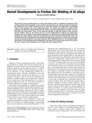
this method is shown schematically in Fig. 1 (Ref 1-16). This
joining technique is originally regarded to display similar solid-
state bonding conditions as the extrusion process (Ref 28, 29).
However, it was reported that the solid-state bonding conditions
are different in these processes. In extrusion, welding occurs
between two oxide-free surfaces and the determining parameter
is extrusion rate whereas the flowing material bonds on a
contaminated surface which is heated and compressed by the
action of the tool shoulder and the determining parameters are
tool rotational speed and traverse speed (Ref 29).
Generally, in friction stir butt-welding of thin plates a
cylindrical tool (a pin-type probe) is employed, whereas in butt-
welding of thicker plates a conical tool should be used. In both
cylindrical and conical tools, the tool surfaces are threaded. On
the other hand, lap-welding requires a modified tool to ensure
full disruption of the tenacious oxide layer present on the
surfaces of Al-alloys and a wider stir zone than butt-welding
(Ref 30, 31). Hence, more complex-shaped tools must be used
in lap-welding applications to break the stable oxide layers and
to obtain a better metallurgical bond, Fig. 2 (Ref 31). Various
friction stir welding tools have been developed and patented for
different applications. More information regarding the devel-
opments in stirring tool design can be found in excellent
reviews of Ma and Mishra (Ref 11), Nandan et al. (Ref 15),
Thomas et al. (Ref 31), and Rai et al. (Ref 32).
This welding process can be performed using special
friction stir welding equipments or a conventional vertical
milling machine. There exist different sizes of friction stir
welding devices manufactured for commercial purposes, cost-
ing as much as $1 million. Even though the method was
specifically developed for Al-alloys, it is also used successfully
for Al-Li alloys, 7075 Al-alloy and 0.8 mm thick zinc plates,
which are either difficult-to-weld or non-weldable through
conventional welding methods (Ref 11, 33-35). The method
also has potential for welding of Mg-, Cu-, Ti-, Al-alloy matrix
composites, lead, steels, stainless steels, thermoplastics, and
different materials with similar melting temperatures (welding
of Al-alloys with different Al-alloys and Al-alloys with Mg-
alloys). The state of art of friction stir welding of structural
alloys beyond Al-alloys has been discussed in detail in an
excellent recent review by C¸ am (Ref 36). Therefore, this issue
is out of the scope of this current work.
With this method, 50 mm thick Al-alloys plates can be butt-
welded and plates up to 100 mm thickness can also be butt-
joined by double-sided welding (Ref 11, 22-24, 37). The
double-sided friction stir welding application is shown sche-
matically in Fig. 3.
This welding method can also be used successfully in lap-
welding of plates. Moreover, the joining of plates with different
thickness can be achieved with this welding method by
plunging the tilted tool into the plates. Owing to the fact that
Fig. 1 Schematic presentation of friction stir welding technique
Fig. 2 Various friction stir welding pins: (a) a cylindrical pin used
in welding of thin plates, (b) a conical shape pin in welding of thick
plates and (c) TrifluteTM
type pin developed for friction stir overlap-
welding (Ref 31)
Fig. 3 Schematic illustration of double-sided friction stir welding
applied to thicker plates (Ref 22-24, 36)
Journal of Materials Engineering and Performance Volume 23(6) June 2014—1937
3. it is a mechanical solid state welding technique, it can also be
applied under water. The welding speed is dependent on the
thickness of the plate to be welded, typically 600 mm/min for
6 mm thick Al-alloy plates.
The advantages of friction stir welding over conventional
fusion welding processes are as follows (Ref 3, 11, 31, 33, 34):
• 2XXX and 7XXX series Al-alloys and Al-Li alloys,
which are difficult-to-weld through conventional welding
methods, can be successfully joined,
• The heat input during the welding is lower, therefore, the
loss in the mechanical properties is less,
• Shrinkage, distortion and residual stresses are very small
especially in thin plates,
• Surface preparation prior to welding is not too critical as
thin oxide films are tolerated,
• Because it is a solid state welding, problems encountered
in conventional fusion welding methods, such as cracking
and porosity formation are not experienced,
• There is no need for filler material,
• After the welding there is no need for further surface
treatment as it produces clean surfaces,
• Butt- and lap-welding are possible,
• Typically 1 km long welding can be achieved with the
same tool,
• It is environmentally friendly as there is no emission of
gas, dust or arc,
• It is highly energy-efficient,
• It is very suitable for automation and robotic applications.
The disadvantages are:
• It cannot be applied to every material. It can only be
applied to materials with low strength and low melting
point (higher melting point materials require special tools),
• The plates to be welded have to be fixed firmly,
• The speed of welding is relatively low (typically 750 mm/
min for 5 mm thick Al-alloy plates of 6XXX series),
• Powerful machines are needed for joining thicker plates.
Presently, this welding technique is commercially used in ship-
building (Ref 2, 3, 19),high-speedtrain manufacturing (Ref2, 19),
and aviation industry (Ref 2, 20, 21) as pointed out earlier.
Standard length Al-extrusion panels used in high speed cruises are
presently joined by this method, Fig. 4. Furthermore, this method
is successfully used in welding of fuel tanks of Al-Li 2195 alloy
space shuttles (Ref 21). Friction stir welding has a great potential
for light-weight Al-structures such as some parts in passenger
aeroplanes and further research is conducted in this field (Ref 19,
34). This welding technique is used in carriage manufacturing of
high speed trains in Japan, in the production of honeycomb
structures from Al extrusions (Fig. 5, 6) (Ref 19).
3. Process Parameters of Friction Stir Joining
General characteristics of FSW, namely weld variables, weld
defects encountered, plastic flow, microstructural evolution, and
Fig. 4 Friction stir joining of Al-extrusion panels used in high speed cruises (Ref 2, 3, 19)
Fig. 5 Friction stir joining of Al-panels in manufacturing of high speed trains in Japan (Ref 19)
1938—Volume 23(6) June 2014 Journal of Materials Engineering and Performance
4. grain refinement, are very briefly discussed in this section for
the sake of a better understanding. The readers may find more
detailed discussions on these issues in the following reviews
and books (Ref 11, 15, 16, 19, 20).
3.1 Weld Variables
The welding (traverse) speed, the tool rotational speed, the
vertical pressure on the tool (axial pressure), the tilt angle of the
tool, and the tool design are the main independent variables that
are used to control the FSW process (Ref 15). These variables
determine the peak temperature, x-direction force, torque, and
the power.
Peak temperature significantly increases with the increase in
tool rotational speed and decreases slightly with increasing
traverse speed. Figure 7 illustrates the effect of tool rotational
speed on the nugget formation at constant welding speed and
axial force (Ref 38). It also increases with increase in the axial
pressure. Axial pressure also influences the joint quality. Very
high pressures lead to overheating and thinning of the joint
while very low pressures may lead to insufficient heating and in
turn void formation. Higher traverse speeds may cause
excessive x-direction force, which may in turn lead to tool
erosion and, in extreme cases, tool breakage. Power require-
ment also increases with increasing axial pressure (Ref 15).
The torque depends on several parameters such as the
applied vertical pressure, tool design, the tilt angle, local shear
stress at the tool-workpiece interface, the friction coefficient
and the extend of slip between the tool and the workpiece. The
torque decreases with the increase in tool rotational speed
owing to the increase in peak temperature when other variables
are kept constant. On the other hand, torque is not significantly
affected by the change in traverse speed. The relative velocity
between the tool and the workpiece is mainly determined by the
tool rotational speed. Thus, the peak temperature is not
significantly affected by the traverse speed. High traverse
speeds tend to reduce heat input applied to the workpieces
during FSW. Therefore, the torque increases only slightly with
increasing traverse speed since material flow becomes some-
what more difficult at slightly lower temperatures (Ref 15).
3.2 Weld Defects
The joints obtained by friction stir welding usually exhibit a
better weld profile and surface quality than those obtained by
conventional fusion welding techniques. With this novel
method, defect-free joints are possible provided that the welding
is conducted properly and optimal welding parameters are used.
Surface irregularity, which is caused by unbalanced motion of
the tool, and kissing-bond type defects at the vicinity of the weld
root, that are encountered due to insufficient hydrostatic
pressure levels obtained during joining, are the characteristic
difficulties observed in this joining process (Ref 14). Another
surface defect encountered in FSW is in the form of excess flash,
caused by surface overheating as a result of significant
heterogeneity in heat generation at the interface between the
tool shoulder and the workpiece (Ref 39, 40).
Another possible welding flaw is the formation of a channel-
like void (wormhole defect) in the stir zone near the bottom of
the weld (Ref 14, 15). The flow of the plasticized material from
the stir zone beneath the shoulder may result in the formation of
this defect. This can be prevented by machining suitable
contours on the tool surface and under the tool shoulder, which
supports the material flow towards the bottom of the weld and
by keeping the depth of tool penetration constant throughout
the joining. It was found out that an increase in traverse speed,
at a constant rotational speed, leads to the formation of
wormhole defect near the bottom of the stirred zone (Ref 15,
39). Moreover, the size of the wormholes increases with the
travel speed (Ref 39) due to the inadequate material flow
towards the bottom of the weld. There are indications that the
ratio of travel speed to rotational speed is an important variable
Fig. 6 Schematic illustration of friction stir welding application in
the manufacturing of honeycomb structures (Ref 19)
Fig. 7 Macrographs showing the effect of tool rotation rate on the
nugget zone shape of friction stir welded AA2524-T351 (constant
welding speed and axial force). Note reduction in the size of nugget
zone with decreasing rotation rate (Ref 38)
Journal of Materials Engineering and Performance Volume 23(6) June 2014—1939
5. affecting the formation of the wormhole defect (Ref 15, 41, 42).
Long and Khanna (Ref 42) reported that a high travel-speed to
rotational-speed ratio for the same material and tool geometry
tends to favor the formation of these defects. It is also worth
pointing out that the propensity for voids or cracks generally
increases with the welding speed although there is an alloy-
dependence (Ref 39, 43).
It is obvious that tool design and welding variables affect
materials flow patterns. However, no relation between the
material flow and the formation of voids has yet been
established and no unified mechanism of void formation exists.
However, Elangovan and Balasubramanian (Ref 44) investi-
gated the effects of rotational speed and tool design on defect
formation in friction stir processing of AA2219. Five pin
profiles, namely straight cylindrical, tapered cylindrical,
threaded cylindrical, triangular and square, and were employed
to fabricate joints at various tool rotational speeds. It was found
out that the square tool pin profile resulted in the least defect
content in the weld as the flat faces produced a pulsating action
which led to more effective stirring. Moreover, a square tool
has higher eccentricity, which is defined as the ratio of the
dynamic volume swept by the tool to the static volume of the
tool. For instance, the eccentricity of a square tool is pd2
/4:d2
/
2 = p/2 = 1.57, where d is the diagonal of the square.
3.3 Microstructural Evolution
Typical microstructures observed in friction stir welded joint
are two types as schematically shown in Fig. 8 (Ref 36). In the
first type, the weld area consists of three distinct zones, namely
stirred (nugget) zone (also called dynamically recrystallized
zone, DXZ), thermo-mechanically affected zone (TMAZ) and
heat-affected zone (HAZ), as seen in Fig. 8(a) (Ref 11, 14, 15,
36, 45). This three-zone weld area is typically observed in
FSWed materials with low rates of recrystallization, such as Al-
alloys. However, the second type exhibits a weld cross-section
consisting of only two regions, namely stirred zone (also called
dynamically recrystallized zone) and HAZ, as shown in
Fig. 8(b). This type of microstructural evolution in the weld
area is usually observed in FSW of materials with a higher
rate of recrystallization, such as austenitic stainless steels and
Ti-alloys (Ref 36). Thus, there is no DXZ or TMAZ in this case
since both the entire DXZ and TMAZ regions are completely
recrystallized when the recrystallization is easily induced
(Ref 36).
The frictional heat and intense plastic deformation occurring
within the stirred zone result in dynamic recrystallization and
texture formation. The heat generated within the stirred zone is
determined by two factors, namely tool rotational speed and
traverse speed. The tool geometry plays an important role and
is the third factor affecting the heat generated within the stir
zone. Another important factor affecting the heat generated
within the stir zone is the thermal conductivity of the material-
to-be-welded. These factors, namely tool geometry, rotational
and traverse speeds, and thermal conductivity of the material,
also determine the shape of the stir zone (Ref 15). Furthermore,
parameters such as plate thickness and heat dissipation may
also influence the microstructural evolution in and around the
weld nugget.
The microstructural changes in various zones of a FSW joint
have significant effect on the joint performance. Therefore,
several investigations have been conducted on the microstruc-
tural changes within the stir zone of friction stir welds (Ref 4-7,
9, 10, 46-84). One has to balance the heat generated during
welding by optimizing the weld parameters, such as tool
rotational speed and traverse speed for a given tool geometry.
Low frictional heating results in undesirable material flow
leading to weld defects such as voids particularly in joining of
high melting point materials, whereas high frictional heating
leads to extensive growth of the recrystallized grains in and
around the stirred zone and dissolution of strengthening
precipitates in precipitation hardened materials such as high
strength Al-alloys.
Intense frictional heating and plastic deformation within the
stir zone leads to dynamic recrystallization resulting in fine-
grained microstructure unless excessive heat generated (Ref 6,
9, 11, 46-48, 64, 65). This region is referred to as stirred zone
(SZ) or dynamically recrystallized zone (DXZ). Under some
conditions, onion ring structure was observed within the stirred
zone (Ref 28). The formation of the onion rings is considered to
be due to the process of friction heating as a result of the
rotation of the tool and the forward movement extruding the
material around to the retreating side of the tool (Ref 28). The
spacing of the rings is found to be equal to the forward
movement of the tool in one rotation (Ref 28). The excessive
heat input to the material during joining due to very high
rotational speeds and/or large tool shoulder diameter and
surface area results in vanishing of the onion rings. The stirred
zone generally comprises the material most strongly affected by
the tool rotation. The peak temperatures in this region is
thought to be in the range of 0.6-0.95 Tm, depending on the
material, tool design and operating conditions (weld parame-
ters) (Ref 5, 52, 71-79). The upper portions of the stirred zone
experience heating and deformation effects from the tool
shoulder as well as from the tool pin. In the SZ, the material
undergoes dynamic recrystallization due to intense frictional
heat and plastic deformation as mentioned earlier.
Some researchers proposed on the other hand that the reason
for grain refinement within the SZ is extensive plastic
deformation and dynamic recovery, not the dynamic recrystal-
lization (Ref 72, 80). However, a mixture of recovery and
recrystallization phenomena occurs simultaneously (Ref 15).
Fig. 8 Schematical presentation illustrating the cross-sections of the
joint area obtained in friction stir welding: (a) in materials with
slower recrystallization rate (e.g., Al-alloys) and (b) in materials with
faster recrystallization rate (e.g., austenitic stainless steels or Ti-al-
loys). A: stirred zone (SZ), B: thermo-mechanically affected zone
(TMAZ), C: heat affected zone (HAZ)
1940—Volume 23(6) June 2014 Journal of Materials Engineering and Performance
6. The second region next to the SZ is the thermo-mechanically
affected zone (TMAZ), where the material experiences lesser
strains and strain rates as well as lower peak temperatures. This
region is often characterized by a pattern of grain distortion that
suggests shearing and flow of material about the rotating tool.
The grain distortion is believed to lead to fragmentation and
formation of fine equiaxed grains near the interface between
TMAZ and SZ (Ref 73). Next to the TMAZ, HAZ exists on
either side of the SZ, where the material experiences only a
thermal cycle.
3.4 Grain Refinement
Several investigations have well demonstrated that grain
refinement in the stir zones of Al-alloys (Ref 4-7, 9-11, 46-48,
51-97), carbon steels (Ref 98-106), and brasses (Ref 107-110)
is achieved in friction stir welding provided that the heat input
during welding is not excessively high. The reason for this is
the intense plastic deformation taking place within the stir zone
as pointed out earlier. Even ultra-fine grained microstructure
(average grain size <1 lm) can be achieved within stirred
zone by employing special tool geometries and external cooling
during welding (Ref 11, 47, 48, 51, 53-55, 70).
FSW parameters, namely tool rotational and traverse speeds,
tool geometry, vertical pressure applied, the heat generated,
materials properties such as thermal conductivity and external
cooling are the important factors influencing the grain size
evolving within the stirred zone. The degree of deformation is
the crucial factor determining the grain size of the recrystallized
grains (Ref 11). As the degree of deformation increases the
grain size decreases according to the general principles of
recrystallization. On the other hand, the heat input (energy
input per unit weld length) applied to the material during
welding results in grain coarsening. Increasing tool rotational
speed or ratio of tool rotational speed to traverse speed leads to
an increase both in the degree of deformation and the heat input
Fig. 9 The influence of tool rotation rate on the size of the recrystallized grains in the SZ of friction stir welded AA2524-T351 alloy with con-
stant welding speed and axial force. Note reduction in the grain size with decreasing rotation rate (Ref 38)
Journal of Materials Engineering and Performance Volume 23(6) June 2014—1941
7. (Ref 11, 81). Thus, the recrystallized grain size is determined
by the dominating factor between the tool rotational and
traverse speeds, in other words by the competition between the
degree of deformation and heat input. Several investigations
have well demonstrated that the grain size in the stirred zones
of Al-alloys can be reduced by decreasing the tool rotational
speed at a constant traverse speed or increasing weld speed at a
constant rotational speed or decreasing the ratio of tool
rotational speed to traverse speed (Fig. 9, 10, 11) (Ref 11, 35,
38, 50-54, 108, 109). Studies conducted on FSW of Al-alloys
have also revealed that the grain size varies within the stirred
zone, from the top to the bottom as well as from the weld
centerline to the sides (Ref 6, 11, 64). The variation of grain
size from the weld centerline to the edge of the stirred zone is
consistent with the temperature variation across the weld
nugget, being maximum at the centerline and decreasing with
distance on either side of it (Ref 6, 11). The grain size is also
found to decrease from the top to the bottom of weld nugget,
Fig. 10 Grain refinement in friction stir welds of 3 mm thick Cu-Zn30 and Cu-Zn37 alloys (i.e., 73/30 and 63/37 brasses): (a) macrograph
showing the cross-section of the joint, and microstructures of (b) base material (BM) and (c) stir zone (SZ) of 70/30 brass joint, and microstruc-
tures of the SZs of the 63/37 brass joints produced at a rotational rate of 1250 rpm with different traverse speeds: (d) 100 mm/min, (e) 125 mm/
min and (f) 150 mm/min. Note grain refinement in the SZ after FSW and reduction of grain size with increasing travel speed at a constant rota-
tion rate (Ref 36, 108, 109)
Fig. 11 The grain size in the weld nugget of FSWed AA2524 Al-
alloy joints as a function of rotation rate at constant weld speed and
vertical force (Ref 35)
1942—Volume 23(6) June 2014 Journal of Materials Engineering and Performance
8. which is believed to be due to temperature profile and heat
dissipation in the weld nugget (Ref 11). Since the bottoms of
the workpiece is in contact with the backing plate, the peak
temperature is lower and the thermal cycle is shorter compared
to the top region of the weld nugget, thus retarding the grain
coarsening and leading to finer grain sizes (Ref 11). In this
respect, the plate thickness is also an important factor
determining the grain size variation within the weld nugget.
4. Friction Stir Welding Of Al-Alloys
The technique has initially been widely investigated for
mostly low melting materials, such as Al, Mg, and Cu alloys. It
has proven to be very useful, particularly in the joining of the
difficult-to-fusion join high strength Al-alloys used in aero-
space applications, such as highly alloyed 2XXX and 7XXX
series aluminum alloys. The difficulty of making high-strength,
fatigue and fracture resistant welds in these aluminum alloys
has long inhibited the use of welding processes for joining
aerospace structures. Instead, mechanical fastening (e.g., rivet-
ing) has been the usually preferred joining method except in
production of pressure vessels for rocket propellant and
oxidizer tanks. Many of the problems with welds in aerospace
Al-alloys stem from the unfavorable distribution of brittle
solidification products, cracking and porosity in the weld
region. Encouraging results obtained in FSW of high-strength
aerospace aluminum alloys, that are typically difficult-to-weld,
have expanded the practical use of this technique. Friction stir
welding of Al-alloys will be discussed in two subsections,
namely FSW of non-heat-treatable alloys and of heat-treatable
(precipitation strengthened) alloys since the welding metallurgy
differs in these alloys significantly.
Al-alloys have a face-centered cubic crystal structure at all
temperatures up to their melting point. Thus, they do not
undergo an allotropic phase transformation. Al-alloys have low
density, about one third of steel or copper, and excellent
corrosion resistance. They are classified into two groups,
namely non-heat-treatable and heat-treatable alloys, depending
on their strengthening mechanism (Ref 111-113).
4.1 FSW of Non-heat-treatable Al-Alloys
4.1.1 Physical Metallurgy of Non-heat-treatable Al-
alloys. Non-heat-treatable Al-alloys are strengthened by solid
solution hardening (i.e., alloying) and cold-work hardening (by
cold rolling of plates at the last forming stage to certain levels)
mechanisms (Ref 113). Solid solution strengthened Al-alloys
exhibit the fewest problems with respect to the HAZ if they are not
cold-worked. They do not undergo a solid state transformation
and, therefore, the effect of the thermal cycle during welding is
small, and the properties of the HAZ are almost unaffected by the
welding. A slight grain coarsening in this region may take place
which does not usually alter the properties significantly. On the
other hand, the heat input applied to the material during fusion
welding may lead to the segregation and/or evaporation of solute
atoms in the FZ, which results in a loss of strength. The loss of
strength in the FZ of these alloys is negligible if the alloy is welded
in the annealed condition. The effect of the thermal cycle of fusion
welding is much more pronounced when the material is strain-
hardened.Inthis case, recrystallizationand graingrowth takeplace
in the HAZ as the temperature exceeds that of recrystallization
leading to a significant loss of strength, i.e., softening. The loss of
strength is particularly higher at regions near the FZ experiencing
higher temperatures where grain coarsening is more remarkable.
The FZ strength can, on the other hand, be increased by using
adequate filler wires in arc welding. Hence, the hardness minimum
lies within the HAZ next to the FZ. The strength of the fusion
welded joints of cold-worked alloys is generally lower than that of
the base material, which is another problem encountered in fusion
welding. The loss of strength in the weld region can be eliminated
by welding these alloys in annealed condition. Furthermore, the
strength loss in the fusion zone is much more pronounced in heat-
treatable Al-alloys (Ref 111-113).
Non-heat-treatable Al-alloys can readily be fusion-welded.
However, these alloys possess certain characteristics inherent to
all Al-alloys, such as a tenacious oxide layer, high thermal
conductivity, a high coefficient of thermal expansion, high
reflectivity, solidification shrinkage almost twice that of ferrous
alloys, relatively wide solidification temperature ranges, a
tendency to form low melting constituents, and high solubility
of hydrogen in molten state (Ref 111-113). Therefore, a
propensity for porosity formation may be encountered in fusion
welding of these alloys. Furthermore, the high reflectivity of
these alloys leads to difficulties in laser beam welding (Ref 113).
One of the difficulties encountered in fusion welding of non-
heat-treatable Al-alloys is the formation of porosity in fusion
zone as already mentioned. The porosity in aluminum alloys
weldments is mainly caused by hydrogen gas entrapped during
solidification, which has much higher solubility in liquid state
than solid state (Ref 111-113). In order to avoid the problem of
porosity formation, pre-weld joint preparation requires special
care. The surfaces should be thoroughly cleaned chemically or
mechanically prior to joining. Porosity formation is not a
concern in FSW due to its solid-state nature. Thus, surface
preparation is not critical in FSW of Al-alloys in contrast to
fusion welding.
Al-alloys are generally sensitive to weld metal cracking due
to their large solidification temperature range, high coefficient
of thermal expansion, and large solidification shrinkage. The
sensitivity of non-heat-treatable grades to cracking is lower
than that of the heat-treatable grades owing to the fact that they
are not as much heavily alloyed.
4.1.2 Weld Microstructure and Properties of Non-heat-
treatable Al-alloys. Generally, FSW does not lead to the loss
strength in the joint area in the solid-solution hardened
Al-alloys (Ref 114-117) since fine recrystallized grains are formed
in the SZ resulting in maintenance of the strength (Ref 3, 46,
51-54, 76, 86-97) (Tables 1, 2). Several studies (Ref 46, 76, 87-
97, 117, 118) have suggested that microstructural factors
govern the hardness within the joint area in FSW of the
solution-hardened Al-alloys. These studies have indicated that
the hardness is mainly determined by the grain size in friction
stir welds of solution hardened Al-alloys. Kwon et al. (Ref 51,
53, 54) adopted a cone-shaped pin with a sharpened tip to
reduce the amount of frictional heat generated during friction
stir processing (FSP) of Al 1050, hence to obtain ultra-fine
grains. A peak temperature of only 190 °C was recorded in the
FSP zone at a tool rotational speed of 560 rpm and a traverse
speed of 155 mm/min, which resulted in a grain size of 0.5 lm.
In an investigation on FSW of Al-alloy 5083-O, Svesson et al.
(Ref 117) proposed that the hardness profile depends mainly on
dislocation density, because the dominant hardening mecha-
nism for this alloy is strain hardening. However, a detailed
study more recently conducted on FSW of Al alloys 1080-O
Journal of Materials Engineering and Performance Volume 23(6) June 2014—1943
9. and 5083-O (Ref 115) has revealed that the factors governing
the hardness within the joint area is different in particle
containing and particle-free solution-hardened alloys although
the grain refinement occurs in both. For instance, a hardness
increase within the stirred zone was observed in the particle-
free Al-alloy 1080-O and the hardness can be explained by
Hall-Petch relation, indicating that the factor affecting the
hardness is grain size. On the other hand, it was observed that
the hardness could not be explained by the grain size in friction
stir welded Al-alloy 5083-O which contains a high density of
small particles. This study has suggested that the hardness
profiles are mainly governed by the particle distribution
(Orowan strengthening) in the friction stir welded Al alloy
containing many small particles (Ref 115). Attallah et al. (Ref
18) also proposed that the intermetallic particle distribution has
a greater effect on the onion ring formation than variations in
the processing parameters.
A recent work was conducted by Etter et al. (Ref 93) to
determine the effect of initial sheet microstructure on the
dynamic recrystallization mechanisms. For this purpose, Al
alloy 5251 sheets were friction stir welded in both cold-worked
(H14) and annealed (O) conditions. They proposed that the
recrystallization mechanisms are different in friction stir welded
cold-rolled (pre-strained) and annealed sheets, i.e., a continuous
dynamic recrystallization and a geometric dynamic recrystal-
lization, respectively.
It is also worth pointing out that the hardness profiles of
friction stir welded non-heat-treatable Al-alloys are also
governed by whether the material cold-rolled or annealed,
depending on the heat input during welding, as clearly
indicated in Fig. 12 (Ref 35). Generally, no loss of strength is
experienced; even higher strength levels can be obtained in the
weld zone as mentioned earlier when the material is annealed.
However, a hardness decrease may be observed in the stirred
zone of these alloys when welded in cold-rolled condition
unless the heat input is sufficiently low, due to the loss of cold-
work hardening (Table 2). For instance, a significant reduction
in hardness was reported in weld region of FSWed 5454-H32
alloy (Ref 35). Similarly, C¸ am et al. (Ref 94) observed a
Table 1 A summary of grain size in stirred zone of FSW non-heat-treatable Al-alloys
Material Thickness, mm Tool geometry Rotation rate, rpm Feed rate, mm/min Grain size, lm Ref.
AA 1050 5.0 Conical (no thread) 560 155 0.5 (Ref 51, 53, 54)
AA 1050 1.0 … … 400, 1320 <1 (Ref 88)
AA 1080-O 4.0 … … … 20 (Ref 115)
AA 1100 6.0 Cylindrical 400 60 4 (Ref 87)
AA 5052-O 2.0 Standard (a) 2000-4000 500-2000 3-16.1 (Ref 89)
AA 5083-Hxx 6.35 Standard 400 25.4-50.8 6.5-8.5 (Ref 11)
AA 5083-O 6.0 … … … 4 (Ref 115)
AA 5083-O 6.0-10.0 … … 46-132 10 (Ref 117)
AA 5083-H116 5.0 MX-Triflute 200 300 2-15 (Ref 18)
AA 5251-O 6.0 Standard 800 150 10 (Ref 76)
AA 5251-H34 5.0 MX-Triflute 500 500 2-10 (Ref 18)
AA 5754-Hxx 2.0 … … 100 6.4-13.5 (Ref 11)
AA 5754-O 2.3 Frustum-shaped 500 500 2-9 (Ref 18)
(a) Cylindrical threaded tool
Table 2 A summary of FSW joint efficiency values for non-heat-treatable Al-alloys
Material Thickness, mm Rm of BM, MPa Rm of FSW, MPa Joint efficiency, % Ref.
AA 1050-H24 5.0 117 85 73 (Ref 84)
AA 5005-H14 3.0 158 118 75 (Ref 13, 95)
AA 5083-O 5.0 309 300-320 97-104 (Ref 84)
AA 5083-O 6.0-15.0 285-298 271-344 95-119 (Ref 3, 11, 117)
AA 5083-O 3.0 285-298 316-334 95-119 (Ref 92)
AA 5086-H32 3.0 354 231-265 65-75 (Ref 94)
AA 5182-H111 1.0 275 278 101 (Ref 97)
AA 5754 1.0 230 $210 91 (Ref 118)
Fig. 12 Hardness distributions on transverse cross sections of fric-
tion stir welds in Al-alloy 5454 both in annealed, i.e., O (open
sysmbols) and cold worked conditions, i.e., H32 (closed sysmbols)
(Ref 35)
1944—Volume 23(6) June 2014 Journal of Materials Engineering and Performance
10. hardness decrease in the weld region of friction stir welded Al-
alloy 5086-H32, indicating that the heat input was high
resulting in loss of cold-work hardening and coarsening of
recrystallized grains within the SZ. The joint efficiency was
about 75%. Similar joint performance values were also reported
by von Strombeck et al. (Ref 13, 95), i.e., 75%, for friction stir
welded Al-alloy 5005-H14. The strength of FSWed cold
worked non-heat-treatable Al-alloys can somewhat increased
by increasing weld speed at a constant rotation rate. For
instance, Fig. 13 shows the variation of yield and tensile
strengths with increasing weld speed (Ref 35). On the other
hand, joint efficiencies between 95 and 120% were obtained in
friction stir welded Al-alloy 5083-O, indicating that the joints
perform as good as the base material when the alloy is welded
in annealed condition (Ref 3, 117).
4.2 FSW of Heat-treatable Al-Alloys
4.2.1 Physical Metallurgy of Heat-treatable Al-alloys.
A majority of the heat-treatable Al-alloys can be fusion-welded
readily. However, the propensity for porosity formation in fusion
joining is also the case in these alloys as in non-heat-treatable Al-
alloys. However, the porosity formation is not a concern in FSW
as it is a solid-state joining technique as mentioned earlier in FSW
of non-heat-treatable Al-alloys. The heat-treatable Al-alloys are
much more sensitive to weld metal cracking than non-heat-
treatable grades, as mentioned above (Ref 111-113). Weld
cracking in heat-treatable Al-alloys may be classified into two
groups, namely solidification cracking and liquation cracking.
Solidification cracking occurs within the fusion zone and is
caused by solidification shrinkage. Liquation cracking, on the
other hand, takes place in the HAZ next to the fusion zone and is
caused by the formation of low melting constituents as a result of
higher amount of alloying additions in these alloys. These
constituents have low melting points and so liquate (melt) during
welding, accompanied by tears provided that sufficient stress is
present (Ref 111-113, 119, 120). Higher heat input widens the
partially melted region and makes it more prone to tearing. Thus,
solidification cracking is not encountered in FSW, which is a
solid-state joining process. Moreover, liquation cracking is not an
usual problem in low-heat input FSW owing to its nature, as the
case in low heat input power beam welding (i.e., laser and
electron beam welding) (Ref 111, 112).
Heat-treatable Al-alloys differ from non-heat-treatable
Al-alloys in terms of strengthening mechanisms. These alloys
are capable of forming second-phase precipitates for improved
strength (Ref 15, 111-113). These alloys derive their strength
by virtue of precipitation hardening via natural or artificial
aging from the solution-treated condition. However, the HAZ
of these alloys undergoes an annealing cycle in the same
manner as work-hardened alloys. But, the microstructural
changes in this case are much more complex. The heat input
applied to the material during fusion welding also results in the
dissolution and coarsening of precipitates in the HAZ as well as
in the dissolution and segregation and/or evaporation of some
alloying elements in the FZ, i.e., base metal degradation,. The
maximum loss of strength is usually experienced in the HAZ
region of arc welds where overaging takes place resulting in
coarsening of precipitates as the strength of the FZ is
commonly increased via alloying by the use filler wires (Ref
111-113).
Most of the precipitation hardened Al-alloys can be fusion
welded, but the welds exhibit lower strength levels than those
of the base materials due to the fact that the thermal cycle of a
joining operation degrades the base material properties. The
extent of base metal degradation is determined by the welding
process and parameters (Ref 111-113, 121). Conventional arc-
welding processes involve the application of 103
-104
W/cm2
arc intensity and slow weld speeds (i.e., <15 mm/s) which
lead to excessive heat input into the base metal, thus resulting
in a coarse weld microstructure and a wide HAZ. The extent of
overaging, hence the loss of strength, in the HAZ region of the
low-heat input welds, such as autogenously laser beam (LB) or
electron beam (EB) welded joints, is not as high as that in arc
weldments (Ref 122-124). In these welds, the minimum
strength is usually observed in the FZ, where the dissolution
of precipitates takes place. Therefore, base metal degradation in
the HAZ (HAZ degradation) of heat-treatable Al-alloys is of
prime concern in arc welding. Generally, the loss of strength in
heat-treatable alloys is much more pronounced than that in non-
heat-treatable alloys (Ref 111-113).
As pointed out above, metallurgical transformations in the
weld region of heat-treatable alloys during fusion welding lead
to base metal degradation in this region. Post-weld solution
treating and aging provides the greatest improvement in joint
strength, but this practice involves use of water quenching
which may result in intolerable distortion in the workpiece.
Post-weld aging at lower temperatures provides, on the other
hand, moderate recovery of joint strength and does not require
water quenching (Ref 111, 112). An alternative way of
eliminating the loss of strength in the weld region is to weld
these alloys in solution-treated condition (T4) and age them
after welding (Ref 98). To accomplish this effectively, a
welding procedure that keeps the heat input relatively low and
short in duration, such as LB or EB welding, should be
employed (Ref 111, 112).
4.2.2 Weld Microstructure and Properties of Heat-treat-
able Al-alloys. FSW results in the temperature increase up to
400-550 °C within the nugget zone due to friction between the
tool and the workpiece and plastic deformation around the
rotating tool (Ref 5-7, 9, 11, 46, 51, 52, 56). At such a high
temperature, the base metal degradation, i.e., precipitate
dissolution and coarsening, occurs in and around the stir zone
(SZ) of friction stir welding of heat-treatable Al-alloys, leading
to loss of strength in the joint area (Ref 6, 11, 51, 56, 58, 65,
69). For instance, Liu et al. (Ref 46) examined microstructural
Fig. 13 Variation of transverse yield and tensile strengths of 5454-
H32 friction stir welds with the increase in weld speed at a constant
rotation rate (Ref 35)
Journal of Materials Engineering and Performance Volume 23(6) June 2014—1945
11. evolution in FSW Al 6061-T6 and reported that the homog-
enously distributed precipitates are generally smaller in the base
plate than in the joint area, implying the coarsening of the
precipitates. Similarly, Sato et al. (Ref 9) investigated the
microstructural evolution during FSW of Al 6063-T5 and they
could not observe any precipitates within the weld nugget in
TEM, indicating that all the precipitates dissolved (Ref 11).
Woo et al. (Ref 125) also reported that they did not observe any
precipitates within the weld nugget of friction stir processed Al
6061-T6 alloy plate indicating that they dissolved upon
welding thus leading to strength loss in weld region
(Fig. 14). More recently, Heinz and Skrotzki (Ref 58) also
reported complete dissolution of the precipitates in FSW Al
6013-T4 and T6. Su et al. (Ref 65) also observed that the
coarsening and coarsening/dissolution of the strengthening
precipitates take place in the HAZ and TMAZ of FSWAl 7075-
T651, respectively. Similarly, Jata et al. (Ref 69) also observed
the absence of the precipitates in the stir zone of FSW Al 7075-
T7451.
Grain refinement in the SZ also takes place in FSW of heat-
treatable Al-alloys (Ref 5, 7, 10, 11, 18, 47-49, 52, 55, 58, 61-
65, 67-70, 125-133), Table3. In order to obtain finer grains, thus
to achieve higher strength values within the SZ, external
cooling has been employed during welding (Ref 11, 47, 51, 53-
55). For instance, Benavides et al. (Ref 47) investigated the
effect of workpiece temperature on the grain size of FSW Al-
2024 and reported that the cooling the workpiece from 30 to
À30 °C with liquid nitrogen resulted in a decrease in the peak
temperature from 330 to 140 °C at a location 10 mm away
from the weld centerline, thereby leading to a reduction in the
grain size from 10 to 0.8 lm. Following a similar approach, Su
et al. (Ref 55) prepared bulk nanostructured Al7075 with an
average grain size of approx. 100 nm via FSP, using a mixture
of methanol and dry ice for cooling the plate rapidly behind the
tool. Similarly, Rhodes et al. (Ref 70) also produced a grain size
of about 25-100 nm within the SZ of friction stir processed
Al7050-T76 alloy by cooling the workpiece with a mixture of
dry ice and isopropyl alcohol.
However, the grain refinement cannot recover the loss of
strength due to precipitate dissolution and coarsening in these
high strength alloys and hence much lower joint efficiencies are
generally obtained (Table 4) (Ref 6, 11, 13, 49, 58, 67, 85, 95-
97, 126, 129-159). FSW does not lead to the loss of strength in
the joint area in these age-hardenable alloys if the welding is
conducted in annealed (i.e., O-treated) condition (Fig. 15, 16)
(Ref 144, 145, 147, 148), as it is the case in the solid-solution
hardened Al-alloys. On the other hand, as it is clearly seen from
Fig. 15 and 17, it leads to a softened zone in the joint area if the
alloy is friction stir welded in age-hardened condition (Ref 11,
15, 111, 112, 144, 145, 147, 148). Maximum joint efficiencies
of 75 and 80% were reported for FSWed Al6061-T6 and Al
7075-T6 alloys, respectively (Ref 144, 145). However, these
joint efficiency values were restored to about 90 and 100% by
subsequent artificial aging treatments (i.e., 6 h at 170 °C and
6 h at 140 °C, respectively) (Ref 147, 148). Similarly, Mahon-
ey et al. (Ref 6) investigated the joint efficiency of FSW Al
7075-T651 by transverse tensile testing at room temperature
and reported a joint efficiency of 75% for this alloy, indicating a
Fig. 14 TEM bright-field images of friction stir processed Al 6061-T6 alloy plate: (a) base material, (b) DXZ, (c) HAZ, and (d) TMAZ regions
(Ref 125)
1946—Volume 23(6) June 2014 Journal of Materials Engineering and Performance
12. significant loss of strength in the nugget zone, Table 4. They
also tried to improve the joint strength by applying a post-weld
aging (121 °C/24 h), which however further decreased the
strength, which is likely to be due to the high aging temperature
and long aging time used. Sato et al. (Ref 115) also investigated
the effect of post-weld heat treatments on the joint performance
of FSW Al 6063-T5. They observed that the post-weld aging
(175 °C/12 h) resulted in a slight recovery of the strength while
the post-weld solution heat treatment and aging (SHTA,
530 °C/1 h + 175 °C/12 h) increased the strength of the joint
to above that of the base plate with almost completely restored
ductility. Furthermore, the hardness and strength obtained in the
weld region of age-hardened alloys can somewhat increased by
increasing weld speed at constant rotation rate or increasing
rotation rate at constant weld speed as clearly shown in Fig. 18
and 19.
FSWed joints of age-hardened Al-alloys exhibit significant
strength loss in the weld region in the as-welded condition as
the case in fusion welding. It is thus proposed that it does not
offer any advantage over arc welding in joining of these alloys
with respect to the strength of the weld zone (Ref 15). The FZ
strength can be restored to some extent in arc welding by using
appropriate filler wires which is not possible in this solid state
welding method. However, the strength of HAZ cannot be
restored in fusion welding (Ref 111, 112). Moreover, the base
metal degradation in the FZ and HAZ of these alloys is not that
significant in low heat input welding methods, i.e., pulsed arc,
laser, or electron beam welding (Ref 15, 111, 112, 122-124,
160). It is, however, worth pointing out that the degree of
strength loss in friction stir welds of age-hardened alloys can be
minimized by using optimum weld parameters. In order to
increase the joint efficiency values of FSWed heat-treatable
alloys, higher traverse speeds at a constant ratio of rotational
speed to traverse speed can be used, which in turn reduces the
heat input applied to the workpieces. Moreover, the alloy can
be friction stir welded in the annealed condition, which is a
common approach to overcome the problem of strength loss
during arc welding welding (Ref 111, 112).
5. General Remarks
Most of FSW studies reported in the literature up to date
concentrated on FSW of Al-alloys, for which the method is
originally developed. As pointed out earlier, FSW does not
generally result in the loss strength in the joint area in the solid-
solution hardened Al-alloys provided that it is not heavily cold-
worked prior to joining. FSW only results in the formation of
recrystallized grains in the weld area of solid solution
strengthened Al-alloys due to the dynamic recrystallization,
provided that the plates are in the annealed condition prior to
joining. The size of recrystallized grains is determined by
welding conditions, hence by the heat input applied to the
workpiece during joining. If the alloy is in the cold-worked
condition, then there is a much more significant loss of strength
Table 3 A summary of grain size in stirred zone of FSW heat-treatable Al-alloys
Material Thickness, mm Tool geometry Rotation rate, rpm Feed rate, mm/min Grain size, lm Ref.
AA 2017-T6 3.0 Standard (a) 1250 60 9-10 (Ref 11)
AA 2024 6.35 Standard 200-300 25.4 2.0-3.9 (Ref 65)
AA 2024-T3 1.6, 4.0 … … … 5-10 (Ref 126)
AA 2024-T351 6.0 … … 80 2-3 (Ref 61)
AA 2024-T351 6.3 Frustum-shaped 468 75 2-7 (Ref 18)
AA 2024-T4 (b) 6.5 Standard 650 60 0.5-0.8 (Ref 45)
AA 2095 1.6 … 1000 126-252 1.6 (Ref 59)
AA 2219-T6 5.6 Standard 400-1200 100-800 8-15 (Ref 130)
AA 2519-T87 25.4 … 275 101.6 2-12 (Ref 11)
AA 6013-T4, T6 4.0 … 1400 400-450 10-15 (Ref 56)
AA 6013-T4 1.6, 4.0 … … … 15 (Ref 126)
AA 6061-T6 6.3 Standard 300-1000 90-150 10 (Ref 44)
AA 6063-T5 4.0 Standard 800-3600 180 5.9-17.8 (Ref 50)
AA 6082-T6 4.0 Standard 1600 40-460 2.0-2.8 (Ref 128)
AA 6082-T6 1.5 Non-threaded cylindrical 1810 460 2.8-3.9 (Ref 131)
AA 6181-T4 1.0, 2.0 Standard 1300-2000 800-1125 8.8-14.0 (Ref 129)
AA 7010-T7651 6.4 … 180, 450 95 1.7, 7.0 (Ref 62)
AA 7020-O 8.0 Standard 1120, 1400, 1800 20, 40, 80 1.0-9.0 (Ref 132)
AA 7039-T6 5.0 Standard 635 190 8.0 (Ref 133)
AA 7050-T7451 6.35 … 400 100 1-5 (Ref 67)
AA 7050-T651 6.35 … 350 15 1-4 (Ref 63)
AA 7075-T6 3.0 … 1500 300 3 (Ref 127)
AA 7075 (c) 2.0 … 1000 120 0.1 (Ref 53)
AA 7475 6.35 … … … 2.2 (Ref 66)
Al-Li-Cu 7.6 … … … 9 (Ref 10)
Cast Al-Cu-Mg-Ag-T6 4.0 … 850 75 3-5 (Ref 60)
Cast Al-Zn-Mg-Sc 6.7 Standard 400 25.4 0.68 (Ref 11)
(a) Cylindrical threaded tool
(b) Cooled with liquid nitrogen
(c) Cooled with water, methanol, dry ice
Journal of Materials Engineering and Performance Volume 23(6) June 2014—1947
13. both in the SZ and HAZ due to the heat input during joining,
which anneals and softens the material
The situation is much more complicated in FSW of heat-
treatable Al-alloys. A significant loss of strength takes place in
the weld area of these alloys after FSW, Table 4, both in the
HAZ and SZ. The loss of strength in the HAZ region is due to
the overaging in this region as a result of heat input. Overaging
also takes place in the HAZ of these alloys when they are
fusion welded, rendering this region the weakest location across
the joint Moreover, the degree of overaging is more pronounced
in fusion welding due to the higher heat inputs involved. This
difficulty is, however, inherent to precipitation hardened Al-
alloys and encountered in almost all welding processes.
Furthermore, the base metal degradation in FSW is not as high
as that in fusion welding processes involving higher heat inputs
provided that optimum welding conditions for relatively lower
peak temperatures are employed. That is why FSW has already
found remarkable industrial application for Al-alloys and its
industrial use is expected to increase.
Presently, friction stir welding (similar butt-, lap-, and spot-
welding applications in Al-alloys) is already used industrially in
manufacturing of ships, aeroplanes and space shuttles, trains,
and other vehicles. The applicability of FSW to join dissimilar
Al-alloys plates or Al-alloys plates with other materials (such as
Mg-alloys) is being currently investigated intensively. Thus, the
advancement achieved in this area (namely the progress made
in friction stir butt- and spot-welding of Al- and Mg-alloys,
particularly in dissimilar combinations) will make the mass
production of light transportation systems possible and hence
significant reduction in fuel consumption will be achieved. The
Table 4 A summary of FSW joint efficiency values for heat-treatable Al-alloys
Material Thickness, mm Rm of BM, MPa Rm of FSW, MPa Joint efficiency, % Ref.
AFC458-T8 … 545 362 66 (Ref 11)
AA 2014 8.0 459 344 75 (Ref 134)
AA 2014-T651 6.0 479-483 326-338 68-70 (Ref 11)
AA 2017-T351 5.0 428 351 82 (Ref 85)
AA 2024-T351 5.0 483-493 410-434 83-90 (Ref 11, 13, 95)
AA 2024-T3 3.0 457 402 88 (Ref 49)
AA 2024-T3 4.0 478 425-441 89-90 (Ref 11)
AA 2024-T3 1.6 417 369 89 (Ref 126)
AA 2024-T3 4.0 497 413 83 (Ref 126)
AA 2024-T8 3.0 476 397-453 83-95 (Ref 135)
AA 2195-T8 … 593 406.8 69 (Ref 11)
AA 2219-T87 … 475.8 310.3 65 (Ref 11)
AA 2219-O 5.0 159 159 100 (Ref 136)
AA 2219-T6 5.0 416 341 82 (Ref 136)
AA 2219-T6 5.0 416 295-329 80 (Ref 141)
AA 2519-T87 25.4 480 379 79 (Ref 11)
AA 6013-T4 1.6 346 252 73 (Ref 126)
AA 6013-T4 4.0 320 249 78 (Ref 126)
AA 6013-T4 4.0 320 300 94 (Ref 58)
AA 6013-T6 4.0 394 295 75 (Ref 58)
AA 6016-T4 1.0 226 185 82 (Ref 97)
AA 6056-T78 6.0 332 247 74 (Ref 96)
AA 6056-T4 4.0 316 180-280 57-88 (Ref 137)
AA 6056-T6 10.0 330 280 85 (Ref 138)
AA6060-T6 5.0 215 186 86 (Ref 143)
AA 6061-O 3.17 123 123 100 (Ref 144, 145)
AA 6061-T6 3.17 345 257 75 (Ref 144, 145)
AA 6061-T6 5.0 319-324 217-252 67-79 (Ref 11, 13, 95)
AA 6061-T6 3.0 342 231.6 64.2 (Ref 139)
AA 6063-T5 4.0 216 155 72 (Ref 115)
AA 6082-T6 3.0 322.9 221.3 68.5 (Ref 139)
AA 6082-T6 1.5 331 252 76 (Ref 140)
AA 6082-T6 1.5 331 252-254 76-77 (Ref 131)
AA 6181-T4 1.0, 2.0 274 249-258 91-94 (Ref 129)
AA 7020-O 8.0 251 251 100 (Ref 132)
AA 7020-T6 5.0 385 325 84 (Ref 13, 95)
AA 7020-T6 4.4 405 340 84 (Ref 146)
AA 7039-T6 5.0 414 354 86 (Ref 133)
AA 7050-T7451 6.4 545-558 427-441 77-81 (Ref 11, 67, 141)
AA 7075-O 3.17 216 216 100 (Ref 147, 148)
AA 7075-T6 3.17 580 474 82 (Ref 147, 148)
AA 7075-T6 5.0 485 373 77 (Ref 149)
AA 7075-T7351 … 472.3 455.1 96 (Ref 11)
AA 7075-T651 6.4 622 468 75 (Ref 6)
AA 7475-T76 … 505 465 92 (Ref 11)
1948—Volume 23(6) June 2014 Journal of Materials Engineering and Performance
14. application of this novel welding method will increase in the
coming days particularly in ship building, aeroplane and space
industry, automotive sector and other manufacturing sectors.
Similarly, industrial application of hybrid friction stir-laser
welding (laser-assisted friction stir welding) method is highly
possible in a near future.
Friction stir spot welding of Al-alloys plates led to the
design and manufacturing of vehicles using lighter materials
and, thus, is a candidate to replace steel bodies of cars
manufactured using resistance spot welding. Similarly, spot
Fig. 15 Hardness variations across transverse cross sections of fric-
tion stir welds produced in O- and T6-temper conditions: (a)
AA6061 and (b) AA7075 alloys (Ref 144, 145)
Fig. 16 Comparison of stress-elongation (in percent) curves of joints
produced in O-temper condition to those of the as-received O and T6
base plates: (a) AA6061 and (b) AA7075 alloy (Ref 147, 148)
Fig. 17 Comparison of stress-elongation (in percent) curves of
joints produced in T6-temper condition to those of the as-received
T6 base plate: (a) AA6061 and (b) AA7075 alloy (Ref 147, 148)
Fig. 18 Hardness in the weld nugget and HAZ of FSWed AA2524
Al-alloy joints as a function of rotation rate at constant weld speed
and vertical force (Ref 35)
Journal of Materials Engineering and Performance Volume 23(6) June 2014—1949
15. welding method is also candidate to replace riveting in bodies
of airplanes. Moreover, newly developed dual-rotation tech-
nique can significantly modify the velocity gradient between
the probe center and the shoulder diameter. Early trials confirm
that use of slower shoulder rotational speed lowers the HAZ
temperature during the welding operation. This effectively
reduces thermal softening in the HAZ region. This novel
welding (namely friction stir) technology has already changed
the design and manufacturing approaches in light transportation
systems and will continue to make an revolutionary impact in
manufacturing routes in the future.
References
1. W.M. Thomas, E.D. Nicholas, J.C. Needham, M.G. Murch, P.Temple-
Smith, and C.J. Dawes, International Patent Application No. PCT/
GB92/02203 and GB Patent Application No. 9125978.8 and US
Patent Application No. 5,460,317, Dec 1991
2. W.M. Thomas and E.D. Nicholas, Friction Stir Welding for the
Transportation _Industries, Mater. Des., 1997, 18, p 269–273
3. C.J. Dawes and W.M. Thomas, Friction Stir Process Welds Aluminum
Alloys, Weld. J., 1996, 75, p 41–45
4. W.B. Lee, Y.M. Yeon, and S.B. Jung, The _Improvement of
Mechanical Properties of Friction Stir Welded A356 Al Alloy, Mater.
Sci. Eng. A, 2003, 355A, p 154–159
5. C.G. Rhodes, M.W. Mahoney, W.H. Bingel, R.A. Spurling, and C.C.
Bampton, Effects of Friction Stir Welding on Microstructure of 7075
Aluminum, Scripta Mater., 1997, 36, p 69–75
6. M.W. Mahoney, C.G. Rhodes, J.G. Flintoff, R.A. Spurling, and W.H.
Bingel, Properties of Friction Stir Welded 7075 T651 Aluminum,
Metall. Mater. Trans. A, 1998, 29, p 1955–1964
7. L.E. Murr, G. Liu, and J.C. McClure, A TEM Study of Precipitation
and Related Microstructures in Friction-stir Welded 6061 Aluminum,
J. Mater. Sci., 1998, 33, p 1243–1251
8. O.V. Flores, C. Kennedy, L.E. Murr, D. Brown, S. Pappu, B.M.
Nowak, and J.C. McClure, Microstructural _Issues in a Friction-stir-
welded Aluminum Alloy, Scripta Mater., 1998, 38, p 703–708
9. Y.S. Sato, H. Kokawa, M. Enomoto, S. Jogan, and T. Hashimoto,
Precipitation Sequence in Friction Stir Weld of 6063 Aluminum
During Aging, Metall. Mater. Trans. A, 1991, 30, p 3125–3130
10. K.V. Jata and S.L. Semiatin, Continuous Dynamic Recrystallization
During Friction Stir Welding of High Strength Aluminum Alloys,
Scripta Mater., 2000, 43, p 743–749
11. R.S. Mishra and Z.Y. Ma, Friction Stir Welding and Processing,
Mater. Sci. Eng. R, 2005, 50, p 1–78
12. G. C¸ am and M. Koc¸ak, Joining of Advanced Materials, Area 6:
Materials Science and Engineering, Topic 6.36.4: Materials Processing
and Manufacturing Technologies, Encyclopedia of Life Support
Systems (EOLSS), Developed under the auspices of the UNESCO,
R.D. Rawlings, Ed., Eolss Publishers, Oxford, UK (online), 2002-2014.
http://www.eolss.net/
13. A. von Strombeck, G. C¸ am, J.F. dos Santos, V. Ventzke, and M.
Koc¸ak, A Comparison Between Microstructure, Properties, and
Toughness Behavior of Power Beam and Friction Stir Welds in Al-
alloys, Proc. of the TMS 2001 Annual Meeting Aluminum, Automotive
and Joining, S.K. Das, J.G. Kaufman, and T.J. Lienert, Eds., Feb 12-
14, 2001 (New Orleans, Louisiana, USA), TMS, Warrendale, PA,
USA, 2001, p 249-264
14. P.L. Threadgill, A.J. Leonard, H.R. Shercliff, and P.J. Withers,
Friction Stir Welding of Aluminium Alloys, Int. Mater. Rev., 2009, 54,
p 49–93
15. R. Nandan, T. DebRoy, and H.K.D.H. Bhadeshia, Recent Advances in
Friction Stir Welding-Process, Weldment Structure and Properties,
Prog. Mater. Sci., 2008, 53, p 980–1023
16. G. Campbell and T. Stotler, Friction Stir Welding of Armor Grade
Aluminum Plate, Weld. J., 1999, 78, p 45–47
17. P.L. Threadgill, Terminology in Friction Stirwelding, Sci. Technol.
Weld. Join., 2007, 12, p 357–360
18. M.M. Attallah, C.L. Davies, and M. Strangwood, Influence of Base
Metal Microstructure on Microstructural Development in Aluminium
Based Alloy Friction Stir Welds, Sci. Technol. Weld. Join., 2007, 12,
p 361–369
19. S.W. Kallee, J. Davenport, and E.D. Nicholas, Railway Manufacturers
implement friction Stir Welding, Weld. J., 2002, 81, p 47–50
20. M.R. Johnsen, Friction Stir Welding Takes off at Boeing, Weld. J.,
1999, 78, p 35–39
21. J. Ding, R. Carter, K. Lawless, A. Nunes, C. Russel, M. Suits, and J.
Schneider, Friction Stir Welding Flies High at NASA, Weld. J., 2006,
85, p 54–59
22. D.G. Staines, W.M. Thomas, S.W. Kallee, and P.J. Oakley, Friction
Stir Technology—Recent Developments in Process Variants and
Applications, COM 2006, Oct 1-4 2006
23. W.M. Thomas, Friction Stir Welding and Related Friction Process
Characteristics, INALCO 98 7th International Conference, Joints in
Aluminium, Cambridge, UK, 1998
24. W.M. Thomas, E.D. Nicholas, E.R. Watts, and D.G. Staines, Friction
Based Welding Technology for Aluminium, The 8th International
Conference on Aluminium Alloys, 2-5 July 2002, Cambridge, UK, 2002
25. Kawasaki Heavy Industries, Ltd., A New Method for Light Alloy
Joining—Friction Spot Joining, 2006-2014. www.kawasakirobot.com
27. G. Kohn, Y. Greenberg, I. Makover, and A. Munitz, Laser-assisted
Friction Stirwelding, Weld. J., 2002, 81, p 46–48
28. K.N. Krishnan, On the Formation of Onion Rings in Friction Stir
Welds, Mater. Sci. Eng. A, 2002, 327, p 246–251
29. G. Buffa, L. Donati, L. Fratini, and L. Tomesani, Solid State Bonding
in Extrusion and FSW: Process Mechanics and Analogies, J. Mater.
Process. Technol., 2006, 177, p 344–347
30. G.M.D. Cantin, S.A. David, W.M. Thomas, E. Lara-Curzio, and S.S.
Babu, Friction Skew-Stir Welding of lap Joints in 5083-O Aluminum,
Sci. Technol. Weld. Join., 2005, 10, p 268–280
31. W.M. Thomas, K.I. Johnson, and C.S. Wiesner, Friction Stir
Welding—Recent Developments in Tool and Process Technologies,
Adv. Eng. Mater., 2003, 5, p 485–490
32. R. Rai, A. De, H.K.D.H. Bhadeshia, and T. DebRoy, Review: Friction
Stir Welding Tools, Sci. Technol. Weld. Join., 2011, 16, p 325–342
33. J. Defalco, Friction Stir Welding vs. Fusion Welding, Weld. J., 2006,
85, p 42–44
34. J.W. Arbegast, Friction Stir Welding, Weld. J., 2006, 85, p 28–35
35. R.S. Mishra and M.W. Mahoney, Eds., Friction Stir Welding and
Processing, ASM International, Materials Park, Ohio, USA, 2007
36. G. C¸ am, Friction Stir Welded Structural Materials Beyond Al-alloys,
Int. Mater. Rev., 2011, 56, p 1–48
37. E. Dalder, J.W. Pastrnak, J. Engel, R.S. Forrest, E. Kokko, K.
McTernan, and D. Waldron, Bobbin-Tool Friction—Stir Welding of
Thick-Walled Aluminum Alloy Pressure Vessels, Weld. J., 2008, 87,
p 40–44
38. J. Yan, M.A. Sutton, and A.P. Reynolds, Process-Structure-Property
Relationships for Nugget and HAZ Regions of AA2524-T351
Friction Stir Welds, Sci. Technol. Weld. Join., 2005, 10, p 725–736
Fig. 19 Hardness in the weld nugget of FSWed AA7050 Al-alloy
joints as a function of weld speed at constant rotation rate and verti-
cal force (Ref 35)
1950—Volume 23(6) June 2014 Journal of Materials Engineering and Performance
16. 39. R. Crawford, G.E. Cook, A.M. Strauss, D.A. Hartman, and M.A.
Stremler, Experimental Defect Analysis and Force Prediction Simu-
lation of High Weld Pitch Friction Stir Welding, Sci. Technol. Weld.
Join., 2006, 11, p 657–665
40. Y.G. Kim, H. Fujii, T. Tsumura, T. Komazaki, and K. Nakata, Three
Defect Types in Friction Stir Welding of Aluminum die Casting Alloy,
Mater. Sci. Eng. A, 2006, 415, p 250–254
41. H.J. Liu, H. Fujii, M. Maeda, and K. Nogi, Tensile Properties and
Fracture Locations of Friction-Stir Welded Joints of 6061-T6
Aluminium Alloy, J. Mater. Sci. Technol., 2004, 20, p 103–105
42. X. Long and S.K. Khanna, Modelling of Electrically Enhanced
Friction Stir Welding Process Using Finite Element Method, Sci.
Technol. Weld. Join., 2005, 10, p 482–487
43. R. Leal and A. Loureiro, Defects Formation in Friction Stir Welding
of Aluminium, Mater. Sci Forum, 2004, 455-456, p 299–302
44. K. Elangovan and V. Balasubramanian, Influences of Pin Profile and
Rotational Speed of the Tool on the Formation of Friction Stir
Processing Zone in AA2219 Aluminium Alloy, Mater. Sci. Eng. A,
2007, 459, p 7–18
45. Dong et al., Characteristics and mechanism on the distortion of
friction stir welded aluminium alloy sheet. Proc. of the 1st Int. Symp.
on Friction Stir Welding, 14-16 June 1999, Thousand Oaks, CA,
USA, 1999
46. G. Liu, L.E. Murr, C.-S. Niou, J.C. McClure, and F.R. Vega,
Microstructural Aspects of the Friction-Stir Welding of 6061-T6
Aluminum, Scripta Mater., 1997, 37, p 355–361
47. S. Benavides, Y. Li, L.E. Murr, D. Brown, and J.C. McClure, Low
Temperature Friction Stir Welding of 2024 Aluminum, Scripta Mater.,
1999, 41, p 809–815
48. Z.Y. Ma, R.S. Mishra, and M.W. Mahoney, Superplastic Deformation
Behaviour of Friction Stir Processed 7075Al Alloy, Acta Mater.,
2002, 50, p 4419–4430
49. S.A. Khodir, T. Shibayanagi, and M. Naka, Microstructure and
Mechanical Properties of Friction Stir Welded AA2024-T3 Aluminum
Alloy, Mater. Trans., 2006, 47, p 185–193
50. S.R. Ren, Z.Y. Ma, and L.Q. Chen, Effect of Welding Parameters on
Tensile Properties and Fracture Behavior of Friction Stir Welded Al-
Mg-Si Alloy, Scripta Mater., 2007, 56, p 69–72
51. Y.J. Kwon, N. Saito, and I. Shigematsu, Friction Stir Process as a New
Manufacturing Technique of Ultrafine-Grained Aluminum Alloy, J.
Mater. Sci. Lett., 2002, 21, p 1473–1476
52. Y.S. Sato, M. Urata, and H. Kokowa, Parameters Controlling
Microstructure and Hardness During Friction-Stir Welding of Precip-
itation-Hardenable Aluminium Alloy 6063, Metall. Mater. Trans. A,
2002, 33, p 625–635
53. Y.J. Kwon, I. Shigematsu, and N. Saito, Production of Ultra-Fine
Grained Aluminum Alloy Using Friction Stir Process, Mater. Trans.,
2003, 44, p 1343–1350
54. Y.J. Kwon, I. Shigematsu, and N. Saito, Mechanical Properties of
Fine-Grained Aluminum Alloy Produced by Friction Stir Process,
Scripta Mater., 2003, 49, p 785–789
55. J.Q. Su, T.W. Nelson, and C.J. Sterling, Microstructure Evolution
During FSW/FSP of High Strength Aluminum Alloys, Mater. Sci.
Eng. A, 2005, 405, p 277–286
56. W. Tang, X. Guo, J.C. McClure, and L.E. Murr, Heat _Input and
Temperature Distribution in Friction Stir Welding, J. Mater. Process.
Manuf. Sci., 1998, 7, p 163–172
57. A.P. Reynolds, Visualisation of Material Flow in Autogenous Friction
Stirwelds, Sci. Technol. Weld. Join., 2000, 5, p 120–124
58. B. Heinz and B. Skrotzki, Characterization of a Friction Stir Welded
Aluminum Alloy 6013, Metall. Mater. Trans. B, 2002, 33, p 489–498
59. G.S. Frankel and Z. Xia, Localized Corrosion and Stress Corrosion
Cracking Resistance of Friction Stir Welded Aluminum Alloy 5454,
Corrosion, 1999, 55, p 139–150
60. Y.S. Sato, H. Kokowa, K. Ikeda, M. Enomoto, S. Jogan, and T.
Hashimoto, Microtexture in the Friction-Stir Weld of an Aluminum
Alloy, Metall. Mater. Trans. A, 2001, 32, p 941–948
61. H.G. Salem, A.P. Reynolds, and J.S. Lyons, Microstructure and
Retention of Superplasticity of Friction Stir Welded Superplastic 2095
Sheet, Scripta Mater., 2002, 46, p 337–342
62. L. Litynska, R. Braun, G. Staniek, C. Dalle Donne, and J. Dutkiewicz,
TEM Study of Themicrostructure Evolution in a Friction Stir-Welded
Al Cu Mg Ag alloy, Mater. Chem. Phys, 2003, 81, p 293–295
63. A.F. Norman, I. Brough, and P.B. Prangnell, High Resolution EBSD
Analysis of the Grain Structure in a AA2024 Friction Stir Weld,
Mater. Sci. Forum, 2000, 331-337, p 1713–1718
64. K.A.A. Hassan, A.F. Norman, D.A. Price, and P.B. Prangnell,
Stability of Nugget Zone Grain Structures in High Strength Al Alloy
Friction Stir Welds During Solution Treatment, Acta Mater., 2003, 51,
p 1923–1936
65. J.Q. Su, T.W. Nelson, R.S. Mishra, and M.W. Mahoney, Microstruc-
tural _Investigation of Friction Stir Welded 7050-T651 Aluminum,
Acta Mater., 2003, 51, p 713–729
66. Z.Y. Ma, R.S. Mishra, M.W. Mahoney, and R. Grimes, High Strain
Rate Superplasticity in Friction Stir Processed Al-Mg-Zr Alloy,
Mater. Sci. Eng. A, 2003, 351, p 148–153
67. I. Charit and R.S. Mishra, High Strain Rate Superplasticity in a
Commercial 2024 Al Alloy via Friction Stir Processing, Mater. Sci.
Eng. A, 2003, 359, p 290–296
68. I. Charit, R.S. Mishra, and M.W. Mahoney, Multi-sheet Structures in
7475 Aluminum by Friction Stir Welding in Concert With Post-weld
Superplastic Forming, Scripta Mater., 2002, 47, p 631–636
69. K.V. Jata, K.K. Sankaran, and J.J. Ruschau, Friction Stir Welding
Effects on Microstructure and Fatigue of Aluminum Alloy 7075-
T7451, Metall. Mater. Trans. A, 2000, 31, p 2181–2192
70. C.G. Rhodes, M.W. Mahoney, W.H. Bingel, and M. Calabrese, Fine-
grain Evolution in Friction Stir Processed 7075 Aluminum, Scripta
Mater., 2003, 48, p 1451–1455
71. K. Oh-Ishi and T.R. McNelley, Microstructural Modification of As-
cast NiAl Bronze by Friction Stir Processing, Metall. Mater. Trans. A,
2004, 35, p 2951–2961
72. R.W. Fonda, J.F. Bingert, and K.J. Colligan, Development of Grain
Structure During Friction Stir Welding, Scripta Mater., 2004, 51, p
243–248
73. T.R. McNelley, S. Swaminathan, and J.Q. Su, Recrystallization
Mechanisms During Friction Stir Welding/Processing of Aluminum
Alloys, Scripta Mater., 2008, 58, p 349–354
74. Z.Y. Ma, S.R. Sharma, and R.S. Mishra, Effect of Friction Stir
Processing on the Microstructure of Cast A356 Aluminum, Mater.
Sci. Eng. A, 2006, 433, p 269–278
75. K. Kumar and S.V. Kailas, The Role of Friction Stir Welding and
Material Flow and Weld Formation, Mater. Sci. Eng. A, 2008, 485, p
367–374
76. H. Jin, S. Saimoto, M. Ball, and P.L. Threadgill, Characterisation of
Microstructure and Texture in Friction Stir Welded Joints of 5754 and
5182 Aluminium Alloy Sheets, Mater. Sci. Technol., 2001, 17, p
1605–1614
77. D.P. Field, T.W. Nelson, Y. Hovanski, and K.V. Jata, Heterogeneity of
Crystallographic Texture in Friction Stir Welds of Aluminum, Metall.
Mater. Trans. A, 2001, 32, p 2869–2877
78. H.N.B. Schmidt, T.L. Dickerson, and J.H. Hattel, Material Flow in
Butt Friction Stir Welds in AA2024-T3, Acta Mater., 2006, 54(4), p
1199–1209
79. R.S. Mishra and M.W. Mahoney, Friction Stir Processing: A new
Grain Refinement Technique to Achieve High Strain Rate Super-
plasticity in Commercial Alloys, Mat. Sci. Forum, 2001, 357,
p 507–514
80. M.R. Barnett and F. Montheillet, The Generation of new High-Angle
Boundaries in aluminum During Hot Torsion, Acta Mater., 2002, 50,
p 2285–2296
81. P.A. Colegrove and H.R. Shercliff, Experimental and Numerical
Analysis of Aluminum Alloy 7075-T7351 Friction Stir Welds, Sci.
Technol. Weld. Join., 2003, 8, p 360–368
82. H.J. Liu, H. Fujii, and K. Nogi, Microstructure and Mechanical
Properties of Friction Stir Welded Joints of AC4A Cast Aluminium
Alloy, Mater. Sci. Techol., 2004, 20, p 399–402
83. H. Fujii, Y.G. Kim, T. Tsumura, T. Komazaki, and K. Nakata,
Estimation of Material Flow in Stir Zone During Friction Stir Welding
by Distribution Measurement of Si Particles, Mater. Trans., 2006, 47,
p 224–232
84. H. Fujii, L. Cui, M. Maeda, and K. Nogi, Effect of Tool Shape on
Mechanical Properties and Microstructure of Friction Stir Welded
Aluminium Alloys, Mater. Sci. Eng. A, 2006, 419, p 25–31
85. H.J. Liu, H. Fujii, M. Maeda, and K. Nogi, Tensile Properties and
Fracture Locations of Friction-Stir-Welded Joints of 2017-T351
Aluminum Alloy, J. Mater. Process. Technol., 2003, 142, p 692–696
Journal of Materials Engineering and Performance Volume 23(6) June 2014—1951
17. 86. Y.S. Sato, Y. Kurihara, S.H.C. Park, H. Kokowa, and N. Tsuji,
Friction Stir Welding of Ultrafine Grained Al Alloy 1100 Produced by
Accumulative Roll-Bonding, Scripta Mater., 2004, 50, p 57–60
87. L.E. Murr, G. Liu, and J.C. McClure, Dynamic Recrystallization in
Friction-Stir Welding of Aluminum Alloy 1100, J. Mater. Sci. Lett.,
1997, 16, p 1801–1803
88. Y.S. Sato, M. Urata, H. Kokowa, K. Ikeda, and M. Enomoto,
Retention of Fine Grained Microstructure of Equal Channel Angular
Pressed Al Alloy 1050 by Friction Stir Welding, Scripta Mater., 1050,
45(2001), p 109–114
89. M. Peel, A. Steuwer, M. Preuss, and P.J. Withers, Microstructure,
Mechanical Properties and Residual Stresses as a Function of Welding
Speed in Aluminium AA5083 Friction Stir Welds, Acta Mater., 2003,
51, p 4791–4801
90. C. Genevois, A. Deschamps, and P. Vacher, Comparative Study on
Local and Global Mechanical Properties of 2024 T351, 2024 T6 and
5251 O Friction Stir Welds, Mater. Sci. Eng. A, 2006, 415, p 162–170
91. Y.S. Sato, M. Urata, H. Kokowa, and K. Ikeda, Hall-Petch
Relationship in Friction Stir Welds of Equal Channel Angular Pressed
Aluminium Alloys, Mater. Sci. Eng. A, 2003, 354, p 298–305
92. T. Hirata, T. Oguri, H. Hagino, T. Tanaka, S.W. Chung, Y. Takigawa,
and K. Higashi, Influence Offriction Stir Welding Parameters on
Grain Size and Formability in 5083 Aluminum Alloy, Mater. Sci. Eng.
A, 2007, 456, p 344–349
93. A.L. Etter, T. Baudin, N. Fredj, and R. Penelle, Recrystallization
Mechanisms in 5251 H14 and 5251 O Aluminum Friction Stir Welds,
Mater. Sci. Eng. A, 2007, 445-446, p 94–99
94. G. C¸ am, S. Gu¨c¸lu¨er, A. C¸ akan, and H.T. Serindag˘, Mechanical
Properties of Friction Stir Butt-Welded Al-5086 H32 Plate, Mat.-wiss.
u. Werkstofftech., 2009, 40, p 638–642
95. A. von Strombeck, J.F. dos Santos, F. Torster, P. Laureano, and M.
Koc¸ak, Fracture Toughness Behavior of FSW Joints on Aluminum
Alloys, Proc. 1st Int. Symp. on Friction Stir Welding, Thousand Oaks,
CA, USA, June 14-16, 1999
96. A. Denquin, D. Allehaux, M.H. Campagnac, and G. Lapasset,
Microstructural and Mechanical Evolutions Within Friction Stir
Welds of Precipitation Hardened Aluminium Alloys, Mater. Sci.
Forum, 2003, 426-432, p 2921–2926
97. C. Leitao, R.M. Leal, D.M. Rodrigues, A. Loureiro, and P. Vilac¸a,
Mechanical Behaviour of Similar and Dissimilar AA 5182-H111and AA
6016-T4 Thin Friction Stir Welds, Mater. Des., 2009, 30, p 101–108
98. W.M. Thomas, P.L. Threadgill, and E.D. Nicholas, Feasibility of
Friction Stir Welding Steel, Sci. Technol. Weld. Join., 1999, 4, p 365–
372
99. T.J. Lienert, W.L. Stellwag, B.B. Grimmett, and R.W. Warke, Friction
Stir Welding Studies on Mild Steel—Process Results, Microstructures,
and Mechanical Properties are Reported, Weld. J., 2003, 82, p 1s–9s
100. A.P. Reynolds, W. Tang, M. Posada, and J. DeLoach, Friction Stir
Welding of DH36 Steel, Sci. Technol. Weld. Join., 2003, 8, p 455–460
101. P.J. Konkol, C.J.A. Mathers, R. Johnson, and J.R. Pickens, Friction
Stir Welding of HSLA-65 Steel for Ship Building, J. Ship Prod.,
2003, 19, p 159–164
102. A. Ozekcin, H.W. Jin, J.Y. Koo, N.V. Bangaru, R. Ayer, G. Vaughn,
R. Steel, and S. Packer, A Microstructural Study of Friction Stir
Welded Joints of Carbon Steels, Int. J. Offshore Polar Eng., 2004, 14,
p 284–288
103. R. Ueji, H. Fujii, L. Cui, A. Nishioka, K. Kunishige, and K. Nogi,
Friction Stir Welding of Ultrafine Grained Plain Low-Carbon Steel
Formed by the Martensite Process, Mater. Sci. Eng. A, 2006, 423, p
324–330
104. H. Fujii, R. Ueji, Y. Takada, H. Kitahara, N. Tsuji, K. Nakata, and K.
Nogi, Friction Stir Welding of Ultrafine Grained _Interstitial Free
Steels, Mater. Trans., 2006, 47, p 239–242
105. H. Fujii, L. Cui, N. Tsuji, M. Maeda, K. Nakata, and K. Nogi, Friction
Stir Welding of Carbon Steel, Mater. Sci. Eng. A, 2006, 429, p 50–57
106. L. Cui, H. Fujii, N. Tsuji, and K. Nogi, Friction Stir Welding of a
High Carbon Steel, Scripta Mater., 2007, 56, p 637–640
107. H.S. Park, T. Kimura, T. Murakami, Y. Nagano, K. Nakata, and M.
Ushio, Microstructure and Mechanical Properties of Friction Stir
Welds of 60% Cu-40% Zn Copper Alloy, Mater. Sci. Eng. A, 2004,
371, p 160–169
108. G. C¸ am, H.T. Serindag, A. C¸ akan, S. Mistikoglu, and H. Yavuz, The
Effect of Weld Parameters on Friction Stir Welding of Brass Plates,
Mat.-wiss. u. Werkstofftech., 2008, 39, p 394–399
109. G. C¸ am, S. Mistikoglu, and M. Pakdil, Microstructural and Mechan-
ical Characterization of Friction Stir Butt Joint Welded 63%Cu-
37%Zn Brass Plate, Weld. J., 2009, 88, p 225s–232s
110. W.B. Lee and S.B. Jung, The Joint Properties of Copper by Friction
Stir Welding, Mater. Lett., 2004, 58, p 1041–1046
111. G. C¸ am and M. Koc¸ak, Progress in Joining of Advanced Materials,
Int. Mater. Rev., 1998, 43, p 1–44
112. G. C¸ am and M. Koc¸ak, Progress in Joining of Advanced Materi-
als—Part II: Joining of Metal Matrix Composites and Joining of Other
Advanced Materials, Sci. Technol. Weld. Join., 1998, 3, p 159–175
113. ASM International, Welding, Brazing and Soldering, ASM Handbook,
D.L. Olson et al., Ed., ASM International, Materials Park, 1993,
114. A.P. Reynolds, Mechanical and Corrosion Performance of TGA and
Friction Stir Welded Aluminum for Tailor Welded Blanks: Alloys
5454 and 6061, Proc. 5th Int. Conf. on Trends in Welding Research,
J.M. Vitek et al., Eds., 1-5 June, 1998 (Pine Mountain, GA), ASM
International, Materials Park, OH, 1999, p 563-567
115. Y.S. Sato, S.H.C. Park, and H. Kokowa, Microstructural Factors
Governing Hardness in Friction-Stir Welds of Solid-Solution-Hard-
ened Al Alloy, Metall. Mater. Trans. A, 2001, 32, p 3033–3042
116. M. Kumagai and S. Tanaka, Application of Friction Stir Welding to
Welded Construction of Aluminum Alloys, J. Light Met. Weld.
Constr., 2001, 39, p 22–28
117. L.-E. Svensson, L. Karlsson, H. Larsson, B. Karlsson, M. Fazzini, and
J. Karlsson, Microstructure and Mechanical Properties of Friction Stir
Welded Aluminium Alloys with Special Reference to AA 5083 and
AA 6082, Sci. Technol. Weld. Join., 2000, 5, p 285–296
118. M. Simoncini and A. Forcellese, Effect of the Welding Parameters and
Tool Configuration on Micro- and Macro-mechanical Properties of
Similar and Dissimilar FSWed Joints in AA5754 and AZ31 Thin
Sheets, Mater. Des., 2012, 41, p 50–60
119. P.B. Dickerson and B. Irving, Welding Aluminium: ItÕs not as
Difficult as it Sounds, Weld. J., 1992, 71, p 45–50
120. S. Kou, Welding Metallurgy, Wiley, New York, 1987, p 239
121. R.J. Brungraber and F.G. Nelson, Effect of Welding Variables on
Aluminum Alloy Weldments, Weld. J., 1973, 52, p 97s–103s
122. G. C¸ am, V. Ventzke, J.F. dos Santos, M. Koc¸ak, G. Jennequin, and P.
Gonthier-Maurin, Characterisation of Electron Beam Welded Alu-
minium Alloys, Sci. Technol. Weld. Join., 1999, 4, p 317–323
123. G. C¸ am, V. Ventzke, J.F. dos Santos, M. Koc¸ak, G. Jennequin, P. Gonthier-
Maurin, M. Penasa, and C. Rivezla, Characterization of Laser and Electron
Beam Welded Al Alloys, Pract. Metallogr., 2000, 37, p 59–89
124. G. C¸ am and M. Koc¸ak, Microstructural and Mechanical Character-
ization of Electron Beam Welded Al-alloy 7020, J. Mater. Sci., 2007,
42, p 7154–7161
125. W. Woo, H. Choo, D.W. Brown, and Z. Feng, Influence of the Tool
pin and Shoulder on Microstructure and Natural Aging Kinetics in a
Friction-Stir-Processed 6061-T6 Aluminum Alloy, Metall. Mater.
Trans. A, 2007, 38, p 69–76
126. C. Dalle Donne, R. Braun, G. Staniek, A. Jung, and W.A. Kaysser,
Mikrostrukturelle, mechanische und korrosive Eigenschaften re-
ibru¨hrgeschweißter Stumpfna¨hte an Aluminiumlegierungen, Matt.-
wiss u Werkstofftech., 1998, 29, p 609–617
127. Y.H. Zhao, S.B. Lin, L. Wu, and F.X. Qu, The _Influence of pin
Geometry on Bonding and Mechanical Properties in Friction Stir
Weld 2014 Al Alloy, Mater. Lett., 2014, 59(2005), p 2948–2952
128. T.S. Srivatsan, S. Vasudevan, and L. Park, The Tensile Deformation
and Fracture Behavior of friction Stir Welded Aluminum Alloy 2024,
Mater. Sci. Eng. A, 2007, 466, p 235–245
129. Y. Chen, H. Liu, and J. Feng, Friction Stir Welding Characteristics of
Different Heat-treated-state 2219 Aluminum Alloy Plates, Mater. Sci.
Eng. A, 2006, 420, p 21–25
130. Z. Zhang, B.L. Xiao, and Z.Y. Ma, Effect of Welding Parameters on
Microstructure and Mechanical Properties of Friction Stir Welded
2219Al-T6 Joints, J. Mater. Sci., 2012, 47, p 4075–4086
131. A. Scialpi, L.A.C. De Filippis, and P. Cavaliere, Influence of Shoulder
Geometry on Microstructure and Mechanical Properties of Friction Stir
Welded 6082 Aluminium Alloy, Mater. Des., 2007, 28, p 1124–1129
132. A.M. Gaafer, T.S. Mahmoud, and E.H. Mansour, Microstructural and
Mechanical Characteristics of AA7020-O Al Plates Joined by Friction
Stir Welding, Mater. Sci. Eng. A, 2010, A527, p 7424–7429
133. C. Sharma, D.K. Dwivedi, and P. Kumar, Effect of Welding
Parameters on Microstructure and Mechanical Properties of Friction
1952—Volume 23(6) June 2014 Journal of Materials Engineering and Performance
18. Stir Welded Joints of AA7039 Aluminum Alloy, Mater. Des., 2012,
36, p 379–390
134. Y. Motohashi, T. Sakuma, A. Goloborodko, T. Ito, and G. Itoh, Grain
Refinement Process in Commercial 7075-T6 Aluminum Alloy Under
Friction Stir Welding and Superplasticity, Matt.-wiss u Werkstofftech.,
2008, 39, p 275–278
135. P. Cavalier, G. Campanile, F. Panella, and A. Squillace, Effect of
Welding Parameters on Mechanical and Microstructure Properties of
AA6056 Joints Produced by Friction Stir Welding, J. Mater.
Processing Technol., 2006, 180, p 263–270
136. M. Cabibbo, H.J. McQueen, E. Evangelista, S. Spigarelli, M. di Paola,
and A. Falchero, Microstructure and Mechanical Property Studies of
AA6056 Friction Stir Welded Plate, Mater. Sci. Eng. A, 2007, 460-
461, p 86–94
137. P.M.G.P. Moreira, T. Santos, S.M.O. Tavares, V. Richter-Trummer, P.
Vilac¸a, and P.M.S.T. de Castro, Mechanical and Metallurgical
Characterization of Friction Stir Welding Joints of AA6061-T6 with
AA6082-T6, Mater. Des., 2009, 30, p 180–187
138. A. Scialpi, L.A.C. de Filippis, and P. Cavalier, Influence of Shoulder
Geometry on Microstructure and Mechanical Properties of Friction Stir
Welded 6082 Aluminium Alloy, Mater. Des., 2007, 28, p 1124–1129
139. P. Cavalier, A. Squillace, and F. Panella, Effect of Welding Parameters
on Mechanical and Microstructural Properties of AA6082 Joints
Produced by Friction Stir Welding, J. Mater. Process. Technol., 2008,
200, p 364–372
140. P.S. Pao, S.J. Gill, C.R. Feng, and K.K. Sankaran, Corrosion-Fatigue
Crack Growth in Friction Stir Welded Al 7050, Scripta Mater., 2001,
45, p 605–612
141. S. Sheikhi and J.F. dos Santos, Effect of Process Parameter on
Mechanical Properties of Friction Stir Welded Tailored Blanks from
Aluminium Alloy 6181-T4, Sci. Technol. Weld. Join., 2007, 12, p
370–375
142. W. Xu, J. Liu, G. Luan, and C. Dong, Microstructure and Mechanical
Properties of Friction Stir Welded Joints in 2219-T6 Aluminium
Alloy, Mater. Des., 2009, 30, p 3460–3467
143. G. DÕUrso, E. Ceretti, C. Giardini, and G. Maccarini, The Effect of
Process Parameters and Tool Geometry on Mechanical Properties of
Friction Stir Welded Aluminum Butt Joints, Int. J. Mater. Forming,
2009, 2, p 303–306
144. G. _Ipekog˘lu, S. Erim, B. Go¨ren Kıral, and G. C¸ am, Investigation into
the Effect of Temper Condition on Friction Stir Weldability of
AA6061 Al-alloy Plates, Kovove Mater., 2013, 51, p 155–163
145. G. _Ipekog˘lu, S. Erim, and G. C¸ am, Investigation into the Influence of
Post-weld Heat Treatment on the Friction Stir Welded AA6061 Al-
alloy Plates with Different Temper Conditions, Metall. Mater. Trans.
A, 2014, 45A, p 864–877
146. K. Kumar and S.V. Kailas, On the Role of Axial Load and the Effect
of _Interface Position on the Tensile Strength of a Friction Stir Welded
Aluminium Alloy, Mater. Des., 2008, 29, p 791–797
147. G. _Ipekog˘lu, B. Go¨ren Kıral, S. Erim, and G. C¸ am, Investigation of
the Effect of Temper Condition on Friction Stir Weldability of
AA7075 Al-alloy Plates, Mater. Technol., 2012, 46, p 627–632
148. G. _Ipekog˘lu, S. Erim, and G. C¸ am, Effects of Temper Condition and
Post Weld Heat Treatment on the Microstructure and Mechanical
Properties of Friction Stir Butt Welded AA7075 Al-Alloy Plates, Int.
J. Adv. Manuf. Technol., 2014, 70, p 201–203
149. S. Rajakumar, C. Muralidharan, and V. Balasubramanian, Influence of
Friction Stir Welding Process and Tool Parameters on Strength
Properties of AA7075-T6 Aluminium Alloy Joints, Mater. Des., 2011,
32, p 535–549
150. C.S. Paglia and R.G. Buchheit, Microstructure, Microchemistry and
Environmental Cracking Susceptibility of Friction Stir Welded 2219-
T87, Mater. Sci. Eng. A, 2006, 429, p 107–114
151. M. Pakdil, G. C¸ am, M. Kocak, and S. Erim, Microstructural and
Mechanical Characterization of Laser Beam Welded AA6056 Al-
alloy, Mater. Sci. Eng. A, 2011, 528, p 7350–7356
152. Y. Bozkurt, S. Salman, and G. C¸ am, The effect of Welding Parameters
on Lap-Shear Tensile Properties of Dissimilar Friction Stir Spot
Welded AA5754-H22/2024-T3 Joints, Sci. Technol. Weld. Join.,
2013, 18, p 337–345
153. G. _Ipekog˘lu and G. C¸ am, Effects of _Initial Temper Condition and Post
Weld Heat Treatment on the Properties of Dissimilar Friction Stir
Welded Joints Between AA 7075 and AA 6061 Aluminium Alloys,
Metall. Mater. Trans. A, 2014, doi:10.1007/s11661-014-2248-7
154. M.A. Safarkhanian, M. Goodarzi, and S.M.A. Boutorabi, Effect of
Abnormal Grain Growth on Tensile Strength of Al-Cu-Mg Alloy
Friction Stir Welded Joints, J. Mater. Sci., 2009, 44, p 5452–5458
155. R.K.R. Singh, C. Sharma, D.K. Dwivedi, N.K. Mehta, and P. Kumar,
The Microstructure and Mechanical Properties of Friction Stir Welded
Al-Zn-Mg Alloy in as Welded and Heat Treated Conditions, Mater.
Des., 2011, 32, p 682–687
156. H. Aydın, A. Bayram, and I. Durgun, The Effect of Post-weld Heat
Treatment on the Mechanical Properties of 2024-T4 Friction Stir-
Welded Joints, Mater. Des., 2010, 31, p 2568–2577
157. C. Sharma, D.K. Dwivedi, and P. Kumar, Effect of Post Weld Heat
Treatments on Microstructure and Mechanical Properties of Friction
Stir Welded Joints of Al-Zn-Mg Alloy AA7039, Mater. Des., 2013,
43, p 134–143
158. H.J. Liu, J.C. Hou, and H. Guo, Effect of Welding Speed on
Microstructure and Mechanical Properties of Self-Reacting Friction Stir
Welded 6061-T6 Aluminum Alloy, Mater. Des., 2013, 50, p 872–878
159. L. Wan, Y. Huang, Z. Lv, S. Lv, and J. Feng, Effect of Self-Support
Friction Stir Welding on Microstructure and Microhardness of 6082-
T6 Aluminum Alloy Joint, Mater. Des., 2014, 55, p 197–203
160. S.B. Nair, G. Pahanikumar, P. Rao, and P.P. Sinah, Improvement of
Mechanical Properties of gas Tungsten arc and Electron Beam Welded
AA2219 (Al-6 wt-%Cu) Alloy, Sci. Technol. Weld. Join., 2007, 12, p
579–585
Journal of Materials Engineering and Performance Volume 23(6) June 2014—1953