This document discusses the development and implementation of a wireless device for electrical stimulation of peripheral nerves to aid in chronic pain management and rehabilitation, particularly for stroke patients. It emphasizes the importance of wearable technology in healthcare, leveraging real-time monitoring and interaction with the human body to enhance patient compliance and treatment efficacy. Additionally, it outlines various research methods, findings on diagnostic improvements, and advances in therapeutic devices that aim to support recovery from neurological impairments.
![International Journal of Trend in Scientific Research and Development (IJTSRD) @ www.ijtsrd.com eISSN: 2456-6470
@ IJTSRD | Unique Paper ID - IJTSRD21672 | Volume – 3 | Issue – 3 | Mar-Apr 2019 Page: 92
misdiagnosis of stroke in brain. This Led to make correct
medical diagnosis through many ways. However, it is not
easy to correctly diagnose the stroke. In this paper our aim
to present a foundational approach to assisting physicians
when making medicaldiagnoseforbrainstroke.Brain stroke
has been detected usingimagesegmentation.Theresearcher
use Matlab image processing software to analyze brain
stroke image captured from magnetic resonance imaging
(MRI).
The Robot that Learns from the Therapist How to Assist
Stroke Patients by M. D. Kostic, M. D. Popovic, D. B. Popovic
talks about Results from clinical studies suggest that
assisted training is beneficial for the recovery of functioning
in patients with stroke and other central nervous system
injuries. The training consists of the repetition of
movements, which change the excitability of the brain, and
due to cortical plasticity have carry-over effects. We are
developing a 3D arm assistant that interfaces the patient at
the hand/wrist. The development addresses three major
issues: (1) the selection of the tasks that are appropriatefor
the training based on the level of motor abilities (2) the
design of the visual feedback that enhances the motivation
to train, and (3) the assessment of the performance.
Therefore, our design integrates thenew3D robotassistant,
various gaming based visual feedback, and software that
acquires data on-line from sensors(position ofthehand and
force between the robot and the hand). The major novelties
that the 3D arm assistant brings are the following: an
automatic method of capturing movements presented by
the therapist (expert), the use of the probabilistic
movement representation for control of the robot, the
incorporation of simple gaming with adjustable levels of
difficulty, and finally, the assessment of differencesbetween
the achieved and target movements (kinematics) and
interface force measured by a special handle with multiple
sensors. The components of the new arm assistant in 2D
have been tested and proved to work effectively in the
clinical trials with stroke patients.
Detection and Segmentation of Ischemic Stroke Using
Textural Analysis on Brain CT Images by Alyaa Hussein Ali,
Shahad Imad Abdulsalam, Ihssan Subhi Nema talks about
The detection of brain strokes from Computed Tomography
CT images needs convenient processing techniques starting
from image enhancement to qualify the brain image by
isolation process, region growing and logical operators (OR
and AND). These methods with the help of the simplest
segmentation process, which isthethresholdingprocess, are
used to extract a stroke region from the CT image of the
brain. The median filter is applied to remove the noise from
the image. The statistical features calculated using first-
order histogram was utilized in the detection of the stroke
region.
Machines to support motor rehabilitation after stroke: 10
years of experience in Berlin by Stefan Hesse, MD Henning
Schmidt talks about The group at Klinik Berlin/Charite
University Hospital in Berlin, Germany, began studies to
promote motor recovery after stroke in the early 1990s.
Following the introduction of treadmill training with partial
body-weight support, the group designed and
electromechanical gait trainer, GT I, based on movable foot
plates that relieve therapist effort (e.g., when assisting the
movement of the paretic limbs) and intensify patient gait
training (GT). Preliminary results of a recent multicenter
trial of 155 acute stroke patients showed that the GT I
effectively promote gait ability and competence in activities
of daily living. The experimentalgroupreceived20 minofGT
and 25 min of physiotherapy (PT) and the control group
received 45 min of PT every day for 4 weeks. The
laboratory's next step was the HapticWalker, a robotic
walking simulator with freely programmable foot plates so
that patients can, for example, additionally train for stair
climbing and perturbations. The foot plates can be operated
in full guidance or compliance control modes, thus reducing
foot support according to the patient's learning success. For
the severely affected upper limb, the laboratory's
computerized armtrainer, called theBi-Manu-Track, enables
bilateral practice of forearm pronation/supination andwrist
flexion/extension. Compared with electrical stimulation of
the paretic wrist extensors, acutestroke patientswithsevere
arm paresis (n = 44) had significantly more upper-limb
muscle strength and control at the end of the 6-week
intervention period and at follow-up. The laboratory's most
recent and cost-effective development, the Nudelholz, is a
purely mechanical device thatbilaterallytrainstheshoulder,
elbow, and wrist joints. It is intended for home therapy.
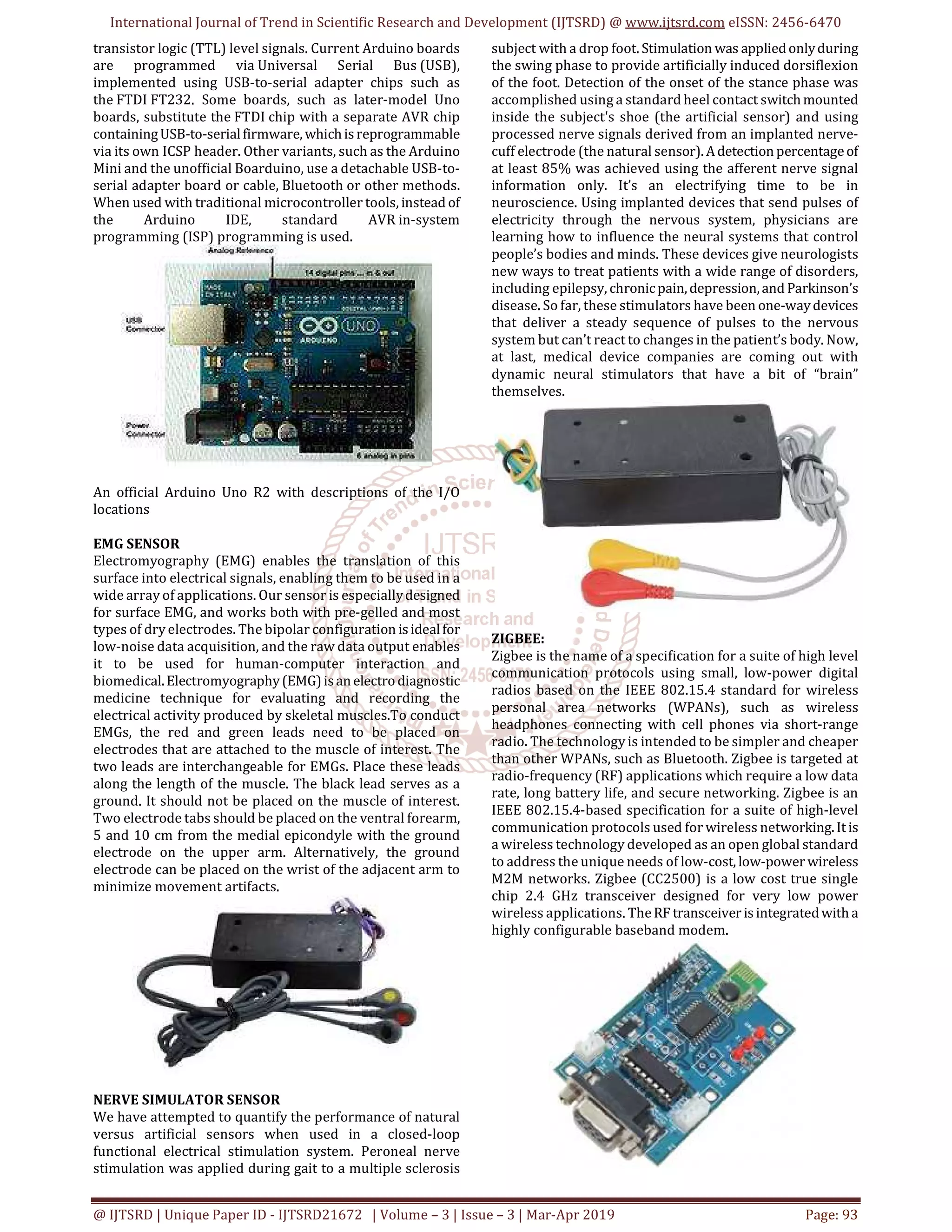
MICROCONTROLLER
Arduino:
It is an open source computer hardware and software
company, project, and user community that designs and
manufactures single-board microcontrollers and
microcontroller kits for building digital devices and
interactive objects that can sense and control objects in the
physical world. The project's products are distributed
as open-source hardware and software, which are licensed
under the GNU Lesser General Public License (LGPL) or
the GNU General Public License (GPL), permitting the
manufacture of Arduino boards andsoftwaredistribution by
anyone. Arduino boards are available commercially in
preassembled form, or as do-it-yourself (DIY) kits.
Arduino board designs use a variety of microprocessorsand
controllers. The boards are equipped with sets of digital and
analog input/output (I/O) pins that may be interfaced to
various expansion boards (shields) and other circuits. The
boards feature serial communications interfaces,
including Universal Serial Bus (USB) on somemodels,which
are also used for loading programs from personal
computers. The microcontrollers are typically programmed
using a dialect of features from the programming
languages C and C++. In addition to using traditional
compiler tool chains, the Arduino project provides
an integrated development environment (IDE) based on
the Processing language project.
The Arduino project started in 2003 as a program for
students at the Interaction Design Institute Ivrea in Ivrea,
Italy, aiming to provide a low-cost and easy way for novices
and professionals to create devices that interact with their
environment using sensors and actuators. Common
examples of such devices intended for beginner hobbyists
include simple robots, thermostats, and motion detectors.
Arduino microcontrollers are pre-programmed with a boot
loader that simplifies uploading of programs to the on-
chip flash memory. The default bootloader of the Arduino
UNO is the optiboot bootloader.[28] Boards are loaded with
program code via a serial connection to another computer.
Some serial Arduino boards contain a level shifter circuit to
convert between RS-232 logic levels and transistor–](https://image.slidesharecdn.com/19realtimeimplementationandinvestigationofwirelessdeviceofelectricalstimulationforperipheralnev-190612074941/75/Real-Time-Implementation-and-Investigation-of-Wireless-Device-of-Electrical-Stimulation-for-Peripheral-Nevers-2-2048.jpg)
![International Journal of Trend in Scientific Research and Development (IJTSRD) @ www.ijtsrd.com eISSN: 2456-6470
@ IJTSRD | Unique Paper ID - IJTSRD21672 | Volume – 3 | Issue – 3 | Mar-Apr 2019 Page: 95
various devices and circuits. These modules are preferred
over seven segments and other multi segment LEDs. The
reasons being: LCDs are economical; easily programmable;
have no limitation of displaying special & even custom
characters (unlike in seven segments). Each pixel of an LCD
typically consists of a layer of molecules aligned between
two transparent electrodes
CONCLUSION
An electrical stimulation implant is demonstrated with>10×
improvement in the depth/volume ratio over existing IC-
based neurostimulators. The fully integrated implant
measures just 2 mm × 3 mm × 6.5 mm (39 mm3, 78 mg), and
operates at a large depth of 10.5 cminatissuephantom. This
significant improvement was enabled by the use of
ultrasound for wireless powering (at safe intensity levels3×
below the FDA limit), and a unique co-design strategy for
complete operation of the implant during the charging
transient of CSTOR . The implant system also implements a
robust DL command/data transfer protocol for fully
programmable stimulation, and a high compliance voltage
(15 V) stimulator for chronic applications. The stimulator
supportsbiphasiccurrent-controlled stimulationwitha wide
range of parameters required for electrical stimulation of
peripheral nerves. The implant also includes a blue LED
which could enable optogenetic stimulation applications in
the future. The capability of the implant is demonstrated
through in vitro characterizations, and electricalstimulation
ex-periments of a sciatic nerve, enabling its use for next-
generation electroceuticals.
FUTURE ENHANCEMENT
Future work involves design of a conformal ultrasound TX
array for optimization of the end-to-end ultrasonic link
efficiency, investigating techniques to mitigate the effect of
implant misalignment, and biocompatible packaging of the
implant for chronic in vivo applications.
IV. REFERENCES
[1] K. Famm, B. Litt, K. J. Tracey, E. S. Boyden, and M.
Slaoui, “A jump-start for electroceuticals,” Nature, vol.
496, pp. 159–161, Apr. 2013.
[2] E. Waltz, “A spark at theperiphery,”NatureBiotechnol.,
vol. 34, no. 9, pp. 904–908, Sep. 2016.
[3] B. Bonaz, C. Picq, V. Sinniger, J. F. Mayol, and D.
Clarencon, “Vagus nerve stimulation: From epilepsy to
the cholinergic anti-inflammatory pathway,”
Neurogastroenterol. Motility, vol. 25, no. 3, pp. 208–
221, Mar. 2013.
[4] J. W. Lee, D. Kim, S. Yoo, H. Lee, G.-H. Lee, and Y. Nam,
“Emerging neural stimulation technologiesfor bladder
dysfunctions,” Int. Neurourol. J., vol. 19, no. 1, pp.3–11,
Mar. 2015.
[5] G. H. Creasey and M. D. Craggs, Functional Electrical
Stimulation for Bladder, Bowel, and Sexual Function,
1st ed., vol. 109. Amsterdam, The Netherlands:
Elsevier, 2012.
[6] M. Brinton et al., “Electronic enhancement of tear
secretion,” J. Neural Eng., vol. 13, no. 1, Feb. 2016, Art.
no.016006.
[7] X. Li, W. A. Serdijn, W. Zheng, Y. Tian, and B. Zhang,
“The injectable neurostimulator: An emerging
therapeutic device,” Trends Biotechnol., vol. 33, no. 7,
pp. 388–394, Jul. 2015.
[8] J. H. Schulman, “The feasible FES system: Battery
powered BION stimulator,” Proc. IEEE, vol. 96, no. 7,
pp. 1226–1239, Jul. 2008.
[9] T. J. Foutz, D. M. Ackermann, K. L. Kilgore, and C. C.
McIntyre, “Energy efficient neural stimulation:
Coupling circuit design and membrane biophysics,”
PLoS One, vol. 7, no. 12, Dec. 2012, Art. no. e51901.
[10] Y. Shih, T. Shen, and B. Otis, “A 2.3 μW wireless
intraocular pressure/temperature monitor,” IEEE J.
Solid-State Circuits, vol. 46, no. 11, pp. 2592–2601,
Nov. 2011.
[11] S. Majerus, I. Makovey, H. Zhui, W. Ko, and M. S.
Damaser, “Wireless implantable pressure monitor for
conditional bladder neuromodulation,” in Proc. 2015
IEEE Biomed. Circuits Syst. Conf., Oct. 2015, pp. 1–4.
[12] R. Muller et al., “A minimally invasive 64-channel
wireless μECoG implant,” IEEE J. Solid-State Circuits,
vol. 50, no. 1, pp. 344–359, Jan. 2015.](https://image.slidesharecdn.com/19realtimeimplementationandinvestigationofwirelessdeviceofelectricalstimulationforperipheralnev-190612074941/75/Real-Time-Implementation-and-Investigation-of-Wireless-Device-of-Electrical-Stimulation-for-Peripheral-Nevers-5-2048.jpg)


![Department_of_Biomedical_Engineering[1] aravindh.pptx aea.pptx](https://cdn.slidesharecdn.com/ss_thumbnails/departmentofbiomedicalengineering1aravindh-250805025626-c9e28700-thumbnail.jpg?width=640&height=640&fit=bounds)


