Mysore Call Girls 8617370543 WhatsApp Number 24x7 Best Services
938-Article Text-4728-1-10-20100512.pdf
1. CHAPTER 35
EROSION AND CORROSION ON MARINE STRUCTURES, ELWOOD, CALIFORNIA
H. J. Schaufele
Engineering Department, Signal 011 and Gas Company
Los Angeles, California
INTRODUCTION
The sole purpose o~ this paper is to present to the public more than twenty
years' experience acquired in designing ~or, and eventually combating, the unusual
~orces of nature acting on marine structures in exposed waters. The structural
design will naturally be determined by the use the project is called upon to serve
and the standards of the designer. This particular phase o~ the overall picture,
with the aid o~ available meteorological and oceanographical data ~or a speci~ic
area offers no particular difficulty in structural design.
The subject matter presented herein re~ers to observations made among the
various pier and oilwell ~oundations constructed in the Elwood Field, Cali~ornia,
during the interval between 1929 and 1935, and major maintenance problems to date.
Where protective measures made at the time o~ installation are explained, they
re~er to our own speci~ic works, while the general observations in the ~ield are
con~ined to no one particular structure or type o~ design.
LOCATION
For several miles in the Elwood area, the coast line is marked by a very
steep shale escarpment, 30 ~t. to 90 ~t. high, rising ~rom the beach. At inter-
vals this escarpment has been eroded by streams ~rom the mountains which have cut
canyons that are perSistent well out to sea, although ~illed with sand and silt to
the level o~ the present ocean ~loor. These ~ormer canyons, as ~ar as we have
tested with jets, indicate depths up to 90 ~t. ~rom the ocean ~loor down to origi-
nal shale.
The beach line, extending seaward, is a relatively smooth shale sur~ace,
dropping seaward about 40 ~t. in depth in 2500 ~t. From the base o~ the escarp-
ment this beach is intermittently covered with a mantle o~ sand varying in thick-
ness up to 8 ~t. ~rom season to season. Beyond the breaker line to approximately
a depth of 60 ft., there are extensive beds of kelp.
DESIGN
On the first 1650 ~t. seaward o~ the pier, a three-pile bent o~ 8 in. x 8 in.
--32 lb. "H" section was used. Previous to driving, the piles were wire brushed
to remove mill scale, washed to remove dust and loosened scale, and given two
coats o~ asphalt chromate emulsion, having a minimum one-sixteenth of an inch of
coating.
The ~irst thirteen bents seaward, or those in the normal breaker line, were
protected by driving a 14 in. diameter 3/16 in. thick 8 ~t. long steel cylInder
over the pile through the sand into the shale, jetting the interstitial space
clean of sand and ~illing the same with a 1:2 cement grout.
The reasoning behind this deviation ~rom standard practice in the ~ield was
the experience of the designer, who had seen steel piles o~ structural shape cut
of~ in the breaker line by abrasion o~ sand in suspension, whereas round shapes
survived, such as the old Olympic Club pier on the San Francisco beach.
This detail o~ design proved to be very e~~ective as the adjacent piers have
had to have piling in the breaker range replaced or protected within five years
i afte~ installation.
}
On one pier we acquired by purchase, the "H" sections in the breaker area, at
the ~irst sign o~ scouring, were protected by boxing the exterior o~ the pile with
326
2. EROSION AND CORROSION ON MARINE STRUCTURES, ELWOOD, CALIFORNIA
creosoted two inch thick planks, securing same with 1/2 in. x 2 in. galvanized )
bands top and bottom. Incidentally, after fifteen years, the wood is intact but
the top bands are cut through. Reference to illustrations will show the wisdom of
this choice on new work and the boxing of piles already driven (Figs. 1 and 2) .
The two basic divisions of the structures, as constructed, were the well or
derrick foundations, and the working area or pier approach.
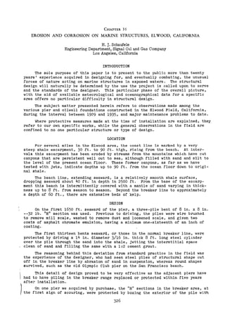
Fig. 1. ABRASION IN BREAKER LINE
- A -
General Effect on Unprotected H Piling.
- B -
Protection Provided in the Planning 8 in. H Piling, 14 in. diameter,3/16 in.thick-
ness driven cylinders, interstitial space cleaned out and filled with 1:2 cement
grout. In service 21 years without maintenance or coating of any type.
327
3. COASTAL ENGINEERING
Fig. 2. ABRASION IN BREAKER LINE
-B- -C-
- A -
Protection Provided after Construction 10 in. H Piling, 2 in. x 12 in. creosoted
boxing secured in position by 1/2 in. x 2 in. galvanized clamps. In service 16
years. Condition: Timber - good; clamps - cut through at corners.
- B -
Attempts to Protect after Construction. Same as cut A except untreated timber.
- C -
Attempt to Protect after Construction. Spiral-wrapped reinforced concrete. Failed
when sheet iron form failed. Still protected, however. Limited to Tidal Range.
The various interests through their respective engineering depar.tments set
varying load conditions and it is worthy of note that there has been no failure
through loading up to now on any of the structures -- twenty-one years in service--
that were originally designed for a fifteen year life, notwithstanding the fact
that today's transportation and drilling equipment is twenty-five to fifty percent
heavier than that of twenty years ago.
The premises of design and protection adopted by the Signal Oil and Gas Com-
pany on their structures will be discussed in detail from here on, giving the
thinking behind each deviation from precedent, the results of the choice after a
twenty-year service, and the changes that suggest themselves if we were to start
off anew.
328
4. EROSION AND CORROSION ON MARINE STRUCTURES, ELWOOD, CALIFORNIA
CHOICE OF MATERIALS
Inasmuch as the ocean bottom is shale, wood piling was out -- except in a few
cases where piers traversed aforementioned silt-filled shale depressions on the
ocean bottom.
Little was actually known about the effect of pile cross-section pattern on
the drag coefficient in 1929. Steel piling seemed to be the only solution, and
because of the immediate availability and economics, structural sections were used.
Our experience to date indicates· the choice of steel was right, but the cross-
section or pattern of the pile was wrong. The superstructure, consisting of caps,
jOists, and deck, was built of untreated structural grade Oregon pine. ,-
Progressively, the next item we considered was the location of the welded
transverse and longitudinal angle bracing. When you consider the long unsupported
length of the piles or the high slenderness ratio, it is apparent that bracing of
some kind is required. It is impractical to do this below the water line and too
close to sea level. The braces gather floating kelp and debris. This becomes a
hazzard because of the additional weight, and especially because of the increased
area exposed to wave action. Hence, by observation of an existing pier in the
area, we decided our first bracing should be 8 ft. above the high tide line. We
have never lost a rod or brace in twenty years and have never had to remove kelp
suspended from the bracing.
We next chose the most suitable deck elevation above mean high water. Prece-
dent indicated 20 ft.; however, we added 2 ft. to this and used 22 ft. as our deck
elevation. The reasoning we used was based on observation that waves build up
just before breaking. So far we have had no trouble from waves lifting the bottom
of our deck system; howeyer, a few high waves have reached the under side of the
superstructure. on other piers in the vicinity.
In 1935, six years after the construction of the original 1650 ft. pier, it
was deemed advisable to add approximately 800 ft. to the original pier to provide
drill sites as close as possible to the axis of the anticline (or top of oil struc-
ture). The reason for bringing this information into the paper is to present the
variation in design employed and results obtained therefrom.
On advice of the consultant, protection (coating) on piling was deemed of
little value and he recommended the price of coating had better be spent in pro-
viding thicker steel. Hence, in this section of pier a four-pile bent of 10 in. x
10 in. -- 54 lb. "H" Section, with no coating of any kind was used. Now, bear in
mind the original pier built in 1929 consisted of a three-pile bent of 8 in. x
8 in. -- 32 lb. piles coated, while this new section built in 1935 consisted of
four 10 in. x 10 in. -- 54 lb. piles uncoated. The bracing and superstructure are
similar.
The wisdom in coating the piling as a protection against oxidation above the
tide range is again illustrated by the pictures (Fig. 3). All hardware through-
out, such as nails, drifts, bolts, nuts and rods were hot-dipped galvanized. The
concrete mix for well foundations such as derrick legs, cellars and scupper decks
was scientifically worked out. San Gabriel sand and gravel were used and the mix
called for seven sacks of high silica cement per cubic yard with a maximum slump
of six inches. The concrete work was coated with bitumastic immediately after re-
moving the forms.
In resume, the only protective measures taken during construction were coat-
ing the piling, jacketing the piling in the breaker line, ventilating all lumber
to the fullest, creosoting all lumber bearings and laps, using galvanized hardware
throughout and coating all freshly stripped concrete. It is worthy of note here
that after twenty-one years' exposure, the piers are in continuous service today
with a minimum of replacement and maintenance.
Regular visual inspections of exposed works above the sea level are made by
coring lumber and calipering steel. Periodic subsurface inspections are made by
divers, again calipering the steel after removal of the organic growth. The Sig-
nal Oil and Gas Company have taken the caliper readings as furnished by the diver
and recalculated areas and section moduli and from this data we are able to have a
close check on our original premises of design.
329
5. COASTAL ENGINEERING
Fig. 3. ATMOSPHERIC CORROSION
.-
.:..~ ..,"'. '..';.:"
~...." "-..t:.. ~.r...
4> ~
-A- -B-
ELECTROCHEMICAL CORROSION
- C - - D -
-A- Very severe case of oxidation in atmosphere above tide range. 10 in. H Pile,
0.564 in. web thickness; no protective coating. In service 16 years.
-B- 8 in. H pile, 0.300 in. web thickness, coated with 1/16 in. of Asphalt Chro-
mate Emulsion. In service 21 years. Never retouched.
-C- At Base of Piling beyond the sand line in deep water where the bottom is mud
and decaying kelp. This is a highly anaerobic area.
-D- Action on Auxiliary Non-structural Sleeves placed by diver at base of piling.
Twenty-one years of observation on all piers in the vicinity has brought forth
the following recommendations:
Piling, breaker line or sand bottom area. All piling should be cylindrical or
circular in cross section to provide as near as possible a streamline flow past the
pile for any direction of wave impingement. An auxiliary sleeve over the pile of
sufficient length to cover same between the limits of sand depth, is desirable.
This choice of section provides an equal section modulus for any axis; also, if
paints, wrapping, etc., are used, the circular cross-section provides less com-
parable surface area to cover and no angles, corners or sharp edges where it is
difficult to build up coatings.
6. EROSION AND CORROSION ON MARINE STRUCTURES, ELWOOD, CALIFORNIA
Piling should be spaced a minimum of five diameters for a dampening of eddies
set up by adjacent piling. The piling should be filled with concrete for addi-
tional strength and stiffness to resist any distortion, or the pile should be
sealed off or neutralizing agent should be added to prevent interior corrosion.
structural sections in the breaker range can be protected by boxing, preferably
with creosoted plank secured with heavy metal straps.
Coatings above the low tide range, certainly in our case, have proved to be
better than the additlonal uncoated steel.
The above recommendations are based on the following observations:
(Breaker line) In about three years, noticeable wear and sharpening of
flanges was noted where structural shapes were used. In five years the cross-
section was considerably reduced and lenticular holes appeared in the webs.
("H" pilings) Those oriented so the web was normal to the wave direction
were especially susceptible to abrasion. Many piers have had their piling replaced
or reinforced in the breaker line within five years.
The condition of the piling given a protective coating twenty years ago is a
convincing argument in favor of a protective coating at least for oxidation in the
zone above the water line.
(Deep water piling inspection) Cleaning a selected number of piling from the
underside of the cap to the ocean floor and observing and calipering same dis-
closed the following, proceeding up the pile:
No sand cut or abrasion was noticeable.
At approximately 2 ft. above the bottom, a highly anodic area was .found with
a noticeable loss of section. This may be related to the point of flexure; how-
ever, the environment is highly anaerobic, common to harbors and areas of decaying
kelp. We corrected this by having a diver add metal sleeves to the piling and sub-
sequent inspections have shown this has corrected the condition. The metal loss,
whether it be chemical or electrolytic, is now from the auxiliary metal jacket
rather than the pile and we believe that no further loss of metal will take place
at this critical pOint.
When you consider that on an average of 6 sec. wave periods in the space of
one year you have 5,350,000 reversals of stress, multiplied by twenty years, flex-
ure might well be responsible for at least a part of the condition explained above
(Fig. 4).
Proceeding up the pile, anodic pits were found at various points. They fol-
lowed no specific pattern or location and while not deemed hazardous, locations
and lead impressions were carefully made for future comparison.
Our next perceptible loss of section on uncoated piling was above the water
in the vicinity of the horizontal bracing welded to the piling. The loss of pile
cross-section can be seen by eye on removal of the laminations of rust. The
flange thickness is reduced to about sixty percent of its original thickness and,
strangely, in a few cases, the webs are badly corroded. This condition does not
exist to such a marked degree, if at all, where the piling and joints were coated
twenty years ago. This again is a point of restraint and flexure. The only cure
so far is removal of the section and welding in a "dutchman".
The writer recently attended the annual Sea Horse Convention at Kure Beach,
North Carolina, where salt water corrosion was the sole topic. The general obser-
vation brought forth paralleled what we have here on the West Coast, with recom-
mendations for prolonging the life of steel piling similar to those we are taking
or have taken.
From the study of the subject discussed at the convention, it certainly con-
vinces one that each environment has its own specific problems.
As of this instant, we are testing various types of pile protection such as
paints, somastic coating, metal spray, galvanizing and also cathodic protection,
which seems to offer a solution at least to our under-water problems.
331
7. COASTAL ENGINEERING
Fig. 4. STRESS CORROSION
- A -
- B - - C -
-A- Typical Corrosion in vicinity of restraint showing laminations of rust. In
service 16 years. No coating protection.
Typical Corrosion in vicinity of restraint with rust removed. Note loss of
section on the flange. In service 16 years.
Note absence of above conditions where steel was coated with Asphalt Chromate
Emulsion. In service 21 years.
Bracing. Bracing should be of a minimum, located above normal wave heights
and in areas where kelp is prevalent, consideration should be given to kelp load-
ing. The section, where possible, should be round to reduce the drag coefficient
of waves and the ease of re-coating. The principal objection to round section is
fabrication.
332
8. EROSION AND CORROSION ON MARINE STRUCTURES, ELWOOD, CALIFORNIA
Timber. The subject of wood preservation is a science by itself and all I can
relate here are the precautions taken on our works to try to insure our superstruc-
ture and the results obtained. Again, the choice of untreated timber over treated
lumber, even for fifteen years, is a matter of environment. All lumber was rough
structural grade. All bearings were mopped with hot creosote. All laps were
mopped with hot creosote. All lumber was spaced or gauged insofar as possible to
provide free air circulation. Deck planks were gauged 3/4 in. All nails, drifts,
bolts, etc., were galvanized.
After twenty years, aside from a few planks, the original deck and the origi-
nal joists remain; some few caps, possibly sixteen percent, have been reinforced
due to heart rot from water entry through checks.
By all means, provide as much air circulation as possible; keep the top sur-
faces of caps cleaned of all earth or wood fibre that might sift through the deck
spacing and form a damp mat and induce decay from the top. When fungi or dry rot
have taken over and auxiliary members are required, remove the ailing timber. The
presence of such timber is a source of fungi spore and it is no longer a structural
component of the work.
Fig. 5. CONCRETE IN SALT WATER ENVIRONMENT
-A- -B-
r
- C - - D -
-A- Mass Concrete in Wave Area.
-B- Vertical Rise from Sheet Pile Forms.
-C- Mass Concrete in 1/4 in. Steel Shell above high tide line. Note weld failures.
-D- Mass Concrete in 1/4 in. Steel Shell above high tide line. Note shell failure.
333
9. COASTAL ENGINEERING
concrete. Concrete offers the same picture as anywhere else along the South-
ern California coast. It "grows," whether reinforced or mass concrete. We have
had success with high-silica cements and a scientifically graded aggregate for
density, stripping and coating as soon as possible to exclude moisture. This also
has protected ordinary Portland cement concrete.
There are instances along the coast where concrete cylinders 13 ft. in di-
ameter have increased their diameter approximately 6 in. and have grown approxi-
mately 4 in. in height. Other cases have occurred in which cylinders of 1/4 in.
plate and 6 ft. diameter, filled with concrete, have either ruptured the weld or
the steel failed.
Reference to accompanying photographs should emphasize the necessity of in-
vestigation of the chemical reaction between cements and aggregate in a damp en-
vironment (Fig. 5).
In summation, there is no panacea for the caprices of nature in its never-
ending task of destruction and building. The insatiable appetite of nature must
have sustenance, preferably coatings and/or anodes rather than structural members.
In designing, the economic comparison between long life with costly prepara-
tion to receive and ultimate application of coatings, must be made with shorter
life using more frequent applications of a less expensive coating. In fact, in
the original design provision might well be made for the ease of ultimate replace-
ment of certain structural members.
The recent convention at Kure Beach, North Carolina, more than ever convinced
the writer that each installation is a separate problem. Figures on the average
i.p.y. (inches per year) losses by oxidation, abrasion~ etc., of timber, steel,
galvanizing, etc., certainly were not applicable to Elwood structures. To keep
various construction members, -- timber, piling, etc., -- in balance, it is neces-
sary to inspect, repair or replace at regular time intervals.
In a study of this report and accompanying pictures (Figs. 1 - 5), the reader
should bear in mind that many of the illustrations are of structures before re-
placement of members and others are of structures already razed or in the process
of being razed. Where structures are in service, every possible known means of
maintenance is being used to preserve them.
334