Downloaded 34 times
![6.1.2 Protection of the strings against reverse a drop of the direct voltage, the inverter certainly shuts
current down and probably is disconnected from the grid. Nor-
6 Protection against overcurrents and overvoltages
mally the shut down times of the inverter are of the order
Due to shading or fault a string becomes passive, absorbing of some milliseconds, while the disconnection times may
and dissipating the electric power generated by the other be of the order of some dozens of milliseconds. In the
strings connected in parallel to the same inverter through interval between the shut down and the disconnection,
a current which flows through the string under considera- the grid might cause the above mentioned effect, while
tion in a reverse direction with respect to that of standard the internal capacitors, if involved, participate up to their
operation, with possible damages to the modules. complete discharge.
These are able to withstand a reverse current ranging The effects on the short-circuit of both the grid as well
from 2.5 and 3 Isc (IEC TS 62257-7-1). Since with x strings as of the internal capacitors are just of transitory nature
and usually are not such as to affect the dimensioning
in parallel connected to the same inverter the highest
of the protective, switching and disconnection devices
reverse current is equal to Iinv = (x-1) . 1.25 . Isc, it is not
positioned on the d.c side. However, it is necessary to
necessary to protect the strings if Iinv ≤ 2.5 . Isc that is consider case-by-case the advisability of such choice:
(x-1) . 1.25 ≤ 2.5 ⇒ x ≤ 33. in particular, a very high discharge current of the capaci-
tors, combined with long time constants, might force to
increase the current breaking capacity of the circuit-
6.1.3 Behaviour of the inverter breakers.
The contribution to the short-circuit on the DC side of the
inverter may come from the grid and from the discharge
6.1.4 Choice of the protective devices
of the capacitors inside the inverter. As regards the protection against the short-circuits on the
The grid current is due to the recirculating diodes of the DC side, the devices shall be obviously suitable for DC
bridge inverter which in this case act as a bridge recti- use and have a rated service voltage Ue equal or higher
fier. Such current is limited by the impedances of the than the maximum voltage of the PV generator which is
transformer and of the inductors belonging to the output equal to 1.2 Uoc4 (IEC TS 62257-7-1).
circuit and by the protection fuses of the inverter on the
AC side chosen so that they can limit the thermal effects Moreover the protection devices shall be positioned at
of possible internal faults on the semiconductors. As a the end of the circuit to be protected, proceeding from
consequence the I2t passing through will be normally the strings towards the inverter, that is in the various
reduced. Indicatively a final current value (internal ca- subfield switchboards and inverter switchboards since
pacitors completely discharged) of 10In can be an upper the short-circuit currents come from the other strings,
limit value. This current is present in case of inverter with that is from the load side and not from the supply side
galvanic insulation at 50Hz, while it is null in case of in- (IEC TS 62257-7-1).
verter without transformer. In fact these inverters usually
have an input DC/DC converter so that the operation on
In order to avoid unwanted tripping under standard opera-
a wide voltage range of the PV generator is guaranteed;
tion conditions, the protective devices positioned in the
this converter, due to its constructive typology, includes at
least one blocking diode which prevents the contribution subfield switchboards (device A in the Figure 6.1) shall
of the grid current to the short-circuit. have a rated current In5:
The discharge current of the capacitors is limited by the
In ≥ 1.25 . Isc [6.1]
cables between inverter and fault and exhausts itself with
exponential trend: the lowest the impedance of the cable These devices shall protect:
stretch, the highest the initial current, but the lowest the • every single string against the reverse current;
time constant of the discharge. The energy which flows • the connection cable6 string to subswitchboard (cable
is limited to that one initially stored in the capacitors. 1 of Figure 6.1) if the latter has a current carrying ca-
Moreover, if a blocking diode or other similar device is in pacity lower than the maximum short-circuit current of
series with one of the two poles, this contribution to the the other x-1 strings connected to the same inverter
short-circuit is null. switchboard7, i.e. if:
In each case, the short-circuit on the DC side causes I < I = (x - 1) . 1.25 . I [6.2]
z sc2 sc
3
The blocking diodes can be used, but they do not replace the protections against 4
Uoc is the no load voltage coming out of the strings (see Chapter 3).
overcurrent (IEC TS 62257-7-1), since it is taken into consideration the possibility that
the blocking diode does not work properly and is short-circuited. Moreover the diodes 5
For thermomagnetic circuit-breakers the [6.1] becomes Ioverload ≥ 1.25 . Isc, while for mag-
introduce a loss of power due to the voltage drop on the junction, a loss which can be netic only circuit-breakers Iu ≥ 1.25 . Isc so that their overheating can be avoided.
reduced by using Schottky diodes with 0.4V drop instead of 0.7V of conventional diodes.
However the rated reverse voltage of the diodes shall be ≥ 2 Uoc and the rated current ≥ 6
Protection against short-circuit only because Iz ≥ 1.25 . Isc.
1.25 Isc (CEI Guide 82-25).
7
The short-circuit Isc1 = 1.25 . Isc (fig. 6.1) (Figure 6.1) is unimportant because the string
cable has a current carrying capacity not lower than 1.25 . Isc.
Photovoltaic plants 43](https://image.slidesharecdn.com/pvlez6-120511122132-phpapp01/85/Pv-lez-6-2-320.jpg)
![Technical Application Papers
To the purpose of protection for the string, the rated 6.2 Protection against overcurrents on AC side
current of the protective device (either thermomagnetic
6 Protection against overcurrents and overvoltages
circuit-breaker or fuse) must not exceed that one declared Since the cable connecting the inverter to the point of
by the manufacturer for the panel protection (clause connection with the grid is usually dimensioned to obtain
6.1.2); if no indications are given by the manufacturer, a current carrying capacity higher than the maximum cur-
the following is assumed (IEC TS 62257-7-1): rent which the inverter can deliver, a protection against
overload is not needed. However the cable must be
1.25 . Isc ≤ In ≤ 2 . Isc [6.3]
protected against a short circuit supplied by the grid10
In spite of the simplicity of use of fuses, when sizing and through a protective device positioned near the point of
choosing these devices it is necessary to take into account
parallel with the grid.
that they not only must have a rated current obtained by
the relationship [6.3], but that they must have a trip char- To protect such cable the main circuit-breaker of the con-
acteristic type gR (i.e. suitable for the protection of circuits sumer plant can be used if the specific let-through energy
by means of semiconductors), they must be mounted is withstood by the cable. However, the trip of the main
on fuse holders and they must be able to dissipate the circuit-breaker put all the consumer plant out of service.
power generated under the worst operating conditions.
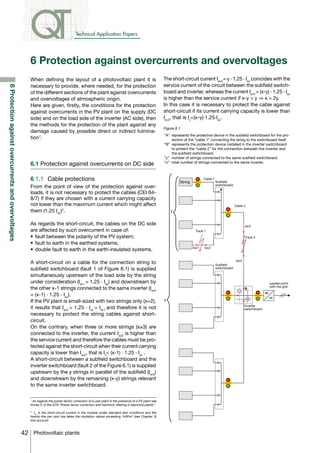
In the multi-inverter plants (Figure 6.2), the presence of
To the purpose of protection for the connection ca-
ble, the protective device must be chosen so that the one protection for each line allows, in case of fault on
following relation is satisfied for each value of short- an inverter, the functioning of the other ones, provided
circuit (IEC 60364)8 up to a maximum of (x-1) . 1.25 . Isc: that the circuit-breakers on each line are selective with
the main circuit-breaker.
(I2t) ≤ K2 S2 [6.4]
where: Figure 6.2
(I2t) is the Joule integral referred to the short-circuit dura-
tion (in A2s);
K is a characteristic constant of the cable depending on
the type of conductor and on the insulating material;
S is the cross-sectional area of the cable (in mm2).
The breaking capacity of the device must not be lower
than the short-circuit current of the other n-1 strings, Point of
parallel with
that is: the grid
Icu ≥ (x-1) . 1.25 . Isc [6.5]
The devices in the inverter switchboard must protect
against the short-circuit the connection cables subfield
switchboard-inverter switchboard when these cables have
a current carrying capacity lower than Isc4 = (x-y) . 1.25 . Isc9
(Figure 6.1). In this case these devices shall satisfy the
relations [6.1] and [6.4], while their current carrying ca-
pacity shall not be lower than the short-circuit current of
the other n-m strings, that is:
6.3 Choice of the switching and disconnecting
Icu ≥ (x-y) . 1.25 . Isc [6.6] devices
In short, the cable for the connection inverter switchboard The installation of a disconnecting device on each string
to inverter must not be protected if its current carrying is advisable in order to allow verification or maintenance
capacity is chosen at least equal to (CEI 64-8/7): interventions on the string without putting out of service
Iz ≥ x . 1.25 . Isc [6.7] other parts of the PV plant (CEI Guide 82-25 II ed.)11.
8
For the magnetic only circuit-breaker it is necessary, if possible, to set the protection 10
The inverter generally limits the output current to a value which is the double of its
function at a value equal to the value Iz of the cable in order to determine the tripping of the rated current and goes in stand-by in few tenths of seconds due to the trip of the internal
device when the short circuit current exceeds the current carrying capacity of the protected protection. As a consequence, the contribution of the inverter to the short-circuit current
cable. Besides, it is possible to use a magnetic only circuit-breaker if the number of strings is negligible in comparison with the contribution of the grid.
connected to the same inverter is maximum 3; otherwise for the protection of the string it
is necessary to use a thermomagnetic circuit-breaker chosen according to [6.3]. 11
When an automatic circuit-breaker is used the switching and disconnecting function
is already included.
9
The short-circuit current Isc3 = y . 1.25 . Isc (Figure 6.1) is unimportant since the string
cable has a current carrying capacity not lower than y . 1.25 . Isc.
44 Photovoltaic plants](https://image.slidesharecdn.com/pvlez6-120511122132-phpapp01/85/Pv-lez-6-3-320.jpg)


This document discusses protection against overcurrents and overvoltages in photovoltaic plants. It addresses protection of different sections of the plant from overcurrents on the DC and AC sides. On the DC side, it discusses protections for cables, strings, and behaviors of inverters during faults. Cable protections must be rated to withstand maximum short-circuit currents from other connected strings. String protections must not exceed manufacturer ratings. Inverters may contribute to faults from grid currents or capacitor discharges. On the AC side, cables connecting inverters to the grid need protection from grid faults. Circuit breakers must be selective to isolate only faulty sections of multi-inverter plants. Disconnecting devices on individual strings are recommended