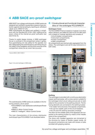
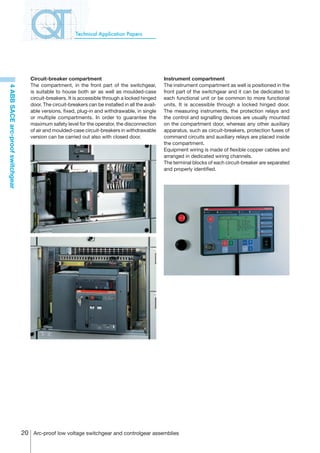
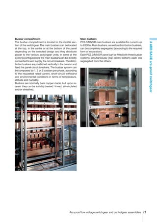
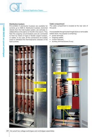
This document provides an overview of low voltage switchgear and controlgear assemblies. It discusses the electric arc phenomenon and its effects, as well as internal arc-proof switchgear assemblies that provide protection against electric arcs. It also describes ABB SACE arc-proof switchgear models, including their constructional and functional characteristics. The document contains three or fewer sentences.
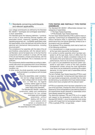
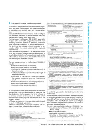
![The impedance used to verify the test current shall be A. calibration test
the same used during the test. The current carrying capacity of the circuit is verified with
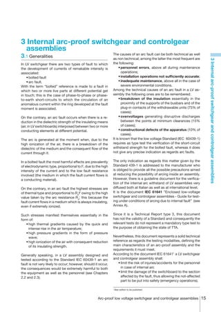
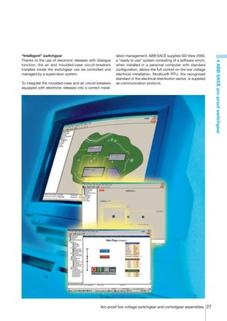
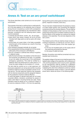
Annex A: Test on an arc-proof switchboard
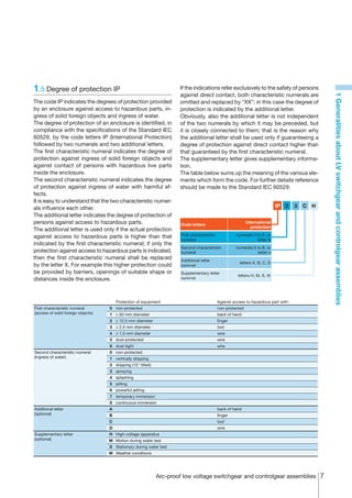
The test duration is given by the manufacturer. It is 65 kA test current at 462 V (440 V+5%) rated voltage.
chosen according to the time response of the electrical The table below shows the values measured during the
protection devices. If details regarding these devices are test.
not known, a power supply duration of at least 0.1s is
applied. Normally this duration should not exceed 0.5s. 1_I1 2_I2 3_I3
Average
values
Symmetrical current [kA] 65.9 65.0 65.7 65.5
A positive test result is obtained when the above men-
Peak current [kA] -129 144 -106
tioned criteria are fulfilled. Start [ms] 75.8 76.5 75.9
Three tests have been carried out: End [ms] 409.4 408.5 409.4
A. calibration test; Cosj 0.16
B. test with arc ignition at the terminals of an outgoing unit;
Legend:
C. test with arc ignition between the main busbars. • 1_I1, 2_I2, 3_I3: currents in the three phases
• Cosj: power factor
The figure below reports the oscillogram showing the
line-to-line voltages (7_Ur1, 8_Ur2, 9_Ur3) and the cur-
rents (1_I1, 2_I2, 3_I3) in the three phases.
4_Ur4 kV
k/div
-
250
kA
_I
250 k/div
-250
kV
7_Ur
k/div
-
5_Ur5 kV
k/div
-
250
2_I2 kA
250 k/div
-250
kV
8_Ur2
k/div
-
kV
6_Ur6
k/div
-
250
kA
3_I3
250 k/div
-250
kV
9_Ur3
k/div
-
0
V
0_Cam
0/div
-0
0 20 40 60 80 00 20 40 60 80 200 220 240 260 280 300 320 340 360 380 400 420
20 ms/div ms
Arc-proof low voltage switchgear and controlgear assemblies 29](https://image.slidesharecdn.com/arcproof-1sdc007105g0201-120914201946-phpapp01/85/Arc-proof-1-sdc007105g0201-30-320.jpg)
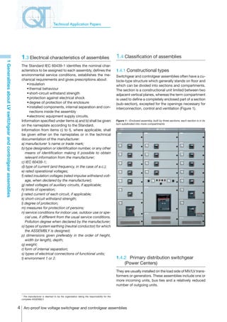
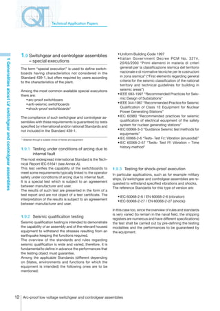
![Technical Application Papers
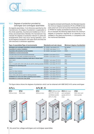
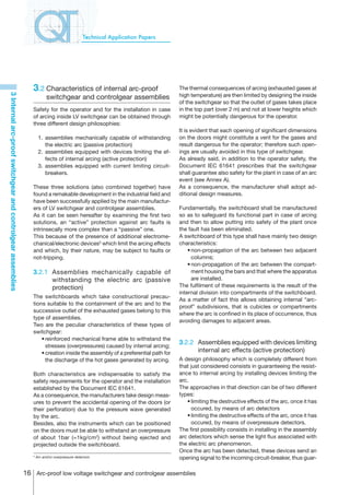
B. test with arc ignition at the terminals of an outgoing unit The table below shows the values measured during the
After the circuit calibration an arc-proof test shall be test.
Annex A: Test on an arc-proof switchboard
carried out applying for 0.3 s a test current of 65 kA at a
voltage of 462 V (440 V+5%). 1_I1/4_Ur4 2_I2/5_Ur5 3_I3/6_Ur6
The arc has been initiated between the upper terminals Maximum current [kA] 10.3 19.8 -19.8
of a circuit-breaker of one of the outgoing units: the du- Maximum voltage [V] 786 349 -746
ration of the current has resulted to be only 7.7 ms due Arcing energy [kJ] 1.28 22.7 22.3
to self-extinction of the arc. As a consequence also the Total specific energy [A2s] 4.38E+04 1.43E+06 1.52E+06
Arcing power [W] 6.98E+06 5.52E+06 7.55E+06
current value results to be reduced.
Arc duration [ms] 1.1 7.7 7.6
The arc has extinguished within the first half of the full
intended test duration without being ignited again and Legend:
• 1_I1, 2_I2, 3_I3: currents in the three phases
therefore, in compliance with the Technical Report IEC • 4_Ur4, 5_Ur5, 6_Ur6: arcing voltages
61641, such test shall be repeated using the same point • Cosj: power factor
of initiation as for the first test.
Since the arc has extinguished within the first half of the The figure below reports the oscillogram showing the
full intended duration also during this repetition, a further arcing voltages (4_Ur4, 5_Ur5, 6_Ur6), the line-to-line
test is not required. voltages (7_Ur1, 8_Ur2, 9_Ur3) and the currents (1_I1,
2_I2, 3_I3) in the three phases. In the oscillogram the
short duration of the currents due to the fast arc extinc-
tion can be noticed.
4_Ur4 kV
k/div
-
50
kA
_I
50 k/div
-50
kV
7_Ur
k/div
-
5_Ur5 kV
k/div
-
50
2_I2 kA
50 k/div
-50
kV
8_Ur2
k/div
-
kV
6_Ur6
k/div
-
50
kA
3_I3
50 k/div
-50
kV
9_Ur3
k/div
-
2
V
0_Cam
2/div
-2
0 20 40 60 80 00 20 40 60 80 200 220 240 260 280 300 320 340 360 380 400 420
20 ms/div ms
30 Arc-proof low voltage switchgear and controlgear assemblies](https://image.slidesharecdn.com/arcproof-1sdc007105g0201-120914201946-phpapp01/85/Arc-proof-1-sdc007105g0201-31-320.jpg)
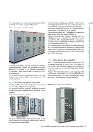
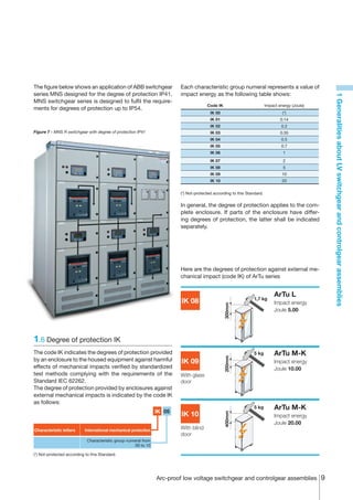
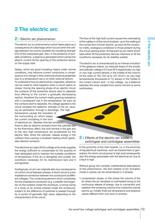
![C. test with arc ignition between the main busbars The table below shows the values measured in the test.
A further test, always 65 kA at 462 V, is carried out with arc
Annex A: Test on an arc-proof switchboard
initiation between the main busbars; the actual duration 1_I1 2_I2 3_I3
of the current has resulted to be 0.3 s, with temporary Peak current [kA] 55.7 -62.3 46.6
self-extinctions of the arc on the phases L1 and L3 and Duration [ms] 301.37 301.37 216.76
subsequent re-ignition. Specific energy [A2s] 2.53E+08 2.97E+08 1.12E+08
The figure below reports the oscillogram showing the
arcing voltages (4_Ur4, 5_Ur5, 6_Ur6), the line-to-line
voltages (7_Ur1, 8_Ur2, 9_Ur3) and the currents (1_I1,
2_I2, 3_I3) in the three phases.
4_Ur4 kV
k/div
-
00
kA
_I
50 k/div
-00
kV
7_Ur
k/div
-
5_Ur5 kV
k/div
-
00
2_I2 kA
50 k/div
-00
kV
8_Ur2
k/div
-
kV
6_Ur6
k/div
-
00
kA
3_I3
50 k/div
-00
kV
9_Ur3
k/div
-
2
V
0_Cam
2/div
-2
0 20 40 60 80 00 20 40 60 80 200 220 240 260 280 300 320 340 360 380 400 420
20 ms/div ms
Arc-proof low voltage switchgear and controlgear assemblies 31](https://image.slidesharecdn.com/arcproof-1sdc007105g0201-120914201946-phpapp01/85/Arc-proof-1-sdc007105g0201-32-320.jpg)