This document evaluates cable parameters for variable frequency drive (VFD) applications. It examines different cable types, including PVC-nylon cables which are commonly used but can be misapplied for VFDs. The document tests cables designed for VFDs, such as XLPE insulated cables with foil/braid shielding. It finds these cables help match the impedance of the motor better, lowering peak voltages and reducing insulation stress to increase motor and cable life. Cables with higher impedance resulted in lower peak voltages at the motor terminals. The document provides guidelines for selecting properly designed cables to optimize VFD system performance and reliability.
RG58 and LMR400 all coax cables. This article is going to talk about the detailed information about RG58 and LMR400, and interpret the differences between them.
If you want to learn more, try to follow the below link to see the article.
https://www.utmel.com/components/rg58-vs-lmr400-which-one-is-better?id=1492
On-Chip ESD Protection Achieving 8kV HBM Without Compromising the 3.4Gbps HDM...Sofics
To maintain signal integrity on HDMI TMDS interfaces ESD protection requires careful design. Moreover, due to direct consumer interaction higher ESD specifications are requested. This paper presents results for an HDMI circuit achieving 8kV HBM without compromising the 3.4Gbps data rate through the use of low capacitive on‐chip ESD clamps.
CMP PX2K Cable Glands (Barrier Glands Exd Flameproof with ATEX Certification for Hazardous Areas)
Cable Gland Size 20S/16 (M20) 1/2" NPT Entry Thread Standard, 3/4" NPT Optional
Cable Gland Suits Cable Diameters 6.1mm-11.5mm
CMP PX2K barrier cable glands are ATEX certified and suitable for use with all forms of equipment protection permitted in Zone 1, Zone 2, Zone 21 and Zone 22. Flameproof compound filled barrier glands for cable terminations within ATEX areas are supplied with a "universal" reversible armour ring to suit all types of armoured cables - this includes steel wire armoured (SWA), steel tape armoured (STA) and wire braided cables for installation within hazardous areas. Barrier cable glands provide a compound barrier seal around the cable conductors and an environmental seal on the cable outer sheath. The CMP PX2K cable gland provides a mechanical cable retention and electrical continuity via the cable armour termination. A combined detachable armour cone and compound tube, together with AnyWay universal cable clamping ring arrangement allows the cable to be easily disconnected from the electrical equipment and easily re-connected. This cable gland feature facilitates remote make off procedures when the cable termination is to be conducted in confined spaces or in areas of restricted access.
Cable Glands are suitable for following cable types - Wire Braid Armour, Single Steel Wire Armour (SWA), Screened Flexible Wire Braid (eg CY or SY), Steel Tape Armour (STA), Pliable Wire Armour (PWA)
Cable Sealing Area - Inner Compound Barrier and Cable Outer Sheath
CMP PX2K cable glands with offshore and marine approvals including Lloyds, DNV and ABS are available - LSF cable gland shrouds available for low smoke and fume cable terminations.
ABB low voltage surge arresters LOVOS-5 and LOVOS-10 are a new generation of LV surge arresters ensuring electrical protection of overhead lines, electric energy receivers, distributing transformers and low voltage electrical equipment. Specify and install ABB LOVOS type surge arresters to protect low voltage power equipment from the effects of lightning and switching overvoltages.
ABB low voltage surge arrester types LOVOS-5 and LOVOS-10 selection criteria : continuous operating voltage Uc, voltage protection level Up and energy absorption capability.
The ABB LOVOS range provides protection along LV overhead lines, cables, motors, switches, any equipment connected to the line, from the LV side of distribution transformers up to measuring instruments.
Typical places of installation
• low voltage switchgears, distribution transformers (LV side)
• transition points of insulated and uninsulated, overhead and underground lines and cables
• electricity service entrance locations to buildings (in cabinets or at poles)
• at junctions (branching])
• every 500 / 1000 m of overhead line in locations of high lightning activity
• at the end of dead-end feeder line
• at the sealing ends of inserted cables
• at any apparatuses connected to secondary voltage source
ABB Power Products - Low Voltage Capacitators, Low Voltage Surge Arresters, Low Voltage Surge Arresters, Low Voltage Plugs & Sockets ATEX, Medium - High Voltage Fuses (Indoor & Outdoor), Current Transformers, Voltage Transformers, Voltage Surge Arresters, Vacuum Contactors.
An optical fiber cable is a type of cable that has a number of optical fibers bundled together, which are normally covered in their individual protective plastic
Gleam Electric and Power Company was incepted in 2013 and is supplying, trading, distributing and wholesaling a diverse range of Electrical Power Cables & Wires. Our product range is regarded by our clients for being interesting and includes Power Cables, Electrical Cables and Copper Flexible Wires. These cables are known for being long lasting, perfect in terms of finish, resistant to wear & tear and non corrosive.
Yamuna Rubber Industries along with its Shrink Fit™ trademark stands leader Pan-India and globally, specifically for its high qualitative standards, superior technological advantage, durability and constant focus on customer satisfaction. We have achieved excellent internationally acclaimed qualitative parameter, ensuring that client specification, and internationally approved stringent quality measures are adhered to at all stages of the manufacturing process. We have been able to provide a wide range of highly customized products in order to suit a wide array of utilities required in the niche industry of power cable accessories.
Instrumentation Cable In India are a couple of conductor cables that carry low strength electric indicators used for tracking or controlling electric strength structures and their related approaches.
3.0 Project 2_ Developing My Brand Identity Kit.pptxtanyjahb
A personal brand exploration presentation summarizes an individual's unique qualities and goals, covering strengths, values, passions, and target audience. It helps individuals understand what makes them stand out, their desired image, and how they aim to achieve it.
Memorandum Of Association Constitution of Company.pptseri bangash
www.seribangash.com
A Memorandum of Association (MOA) is a legal document that outlines the fundamental principles and objectives upon which a company operates. It serves as the company's charter or constitution and defines the scope of its activities. Here's a detailed note on the MOA:
Contents of Memorandum of Association:
Name Clause: This clause states the name of the company, which should end with words like "Limited" or "Ltd." for a public limited company and "Private Limited" or "Pvt. Ltd." for a private limited company.
https://seribangash.com/article-of-association-is-legal-doc-of-company/
Registered Office Clause: It specifies the location where the company's registered office is situated. This office is where all official communications and notices are sent.
Objective Clause: This clause delineates the main objectives for which the company is formed. It's important to define these objectives clearly, as the company cannot undertake activities beyond those mentioned in this clause.
www.seribangash.com
Liability Clause: It outlines the extent of liability of the company's members. In the case of companies limited by shares, the liability of members is limited to the amount unpaid on their shares. For companies limited by guarantee, members' liability is limited to the amount they undertake to contribute if the company is wound up.
https://seribangash.com/promotors-is-person-conceived-formation-company/
Capital Clause: This clause specifies the authorized capital of the company, i.e., the maximum amount of share capital the company is authorized to issue. It also mentions the division of this capital into shares and their respective nominal value.
Association Clause: It simply states that the subscribers wish to form a company and agree to become members of it, in accordance with the terms of the MOA.
Importance of Memorandum of Association:
Legal Requirement: The MOA is a legal requirement for the formation of a company. It must be filed with the Registrar of Companies during the incorporation process.
Constitutional Document: It serves as the company's constitutional document, defining its scope, powers, and limitations.
Protection of Members: It protects the interests of the company's members by clearly defining the objectives and limiting their liability.
External Communication: It provides clarity to external parties, such as investors, creditors, and regulatory authorities, regarding the company's objectives and powers.
https://seribangash.com/difference-public-and-private-company-law/
Binding Authority: The company and its members are bound by the provisions of the MOA. Any action taken beyond its scope may be considered ultra vires (beyond the powers) of the company and therefore void.
Amendment of MOA:
While the MOA lays down the company's fundamental principles, it is not entirely immutable. It can be amended, but only under specific circumstances and in compliance with legal procedures. Amendments typically require shareholder
The world of search engine optimization (SEO) is buzzing with discussions after Google confirmed that around 2,500 leaked internal documents related to its Search feature are indeed authentic. The revelation has sparked significant concerns within the SEO community. The leaked documents were initially reported by SEO experts Rand Fishkin and Mike King, igniting widespread analysis and discourse. For More Info:- https://news.arihantwebtech.com/search-disrupted-googles-leaked-documents-rock-the-seo-world/
What is the TDS Return Filing Due Date for FY 2024-25.pdfseoforlegalpillers
It is crucial for the taxpayers to understand about the TDS Return Filing Due Date, so that they can fulfill your TDS obligations efficiently. Taxpayers can avoid penalties by sticking to the deadlines and by accurate filing of TDS. Timely filing of TDS will make sure about the availability of tax credits. You can also seek the professional guidance of experts like Legal Pillers for timely filing of the TDS Return.
Falcon stands out as a top-tier P2P Invoice Discounting platform in India, bridging esteemed blue-chip companies and eager investors. Our goal is to transform the investment landscape in India by establishing a comprehensive destination for borrowers and investors with diverse profiles and needs, all while minimizing risk. What sets Falcon apart is the elimination of intermediaries such as commercial banks and depository institutions, allowing investors to enjoy higher yields.
Skye Residences | Extended Stay Residences Near Toronto Airportmarketingjdass
Experience unparalleled EXTENDED STAY and comfort at Skye Residences located just minutes from Toronto Airport. Discover sophisticated accommodations tailored for discerning travelers.
Website Link :
https://skyeresidences.com/
https://skyeresidences.com/about-us/
https://skyeresidences.com/gallery/
https://skyeresidences.com/rooms/
https://skyeresidences.com/near-by-attractions/
https://skyeresidences.com/commute/
https://skyeresidences.com/contact/
https://skyeresidences.com/queen-suite-with-sofa-bed/
https://skyeresidences.com/queen-suite-with-sofa-bed-and-balcony/
https://skyeresidences.com/queen-suite-with-sofa-bed-accessible/
https://skyeresidences.com/2-bedroom-deluxe-queen-suite-with-sofa-bed/
https://skyeresidences.com/2-bedroom-deluxe-king-queen-suite-with-sofa-bed/
https://skyeresidences.com/2-bedroom-deluxe-queen-suite-with-sofa-bed-accessible/
#Skye Residences Etobicoke, #Skye Residences Near Toronto Airport, #Skye Residences Toronto, #Skye Hotel Toronto, #Skye Hotel Near Toronto Airport, #Hotel Near Toronto Airport, #Near Toronto Airport Accommodation, #Suites Near Toronto Airport, #Etobicoke Suites Near Airport, #Hotel Near Toronto Pearson International Airport, #Toronto Airport Suite Rentals, #Pearson Airport Hotel Suites
Buy Verified PayPal Account | Buy Google 5 Star Reviewsusawebmarket
Buy Verified PayPal Account
Looking to buy verified PayPal accounts? Discover 7 expert tips for safely purchasing a verified PayPal account in 2024. Ensure security and reliability for your transactions.
PayPal Services Features-
🟢 Email Access
🟢 Bank Added
🟢 Card Verified
🟢 Full SSN Provided
🟢 Phone Number Access
🟢 Driving License Copy
🟢 Fasted Delivery
Client Satisfaction is Our First priority. Our services is very appropriate to buy. We assume that the first-rate way to purchase our offerings is to order on the website. If you have any worry in our cooperation usually You can order us on Skype or Telegram.
24/7 Hours Reply/Please Contact
usawebmarketEmail: support@usawebmarket.com
Skype: usawebmarket
Telegram: @usawebmarket
WhatsApp: +1(218) 203-5951
USA WEB MARKET is the Best Verified PayPal, Payoneer, Cash App, Skrill, Neteller, Stripe Account and SEO, SMM Service provider.100%Satisfection granted.100% replacement Granted.
Accpac to QuickBooks Conversion Navigating the Transition with Online Account...PaulBryant58
This article provides a comprehensive guide on how to
effectively manage the convert Accpac to QuickBooks , with a particular focus on utilizing online accounting services to streamline the process.
As a business owner in Delaware, staying on top of your tax obligations is paramount, especially with the annual deadline for Delaware Franchise Tax looming on March 1. One such obligation is the annual Delaware Franchise Tax, which serves as a crucial requirement for maintaining your company’s legal standing within the state. While the prospect of handling tax matters may seem daunting, rest assured that the process can be straightforward with the right guidance. In this comprehensive guide, we’ll walk you through the steps of filing your Delaware Franchise Tax and provide insights to help you navigate the process effectively.
Enterprise Excellence is Inclusive Excellence.pdfKaiNexus
Enterprise excellence and inclusive excellence are closely linked, and real-world challenges have shown that both are essential to the success of any organization. To achieve enterprise excellence, organizations must focus on improving their operations and processes while creating an inclusive environment that engages everyone. In this interactive session, the facilitator will highlight commonly established business practices and how they limit our ability to engage everyone every day. More importantly, though, participants will likely gain increased awareness of what we can do differently to maximize enterprise excellence through deliberate inclusion.
What is Enterprise Excellence?
Enterprise Excellence is a holistic approach that's aimed at achieving world-class performance across all aspects of the organization.
What might I learn?
A way to engage all in creating Inclusive Excellence. Lessons from the US military and their parallels to the story of Harry Potter. How belt systems and CI teams can destroy inclusive practices. How leadership language invites people to the party. There are three things leaders can do to engage everyone every day: maximizing psychological safety to create environments where folks learn, contribute, and challenge the status quo.
Who might benefit? Anyone and everyone leading folks from the shop floor to top floor.
Dr. William Harvey is a seasoned Operations Leader with extensive experience in chemical processing, manufacturing, and operations management. At Michelman, he currently oversees multiple sites, leading teams in strategic planning and coaching/practicing continuous improvement. William is set to start his eighth year of teaching at the University of Cincinnati where he teaches marketing, finance, and management. William holds various certifications in change management, quality, leadership, operational excellence, team building, and DiSC, among others.
1. Evaluating Critical VFD Cable Parameters
VFDs
VFDs (Variable Frequency Drives) seem to be ever present in applications ranging from
motion control to commercial flow/pumping. VFDs, also known as Adjustable Speed
Specifying Drives or Variable Speed Drives require special considerations for the proper installation
and operation of the drive system as well as the proper operation of nearby or adjacent
cables for VFD systems. The nature of their operation impacts both longevity and reliability of these
applications systems. This paper examines the motor-supply cable’s impact on VFDs and surrounding
equipment. Included are some fundamental guidelines for their installation and design.
Brandon L. Phillips
Eric J. Bulington Evaluation of Cable Types Used for VFDs
In order to provide an understanding of the variables and a guide in cable selection,
the most commonly recommended cables for VFD applications were studied in both a
lab and working application. Some wiring methods were not examined, such as THHN
Product Development building wire in conduit, as their use has been shown to have detrimental effects, as
Engineer & outlined in other studies.1 2 The exception to this was the use of PVC-Nylon insulated,
Northeast Industrial PVC jacketed, tray cables. These cables are the most commonly installed industrial con-
Account Manager trol cable and are often misapplied for use in VFD applications. For this purpose they are
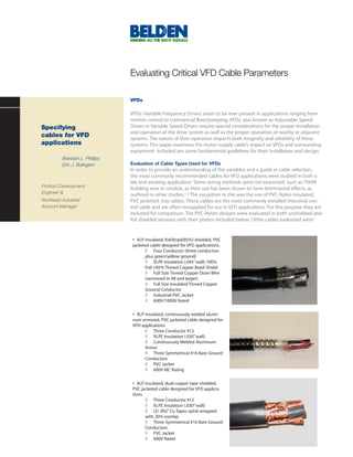
included for comparison. The PVC-Nylon designs were evaluated in both unshielded and
foil shielded versions with their photos included below. Other cables evaluated were:
• XLP insulated, foil/braid(85%) shielded, PVC
jacketed cable designed for VFD applications.
◊ Four Conductor (three conductors
plus green/yellow ground)
◊ XLPE Insulation (.045” wall) 100%
Foil +85% Tinned Copper Braid Shield
◊ Full Size Tinned Copper Drain Wire
(sectioned in #8 and larger)
◊ Full Size Insulated Tinned Copper
Ground Conductor
◊ Industrial PVC Jacket
◊ 600V/1000V Rated
• XLP insulated, continuously welded alumi-
num armored, PVC jacketed cable designed for
VFD applications
◊ Three Conductor #12
◊ XLPE Insulation (.030” wall)
◊ Continuously Welded Aluminum
Armor
◊ Three Symmetrical #16 Bare Ground
Conductors
◊ PVC Jacket
◊ 600V MC Rating
• XLP insulated, dual-copper tape shielded,
PVC jacketed cable designed for VFD applica-
tions
◊ Three Conductor #12
◊ XLPE Insulation (.030” wall)
◊ (2) .002” Cu Tapes spiral wrapped
with 20% overlap
◊ Three Symmetrical #16 Bare Ground
Conductors
◊ PVC Jacket
◊ 600V Rated
2. In addition to other benefits such as reduced
capacitance, more closely matching impedance
can improve motor life. Table 1 lists the
observed line-to-line peak motor terminal
voltages as well as the impedance of the
cables under test. The voltage measurements
were taken using 120ft cable lengths.
Table 1 lists typical impedance values for #12
AWG circuit conductors and is based on actual
data. Impedance is influenced by the geometry
and materials used in the manufacture of the
cable. The characteristic impedance of the
PVC-Nylon/PVC Foil Shield Type TC PVC-Nylon/PVC Type TC
cable is calculated using the following formula:
In order to better illustrate the application, Note that the cable impedance for 1HP
a schematic is included in Figure 1. The motor/drive combinations would need to
cables discussed are used to interconnect be roughly 1,000 ohms in order to match
the VFD to the AC motor(s). All testing was the corresponding motor’s impedance.
conducted using a current generation, A cable with such high characteristic Note the inversely proportional relationship
IGBT-based, 480V, 5HP, AC, VFD, a inverter- impedance would require conductor between the cable’s impedance and the peak
duty rated AC motor and relevant lab spacing in excess of several feet, implying motor terminal voltage. The cables with higher
equipment such as an LCR meter used to that such a cable would be both impractical impedance tended to result in lower peak
characterize the cables and an Oscilloscope and very expensive, if it were available. motor terminal voltages. The cable design for
used to make voltage measurements. impedance also impacts the cable’s useful life.
Lower voltages across the motor terminals also
translate into the cable being exposed to lower
voltages, increasing the life expectancy of the
cable. In addition, this reduces the likelihood
of reaching either the cable or motor’s CIV
(corona inception voltage). CIV is the point at
which the air gap between two conductors in
the cable or two windings on the motor breaks
down. If the CIV level is reached, insulation
failure can occur in the windings of the motor.3
Cable Design Impact on
Motor and Cable Life
Reflected waves caused by a cable-to-motor
impedance mismatch are prevalent in all AC
VFD applications. It is dependent on the length
of the cable, the rise-time of the PWM (Pulse
Width Modulated) carrier wave, the voltage of
the VFD, and the magnitude of the impedance
difference between the motor and cable.
Because cable length is mostly determined
by the application, the rise times vary by VFD
output semiconductor, and the voltage of the
VFD is driven by the application: the impedance
of the cable relative to the motor will be the
primary mechanism outlined in this paper.
First let’s look at estimated motor
impedance over a range of horsepower
ratings as indicated in Figure 2.
3. The corona discharge occurring between Cable Type Impedance (ohms) Voltage at Motor Terminals
conductors of the cable can reach very
high temperatures. If the insulation system Continuous Aluminum Armored Cable 87 1080 V
of the cable is a plastic material, such as
PVC, corona inception can cause premature Belden Foil/Braid VFD Cable 2950X Series 78 1110 V
failure due to a gradual localized melting
of the insulation. For this reason alone, Cu-Tape Shielded Belden VFD Cable 58 1150 V
thermoplastic insulations should not be used Un-Shielded PVC-Nyl/PVC 58 1150 V
for VFD applications. Thermoset insulation
systems such as XLP are ideal materials for Shielded PVC-Nyl/PVC 38 1260 V
such small localized temperature extremes
because of the high temperature stability Table 1. Impedance impact on motor terminal voltage, using 120 ft of cable
that they exhibit. The heat generated from
possible corona forms a thermally isolating
charred layer on the surface of the insulation radiate noise in excess of 80V to unshielded a non-metallic, vertical-tray flame rated fiber
preventing further degradation. All cables used communication wires/cables and in excess optic cable and media-converters or direct-
for VFDs should use a thermoset insulation of 10V to shielded instrumentation cables. connect fiber communication equipment for
system as a precautionary measure. Moreover, the use of unshielded cables in the instrumentation circuit. Other mitigation
conduits should be limited as the conduit is techniques may also be required, such as,
Understanding Radiated Noise an uncontrolled path to ground for the noise but not limited to, band-pass filters/chokes,
in VFD applications it captures. Any equipment in the vicinity output reactors, motor terminators, and
Radiated noise is proportional to the amount of the conduit or conduit hangers may be metallic barriers in cable trays or raceways.
of varying electric current within the VFD subject to an injection of this captured,
cable. As cable lengths grow, so does common-mode, noise. Therefore, unshielded Impact of Common Mode
the magnitude of reflected voltage. This cables in conduit are also not a recommended Noise in VFD Applications
transient over voltage combined with the method for connecting VFDs to motors. Noise radiating from the cable is one method
high amplitudes of current associated with for interference of adjacent systems, but is
VFDs creates a source of significant radiated If radiated noise is an issue in an existing often easier to identify and rectify. Common-
noise. By shielding the VFD cable, noise can VFD installation, care should be taken when mode noise is more difficult to diagnose as
be controlled. Relative shielding effectiveness routing instrumentation/control cables in the point of failure in adjacent systems, but it
was observed by noting the magnitude of the area. Maintain as much separation as is often the cause and most difficult situation
noise coupled to 10’ of parallel unshielded possible between instrumentation cables to rectify. High levels of noise across a broad
instrumentation cable for each VFD cable and VFD cables/leads. A minimum of one frequency range, often from 60Hz to 30MHz,
can capacitively couple from the windings
of the motor to the motor frame and then
to ground. Common-mode noise can also
capacitively couple from unshielded motor
leads in a conduit to ground via the conduit
ground straps, supports or other adjacent
and unintentional grounding paths. This
common-mode ground current is troublesome
because digital systems are susceptible to the
high-frequency noise generated by VFDs.
Components and systems susceptible to
common-mode noise are capacitive sensors
such as proximity sensors, thermocouples
signals, low-level communication signals,
and encoders. Because this noise takes
the path of least resistance, it finds
Figure 3. Noise coupled from VFD cables to unshielded instrumentation cable unpredictable grounding paths that change
and are often intermittent as humidity,
type. The results of the shielding effectiveness foot for shielded instrumentation and three temperature and load all change over time.
testing are documented in Figure 3: feet for unshielded instrumentation cables
As demonstrated by the pale green/blue is recommended. If the cables must cross One way to control common-mode noise
trace in Figure 3, foil shields are simply paths, try to minimize the amount of parallel is to provide a known path to ground for
not robust enough to capture the volume cable in the runs, preferably crossing the the noise captured at the motor’s frame.
of noise generated by VFDs. Unshielded instrument cable perpendicularly with the A low-impedance path, such as a properly
cables between VFDs and motors can power/VFD cable. If noise issues persist, use designed cable ground/shield system, can
provide this noise with an easier way to
4. get back to the drive, other than using the Conclusion shielding systems for VFD applications
building ground grid, steel, equipment, etc. Selecting an appropriate VFD cable can because of the low impedance path that they
improve overall drive system longevity provide for common-mode noise to return
Tests were conducted on the five cable types and reliability by mitigating the impact of to the drive. When VFD cables are installed in
to determine the ground path impedance reflected waves on the overall drive system. close proximity to low-level communications
of the shield and grounding system of Special attention should be paid to the cable’s cables and other susceptible devices, shielded
each cable. These tests were conducted insulation type, impedance, and shield/ground instrumentation cable should be used. It
across a broad frequency spectrum and system. Cables employing a heavy wall of would also be prudent to limit parallel runs
are outlined in Figure 4. Lower impedance thermoset insulation are recommended of VFD cable with instrumentation cables to
implies a more robust ground path and because of the proven electrical benefits and 10’ or less in order to reduce the likelihood
therefore relatively lower noise coupled to improved high temperature stability that they of experiencing radiated noise issues.
the building ground. Lower building ground exhibit. Shielding systems including: copper
noise means reduced troubleshooting of tape, combination foil/braid, and continuous
nearby adjacent systems and components. armoring types are the most appropriate
Figure 4. Shield/Ground impedance of the various cable types
1 E. J. Bartolucci, B.H. Finke, “Cable Design for PWM Variable Speed AC Drives”, IEEE Petroleum and Chemical Industry Conference, Sept, 1998
2 E. Bulington, S. Abney, G. Skibinski, “Cable Alternatives of PWM AC Drive Applications”, IEEE Petroleum and Chemical Industry Conference, Sept, 1999
3 Evon, S., Kempke, D., Saunders, L., Skibinski, G., “Riding the Reflected wave - IGBT Drive Technology Demands New Motor and Cable Considerations”,
IEEE Petroleum and Chemical Industry Conference, Sept, 1996