SlideShare a Scribd company logo
PCRED301002EN_Ver4.0.fm Page 1 Monday, November 22, 2004 2:10 PM


        Technical data sheet                                                 Electrical network protection
        2005
                                                                             Sepam series 40


                                                                             Sepam series 40 is a family of digital units used
                                                                             for current and voltage protection, in any medium
                                                                             or low voltage distribution system.

        Sepam series 40
                                                                   DE51020


        and its optional modules
         1 Base unit, with various User Machine
            Interface levels (UMI):
            b basic UMI
            b advanced UMI with graphical LCD screen.

         2 Remote advanced UMI.

         3 10 logic inputs and 8 output relays,
            4 outputs on the base unit + 1 optional
            module providing 10 inputs and 4 outputs.

         4 1 Modbus communication port:
            b direct connection to 2-wire RS 485,
            4-wire RS 485 and fibre optic networks
            b connection to Ethernet TCP/IP network
            via PowerLogic Ethernet server
            (Transparent Ready™).

         5 Processing of temperature data
            from 16 sensors, Pt100, Ni100, or Ni120.

         6 1 low level analogue output,
            0-10 mA, 4-20 mA or 0-20 mA.

         7 Software tools:
            b Sepam parameter and protection setting,
            control logic customisation
            b local installation operation
            b recovery and display of disturbance
            recording data.


        Characteristics                                                      Selection guide
         Conformity to standards                                             The Sepam series 40 family includes 7 types:
        IEC 60255 – Protection relays
        IEC 60529 – Degree of protection    IP52 on front panel              Specific            Applications
        IEC 60068 – Operating temperature   -25 ˚C to +70 ˚C                 protections         Substation   Transformer   Motor   Generator
         Certifications                                                      available
        e, UL508, CSA C22.2                                                                      S40          T40                   G40
         Auxiliary power supply                                              Directional earth   S41                        M41
        24-250 V DC and 110-240 V AC                                         fault
         Overall size of base units (H x W x D)                              Directional earth   S42          T42
        222 x 176 x 130 mm                                                   fault and phase
                                                                             overcurrent
PCRED301002EN_Ver4.0.fm Page 2 Monday, November 22, 2004 2:10 PM


             7 types of Sepam series 40
             b S40, S41, S42: substation incomers and              Protections                             ANSI code S40 S41 S42 T40 T42 M41 G40
                                                                   Phase overcurrent                       50/51         4     4     4     4    4     4     4
             feeders protection
                                                                   Voltage restrained overcurrent          50V/51V                                          1
             b T40, T42: transformer protection                    Earth fault,                            50N/51N       4     4     4     4    4     4     4
             b M41: motor protection                               sensitive earth fault                   50G/51G
                                                                   Breaker failure                         50BF          1     1     1     1    1     1     1
             b G40: generator protection.                          Unbalance/negative sequence             46            2     2     2     2    2     2     2
                                                                   Directional phase overcurrent           67                        2          2
                                                                   Directional earth fault                 67N/67NC            2     2          2     2
   DE51026


                                                                   Directional real overpower              32P                 1     1                1     1
                                                                   Directional reactive overpower          32Q/40                                     1     1
                                                                   Thermal overload                        49 RMS                          2    2     2     2
                                                                   Phase undercurrent                      37                                         1
                                                                   Locked rotor, excessive starting time   48/51LR/14                                 1
                                                                   Starts per hour                         66                                         1
                                                                   Positive sequence undervoltage          27D                                        2
                                                                   Remanent undervoltage                   27R                                        1
                                                                   Undervoltage                            27/27S        2     2     2     2    2     2     2
                                                                   Overvoltage                             59            2     2     2     2    2     2     2
                                                                   Neutral voltage displacement            59N           2     2     2     2    2     2     2
                                                                   Negative sequence overvoltage           47            1     1     1     1    1     1     1
                                                                   Overfrequency                           81H           2     2     2     2    2     2     2
                                                                   Underfrequency                          81L           4     4     4     4    4     4     4
                                                                   Recloser (4 cycles)                     79            v     v     v
                                                                   Temperature monitoring                  38/49T                          v    v     v     v
                                                                   (8 or 16 RTDs, 2 set points per RTD)
                                                                   Thermostat / Buchholz                   26/63                           v    v
                                                                   Metering
                                                                   RMS phase current I1,I2,I3, residual current I0       b     b     b     b    b     b     b
                                                                   Average current I1, I2, I3                            b     b     b     b    b     b     b
                                                                   Peak demand current IM1, IM2, IM3
                                                                   Voltage U21, U32, U13, V1, V2, V3                     b     b     b     b    b     b     b
                                                                   Residual voltage V0
                                                                   Positive sequence voltage Vd / rotation direction,    b     b     b     b    b     b     b
                                                                   Negative sequence voltage Vi
                                                                   Frequency                                             b     b     b     b    b     b     b
                                                                   Real / reactive / apparent power P, Q, S              b     b     b     b    b     b     b
                                                                   Peak demand real/reactive power PM, QM
             Sepam series 40 connection scheme.                    Power factor
                                                                   Calculated real / reactive energy (±W.h, ±var.h)      b     b     b     b    b     b     b
                                                                   Real/reactive energy impulse counter (±W.h, ±var.h)   v     v     v     v    v     v     v
                                                                   Temperature                                                             v    v     v     v
   DE50472


                                                                   Network and machine diagnosis
                                                                   Tripping current TripI1, TripI2, TripI3, TripI0       b     b     b     b    b     b     b
                                                                   Tripping context                                      b     b     b     b    b     b     b
                                                                   Unbalance ratio/negative sequence current             b     b     b     b    b     b     b
                                                                   Phase shift ϕ0, ϕ1, ϕ2, ϕ3                            b     b     b     b    b     b     b
                                                                   Disturbance recording                                 b     b     b     b    b     b     b
                                                                   Thermal capacity used                                                   b    b     b     b
                                                                   Remaining operating time before overload tripping                       b    b     b     b
                                                                   Waiting time after overload tripping                                    b    b     b     b
                                                                   Running hours counter / operating time                                  b    b     b     b
                                                                   Starting current and time                                                          b
                                                                   Start inhibit time delay, number of starts                                         b
                                                                   before inhibition
                                                                   Switchgear diagnosis
                                                                   Cumulative breaking current                           b     b     b     b    b     b     b
                                                                   Trip circuit supervision                              v     v     v     v    v     v     v
                                                                   Number of operations, operating time, charging time   v     v     v     v    v     v     v
                                                                   CT/VT supervision                                     b     b     b     b    b     b     b
                                                                   Control and monitoring                  ANSI code
                                                                   Circuit breaker / contactor control     94/69         b     b     b     b    b     b     b
             Sepam series 40 rear face:                            Latching / acknowledgment               86            b     b     b     b    b     b     b
             1 Base unit.                                          Logic discrimination                    68            v     v     v     v    v     v     v
                                                                   Switching of group of settings                        b     b     b     b    b     b     b
             A Main connector.
                                                                   Annunciation                            30            b     b     b     b    b     b     b
             B Input current connector.                            Logical equation editor                               b     b     b     b    b     b     b
             C Modbus communication port.                          Modbus communication
                                                                   Measurement readout                                    v    v    v      v    v     v     v
             D Link to remote optional modules.
                                                                   Remote indication and time tagging of event            v    v    v      v    v     v     v
             E Input voltage connector.                            Remote control orders                                  v    v    v      v    v     v     v
             2 Optional module, 10 inputs and 4 outputs.           Remote setting of protections                          v    v    v      v    v     v     v
                                                                   Transfer of disturbance recording data                 v    v    v      v    v     v     v
                                                                   b standard, v according to parameter settings and optional modules.


             Schneider Electric Ltd
             123 Jack Lane                                         As standards, specifications and designs change from time to time, please ask for confirmation
             Leeds                                                 of the information given in this publication.
             LS10 1BS
             Tel: 0870 608 8 608
             Fax: 0870 608 8 606

             http://www.schneider.co.uk

             MGMV 5659                                                                                                                                    DEC 04

More Related Content

What's hot

Open Hardware: Arduino #barcampmexico
Open Hardware: Arduino #barcampmexicoOpen Hardware: Arduino #barcampmexico
Open Hardware: Arduino #barcampmexico
Gonzalo Maldonado
 
3000 001
3000 0013000 001
3000 001
chaitannya
 
DS25CP102 (English)
DS25CP102 (English)DS25CP102 (English)
DS25CP102 (English)
Tsuyoshi Horigome
 
H355
H355H355
Advanced motion controls_azbdc40a8
Advanced motion controls_azbdc40a8Advanced motion controls_azbdc40a8
Advanced motion controls_azbdc40a8
Electromate
 
Sicop datasheet
Sicop datasheetSicop datasheet
Sicop datasheet
angelochintu
 
D1 be29c1d01
D1 be29c1d01D1 be29c1d01
D1 be29c1d01
malae
 
Vertx v200 ds_en
Vertx v200 ds_enVertx v200 ds_en
Vertx v200 ds_en
sanzen enterprises
 
Tda8511 j
Tda8511 jTda8511 j
3 vt 1..5
3 vt 1..53 vt 1..5
3 vt 1..5
angelochintu
 
01. superswitch switch disconnector fuse and din bs fuses
01. superswitch switch disconnector fuse and din bs fuses01. superswitch switch disconnector fuse and din bs fuses
01. superswitch switch disconnector fuse and din bs fuses
angelochintu
 
7000 001
7000 0017000 001
7000 001
chaitannya
 
Advanced motion controls azbe12a8
Advanced motion controls azbe12a8Advanced motion controls azbe12a8
Advanced motion controls azbe12a8
Electromate
 
Gs jd-200
Gs jd-200Gs jd-200
Gs jd-200
jlbn24
 
Sca1000 Fm A0%200 As
Sca1000 Fm A0%200 AsSca1000 Fm A0%200 As
Sca1000 Fm A0%200 As
guest987902e
 
Advanced motion controls azbdc40a8
Advanced motion controls azbdc40a8Advanced motion controls azbdc40a8
Advanced motion controls azbdc40a8
Electromate
 
P89 lpc920 921_922_9221
P89 lpc920 921_922_9221P89 lpc920 921_922_9221
P89 lpc920 921_922_9221
trieuvantam
 
Long-term stability of an SiGeHBT-based active cold load.pdf
Long-term stability of an SiGeHBT-based active cold load.pdfLong-term stability of an SiGeHBT-based active cold load.pdf
Long-term stability of an SiGeHBT-based active cold load.pdf
grssieee
 
Advanced motion controls azbe6a8
Advanced motion controls azbe6a8Advanced motion controls azbe6a8
Advanced motion controls azbe6a8
Electromate
 
Datasheet
DatasheetDatasheet
Datasheet
marnotorious
 

What's hot (20)

Open Hardware: Arduino #barcampmexico
Open Hardware: Arduino #barcampmexicoOpen Hardware: Arduino #barcampmexico
Open Hardware: Arduino #barcampmexico
 
3000 001
3000 0013000 001
3000 001
 
DS25CP102 (English)
DS25CP102 (English)DS25CP102 (English)
DS25CP102 (English)
 
H355
H355H355
H355
 
Advanced motion controls_azbdc40a8
Advanced motion controls_azbdc40a8Advanced motion controls_azbdc40a8
Advanced motion controls_azbdc40a8
 
Sicop datasheet
Sicop datasheetSicop datasheet
Sicop datasheet
 
D1 be29c1d01
D1 be29c1d01D1 be29c1d01
D1 be29c1d01
 
Vertx v200 ds_en
Vertx v200 ds_enVertx v200 ds_en
Vertx v200 ds_en
 
Tda8511 j
Tda8511 jTda8511 j
Tda8511 j
 
3 vt 1..5
3 vt 1..53 vt 1..5
3 vt 1..5
 
01. superswitch switch disconnector fuse and din bs fuses
01. superswitch switch disconnector fuse and din bs fuses01. superswitch switch disconnector fuse and din bs fuses
01. superswitch switch disconnector fuse and din bs fuses
 
7000 001
7000 0017000 001
7000 001
 
Advanced motion controls azbe12a8
Advanced motion controls azbe12a8Advanced motion controls azbe12a8
Advanced motion controls azbe12a8
 
Gs jd-200
Gs jd-200Gs jd-200
Gs jd-200
 
Sca1000 Fm A0%200 As
Sca1000 Fm A0%200 AsSca1000 Fm A0%200 As
Sca1000 Fm A0%200 As
 
Advanced motion controls azbdc40a8
Advanced motion controls azbdc40a8Advanced motion controls azbdc40a8
Advanced motion controls azbdc40a8
 
P89 lpc920 921_922_9221
P89 lpc920 921_922_9221P89 lpc920 921_922_9221
P89 lpc920 921_922_9221
 
Long-term stability of an SiGeHBT-based active cold load.pdf
Long-term stability of an SiGeHBT-based active cold load.pdfLong-term stability of an SiGeHBT-based active cold load.pdf
Long-term stability of an SiGeHBT-based active cold load.pdf
 
Advanced motion controls azbe6a8
Advanced motion controls azbe6a8Advanced motion controls azbe6a8
Advanced motion controls azbe6a8
 
Datasheet
DatasheetDatasheet
Datasheet
 

Similar to 2 page s40 data sheet

デザインキット・擬似共振回路のインデックス
デザインキット・擬似共振回路のインデックスデザインキット・擬似共振回路のインデックス
デザインキット・擬似共振回路のインデックス
Tsuyoshi Horigome
 
Lsa47.2
Lsa47.2Lsa47.2
電流臨界モード方式PFC制御回路の解説書
電流臨界モード方式PFC制御回路の解説書電流臨界モード方式PFC制御回路の解説書
電流臨界モード方式PFC制御回路の解説書
Tsuyoshi Horigome
 
Generator protection gers
Generator protection gersGenerator protection gers
Generator protection gers
Habudin Hassan
 
デザインキット・マイクロコントローラ(U pc494)による降圧回路のインデックス
デザインキット・マイクロコントローラ(U pc494)による降圧回路のインデックスデザインキット・マイクロコントローラ(U pc494)による降圧回路のインデックス
デザインキット・マイクロコントローラ(U pc494)による降圧回路のインデックス
Tsuyoshi Horigome
 
Basic protection and relaying
Basic protection and relayingBasic protection and relaying
Basic protection and relaying
Biswajit Pratihari
 
Sicop datasheet
Sicop datasheetSicop datasheet
Sicop datasheet
angeloneha
 
Ppt 2
Ppt 2Ppt 2
Ppt 2
JM_IEEE
 
SL_VM1(EN)C_1VCP000238-1001.ppt
SL_VM1(EN)C_1VCP000238-1001.pptSL_VM1(EN)C_1VCP000238-1001.ppt
SL_VM1(EN)C_1VCP000238-1001.ppt
VikashKumarPrasad4
 
Dc mini-breaker
Dc mini-breakerDc mini-breaker
Dc mini-breaker
Jiandong Wu
 
LMV221 sdx
LMV221 sdxLMV221 sdx
LMV221 sdx
whatry1995
 
Specifications
SpecificationsSpecifications
Specifications
Surendra Kumar Sharma
 
7SR110 Argus Relay
7SR110 Argus Relay7SR110 Argus Relay
7SR110 Argus Relay
ashwini reliserv
 
2 n2222
2 n22222 n2222
2 n2222
2 n22222 n2222
2 n2222
Maya Azteca
 
2N2222のデータシート
2N2222のデータシート2N2222のデータシート
2N2222のデータシート
Tsuyoshi Horigome
 
33/11 kV substation (u.p.p.c.l.)
33/11 kV substation (u.p.p.c.l.)33/11 kV substation (u.p.p.c.l.)
33/11 kV substation (u.p.p.c.l.)
Prateek Agarwal
 
LM324 Low Power Quad Op Amps
LM324 Low Power Quad Op AmpsLM324 Low Power Quad Op Amps
LM324 Low Power Quad Op Amps
Yong Heui Cho
 
1 n4148 1n4448
1 n4148 1n44481 n4148 1n4448
1 n4148 1n4448
Rendy Ardiwinata
 
Bf422
Bf422Bf422
Bf422
nicodelga
 

Similar to 2 page s40 data sheet (20)

デザインキット・擬似共振回路のインデックス
デザインキット・擬似共振回路のインデックスデザインキット・擬似共振回路のインデックス
デザインキット・擬似共振回路のインデックス
 
Lsa47.2
Lsa47.2Lsa47.2
Lsa47.2
 
電流臨界モード方式PFC制御回路の解説書
電流臨界モード方式PFC制御回路の解説書電流臨界モード方式PFC制御回路の解説書
電流臨界モード方式PFC制御回路の解説書
 
Generator protection gers
Generator protection gersGenerator protection gers
Generator protection gers
 
デザインキット・マイクロコントローラ(U pc494)による降圧回路のインデックス
デザインキット・マイクロコントローラ(U pc494)による降圧回路のインデックスデザインキット・マイクロコントローラ(U pc494)による降圧回路のインデックス
デザインキット・マイクロコントローラ(U pc494)による降圧回路のインデックス
 
Basic protection and relaying
Basic protection and relayingBasic protection and relaying
Basic protection and relaying
 
Sicop datasheet
Sicop datasheetSicop datasheet
Sicop datasheet
 
Ppt 2
Ppt 2Ppt 2
Ppt 2
 
SL_VM1(EN)C_1VCP000238-1001.ppt
SL_VM1(EN)C_1VCP000238-1001.pptSL_VM1(EN)C_1VCP000238-1001.ppt
SL_VM1(EN)C_1VCP000238-1001.ppt
 
Dc mini-breaker
Dc mini-breakerDc mini-breaker
Dc mini-breaker
 
LMV221 sdx
LMV221 sdxLMV221 sdx
LMV221 sdx
 
Specifications
SpecificationsSpecifications
Specifications
 
7SR110 Argus Relay
7SR110 Argus Relay7SR110 Argus Relay
7SR110 Argus Relay
 
2 n2222
2 n22222 n2222
2 n2222
 
2 n2222
2 n22222 n2222
2 n2222
 
2N2222のデータシート
2N2222のデータシート2N2222のデータシート
2N2222のデータシート
 
33/11 kV substation (u.p.p.c.l.)
33/11 kV substation (u.p.p.c.l.)33/11 kV substation (u.p.p.c.l.)
33/11 kV substation (u.p.p.c.l.)
 
LM324 Low Power Quad Op Amps
LM324 Low Power Quad Op AmpsLM324 Low Power Quad Op Amps
LM324 Low Power Quad Op Amps
 
1 n4148 1n4448
1 n4148 1n44481 n4148 1n4448
1 n4148 1n4448
 
Bf422
Bf422Bf422
Bf422
 

2 page s40 data sheet

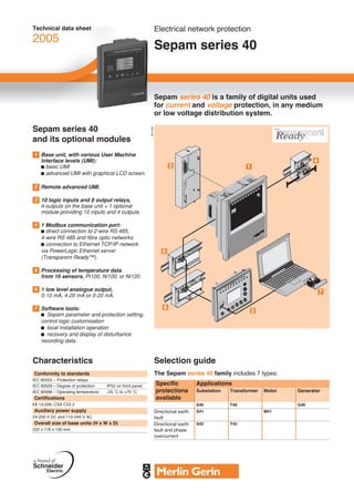
  • 1. PCRED301002EN_Ver4.0.fm Page 1 Monday, November 22, 2004 2:10 PM Technical data sheet Electrical network protection 2005 Sepam series 40 Sepam series 40 is a family of digital units used for current and voltage protection, in any medium or low voltage distribution system. Sepam series 40 DE51020 and its optional modules 1 Base unit, with various User Machine Interface levels (UMI): b basic UMI b advanced UMI with graphical LCD screen. 2 Remote advanced UMI. 3 10 logic inputs and 8 output relays, 4 outputs on the base unit + 1 optional module providing 10 inputs and 4 outputs. 4 1 Modbus communication port: b direct connection to 2-wire RS 485, 4-wire RS 485 and fibre optic networks b connection to Ethernet TCP/IP network via PowerLogic Ethernet server (Transparent Ready™). 5 Processing of temperature data from 16 sensors, Pt100, Ni100, or Ni120. 6 1 low level analogue output, 0-10 mA, 4-20 mA or 0-20 mA. 7 Software tools: b Sepam parameter and protection setting, control logic customisation b local installation operation b recovery and display of disturbance recording data. Characteristics Selection guide Conformity to standards The Sepam series 40 family includes 7 types: IEC 60255 – Protection relays IEC 60529 – Degree of protection IP52 on front panel Specific Applications IEC 60068 – Operating temperature -25 ˚C to +70 ˚C protections Substation Transformer Motor Generator Certifications available e, UL508, CSA C22.2 S40 T40 G40 Auxiliary power supply Directional earth S41 M41 24-250 V DC and 110-240 V AC fault Overall size of base units (H x W x D) Directional earth S42 T42 222 x 176 x 130 mm fault and phase overcurrent
  • 2. PCRED301002EN_Ver4.0.fm Page 2 Monday, November 22, 2004 2:10 PM 7 types of Sepam series 40 b S40, S41, S42: substation incomers and Protections ANSI code S40 S41 S42 T40 T42 M41 G40 Phase overcurrent 50/51 4 4 4 4 4 4 4 feeders protection Voltage restrained overcurrent 50V/51V 1 b T40, T42: transformer protection Earth fault, 50N/51N 4 4 4 4 4 4 4 b M41: motor protection sensitive earth fault 50G/51G Breaker failure 50BF 1 1 1 1 1 1 1 b G40: generator protection. Unbalance/negative sequence 46 2 2 2 2 2 2 2 Directional phase overcurrent 67 2 2 Directional earth fault 67N/67NC 2 2 2 2 DE51026 Directional real overpower 32P 1 1 1 1 Directional reactive overpower 32Q/40 1 1 Thermal overload 49 RMS 2 2 2 2 Phase undercurrent 37 1 Locked rotor, excessive starting time 48/51LR/14 1 Starts per hour 66 1 Positive sequence undervoltage 27D 2 Remanent undervoltage 27R 1 Undervoltage 27/27S 2 2 2 2 2 2 2 Overvoltage 59 2 2 2 2 2 2 2 Neutral voltage displacement 59N 2 2 2 2 2 2 2 Negative sequence overvoltage 47 1 1 1 1 1 1 1 Overfrequency 81H 2 2 2 2 2 2 2 Underfrequency 81L 4 4 4 4 4 4 4 Recloser (4 cycles) 79 v v v Temperature monitoring 38/49T v v v v (8 or 16 RTDs, 2 set points per RTD) Thermostat / Buchholz 26/63 v v Metering RMS phase current I1,I2,I3, residual current I0 b b b b b b b Average current I1, I2, I3 b b b b b b b Peak demand current IM1, IM2, IM3 Voltage U21, U32, U13, V1, V2, V3 b b b b b b b Residual voltage V0 Positive sequence voltage Vd / rotation direction, b b b b b b b Negative sequence voltage Vi Frequency b b b b b b b Real / reactive / apparent power P, Q, S b b b b b b b Peak demand real/reactive power PM, QM Sepam series 40 connection scheme. Power factor Calculated real / reactive energy (±W.h, ±var.h) b b b b b b b Real/reactive energy impulse counter (±W.h, ±var.h) v v v v v v v Temperature v v v v DE50472 Network and machine diagnosis Tripping current TripI1, TripI2, TripI3, TripI0 b b b b b b b Tripping context b b b b b b b Unbalance ratio/negative sequence current b b b b b b b Phase shift ϕ0, ϕ1, ϕ2, ϕ3 b b b b b b b Disturbance recording b b b b b b b Thermal capacity used b b b b Remaining operating time before overload tripping b b b b Waiting time after overload tripping b b b b Running hours counter / operating time b b b b Starting current and time b Start inhibit time delay, number of starts b before inhibition Switchgear diagnosis Cumulative breaking current b b b b b b b Trip circuit supervision v v v v v v v Number of operations, operating time, charging time v v v v v v v CT/VT supervision b b b b b b b Control and monitoring ANSI code Circuit breaker / contactor control 94/69 b b b b b b b Sepam series 40 rear face: Latching / acknowledgment 86 b b b b b b b 1 Base unit. Logic discrimination 68 v v v v v v v Switching of group of settings b b b b b b b A Main connector. Annunciation 30 b b b b b b b B Input current connector. Logical equation editor b b b b b b b C Modbus communication port. Modbus communication Measurement readout v v v v v v v D Link to remote optional modules. Remote indication and time tagging of event v v v v v v v E Input voltage connector. Remote control orders v v v v v v v 2 Optional module, 10 inputs and 4 outputs. Remote setting of protections v v v v v v v Transfer of disturbance recording data v v v v v v v b standard, v according to parameter settings and optional modules. Schneider Electric Ltd 123 Jack Lane As standards, specifications and designs change from time to time, please ask for confirmation Leeds of the information given in this publication. LS10 1BS Tel: 0870 608 8 608 Fax: 0870 608 8 606 http://www.schneider.co.uk MGMV 5659 DEC 04