This document provides an introduction and overview of a project that utilizes solar energy for smart street lighting. The project aims to make livelihoods more eco-friendly by using solar energy to power street lights in a way that controls their intensity based on sunlight levels throughout the day. Solar panels convert sunlight to electricity that is stored in batteries and used to power the street lights. The system is designed to dim the lights at dawn and dusk and turn them off at night, reducing energy consumption. The document discusses the motivation behind using renewable solar energy over fossil fuels to power street lights and provides an organization of the thesis and details on the project.
Solar energy is energy from the sun that can be converted into useful forms of energy, such as heat, light, and electricity. Solar energy originates from thermonuclear fusion reactions on the sun. It consists of radiant light and heat from the sun that is harnessed using a variety of ever-improving technologies such as solar heating systems, photovoltaics, and solar thermal energy. While solar energy has disadvantages related to cost, location, reliability, and inefficiency, it is a renewable source that can help reduce dependence on non-renewable energy sources if adopted more widely.
Solar trackers orient solar panels towards the sun using light sensors and motors. There are two main types: single-axis trackers rotate around one axis, while dual-axis trackers rotate around two axes for maximum sun exposure. Trackers increase solar panel output by approximately 40% compared to fixed panels. They work by measuring light intensity with sensors to determine the sun's position and adjusting the panel orientation accordingly through active control systems. Open loop trackers use computer algorithms and timing systems rather than sensors. Solar trackers improve efficiency and power generation from solar installations.
Oro551 res - unit 1 - the solar constantkarthi keyan
This document discusses principles of solar radiation. It covers the role of solar energy, environmental impacts, physics of the sun, and measurements of solar radiation. Specifically, it defines the solar constant as the rate at which solar energy arrives at the top of the atmosphere, which is approximately 1.367 kW/m2. It also provides equivalent units of the solar constant in kcal/m2/hr and Btu/ft2/hr.
This document provides guidelines for a solar PV system. It discusses the components of the system including solar panels, batteries, charge controllers, inverters and meters. Solar panels convert sunlight to electricity while batteries store it for use when sunlight is unavailable. Charge controllers regulate battery charging and inverters convert DC to AC current. Meters track energy exchange with the grid through net metering. The document also covers topics like types of solar panels and batteries, system installation, maintenance, sizing considerations and mounting options.
This ppt explained on LED based street lights with auto intensity control using solar power from photovoltaic cells and Photovoltaic panels are used for charging batteries by converting the sunlight into electricity
This document provides an introduction to solar radiation and its role in powering the water cycle. It discusses the composition and structure of the Sun, and how it produces radiation through nuclear fusion. While solar radiation is generally constant, it exhibits variations in the form of solar spots and an 11-year activity cycle. The amount of radiation emitted by any body is determined by the Stefan-Boltzmann law, which relates radiation to the body's temperature and emissivity.
The document discusses how solar panels work to convert sunlight into electrical energy. It begins with an introduction to the sun and how its energy impacts Earth. It then explains that solar panels use silicon photovoltaic cells that directly convert sunlight into electricity through a process where photons dislodge electrons from silicon atoms, generating a flow of electricity. The document concludes by discussing how solar energy can be stored in batteries and used to power individual homes and large solar power plants.
ORO551 RES - Unit 1 - Role and potential of new and renewable sourcekarthi keyan
This document outlines the syllabus for a course on renewable energy sources. It includes 5 units that cover various renewable technologies like solar, wind, geothermal, and biomass. Unit 1 discusses the principles of solar radiation and its environmental impacts. Unit 2 covers methods of collecting and storing solar energy. Unit 3 explores applications of solar energy. Later units address wind energy, biomass, and other sources like geothermal and tidal energies. The course objectives and outcomes for each unit are provided along with textbook references and an overview of the course content.
- Solar power involves converting sunlight into electricity through photovoltaic cells or concentrated solar power.
- Pakistan receives high solar radiation throughout the year, especially in remote areas not connected to the national power grid, making solar power feasible.
- Advantages of solar power in Pakistan include a free power source, no pollution, and suitability for remote areas, while disadvantages are high initial costs and reliance on sunlight.
- Several solar power plants currently operate in Pakistan and the government is promoting expansion through land allocation projects.
Solar energy is radiant light and heat from the Sun that is harnessed using a range of ever-evolving technologies such as solar heating, photovoltaics, solar thermal energy, solar architecture, molten salt power plants and artificial photosynthesis.
This document provides an overview of fundamentals of solar PV systems. It discusses solar energy basics and the solar spectrum. It describes the construction and working principle of photovoltaic cells made of semiconductors like silicon. The document outlines different types of solar PV technologies like monocrystalline, polycrystalline and thin film solar cells. It also discusses designing of solar PV systems including components like blocking diodes and bypass diodes. The advantages and disadvantages of solar energy systems are highlighted.
An irrigation controller is an essential tool for applying water efficiently and at the right time. Controllers have evolved from mechanical timers to complex computer-based systems that can accurately control water, energy, and chemicals in response to environmental changes. There are two main types of controllers: open loop systems that apply preset actions, and closed loop systems that use feedback from sensors to make decisions and apply them to the irrigation system.
Solar energy can be harnessed using a range of technologies to capture and convert sunlight into useful forms of energy. There are two main types of solar energy technologies - passive solar, which uses sunlight without active solar components, and active solar, which uses electro-mechanical devices to convert sunlight into electricity or to power machinery. Solar energy can be used for heating, cooling, power generation, and other applications by using technologies like solar thermal collectors and photovoltaic panels. The amount of solar energy reaching the Earth's surface depends on geographic factors like latitude and weather conditions.
This document contains FAQs (Frequently Asked Questions) on solar inverters. The reader will get a very good idea about solar inverters, the different types, and where they are used.
The document discusses solar powered irrigation systems. It begins with an introduction to solar power and its potential. It then discusses the components of photovoltaic systems and different types of solar irrigation systems, including surface pumps, submersible pumps, and automated irrigation systems using sensors. Economics of solar pumps are presented, showing they have lower operating costs and higher return on investment than diesel pumps. The conclusion emphasizes that solar irrigation systems provide flexible, low-cost, and environmentally friendly water solutions.
NTPC has potential to develop roof-top solar power on its buildings and townships. India has ambitious renewable energy targets of 175 GW by 2022, up from the current 19.5 GW of solar installed. Roof-top solar is promising for NTPC as it does not require additional land, has lower transmission losses, and provides opportunities to supply surplus power to the grid or charge electric vehicles. NTPC should leverage its assets and expertise to capture more of India's fast growing renewable energy market.
This document discusses the design and components of a solar tracking system. It describes how single-axis and dual-axis trackers work to follow the sun's movement and maximize solar panel efficiency. The system uses light dependent resistors to sense the sun's position and a microcontroller to command stepper motors that adjust the panel orientation accordingly. It aims to automatically point the solar panel towards the sun to produce the most electricity from sunlight.
The document provides an introduction to solar energy, including:
- The sun produces enormous amounts of energy that can be harnessed using solar panels to generate electricity. On average, every square meter of the Earth's surface receives 164 watts of solar energy from the sun.
- Solar energy refers to the energy from the sun, which has produced energy for billions of years and is a renewable source of energy unlike fossil fuels. It is one of the cleanest sources of energy since it does not produce pollutants.
- Solar cells, also called photovoltaic cells, are electronic devices that convert sunlight directly into electricity and are used in solar modules and panels to harness solar energy for applications like powering homes
This document summarizes information about solar power plants. It discusses how solar power plants work by converting sunlight to electricity through either photovoltaic cells or concentrated solar power. It provides a diagram of a solar power plant and lists its key components like solar modules, controllers, batteries, and inverters. Standalone and grid-tie solar systems are described. Advantages of solar energy include being clean, renewable and producing power with little maintenance, though high upfront costs are a disadvantage. India's largest solar plants are noted. Uses of solar energy include water pumps, buildings, remote areas, and more.
Dual axis solar tracking system using microcontrollerPrathima Prathu
This document describes a dual axis solar tracking system that uses a microcontroller. It aims to utilize maximum solar energy by using a solar panel that tracks the sun's position with help from light detecting resistors and a microcontroller. This is more efficient than stationary panels as it allows the panel to remain perpendicular to the incoming solar energy. The system has higher energy output and flexibility than single axis trackers while being more eco-friendly. It could help reduce energy crisis issues by optimizing solar energy collection.
The document discusses solar off-grid systems, which convert sunlight into electricity without being connected to an electrical grid. They are useful for powering areas with little grid access. Solar off-grid systems consist of solar panels that absorb sunlight, batteries that store the generated current, a controller that regulates the battery charging, and an inverter that converts DC to AC current. They have advantages like being renewable, reducing emissions, and saving on electricity bills. Major applications include household power backup, medical clinics, telecom stations, and defense and remote weather stations. The document also describes Medors Renewable Energy, a leading Indian manufacturer of high-quality solar panels and off-grid systems.
Android mobile charger using solar panelArun Prasath
This document presents the design of an Android mobile charger using a solar panel. It introduces the need for portable chargers for mobile devices and explains how solar energy can be harnessed to power such a charger. Key aspects of the design include using a solar panel to convert sunlight into electrical energy, which is then stored in rechargeable batteries. The stored energy can then be used to recharge mobile devices. The summary concludes that such solar-powered chargers can help reduce energy consumption from non-renewable sources and promote sustainable energy solutions.
This document discusses solar energy and solar power plants. It describes how solar radiation is harnessed using technologies like solar heating and photovoltaics. A basic solar power plant has solar collectors that concentrate sunlight, a butane boiler that generates steam using the heated water from collectors, a turbine turned by the steam to generate electricity, and a condenser to cool the steam. Solar energy can be used for applications like water pumping, heating, drying, and power generation. It has advantages of being renewable and pollution-free but is only intermittently available.
Energy Conservation is become a necessity for the future of mankind. Energy resources are depleting on a large scale so renewable resources of energy like solar energy and wind energy are used to convert into the necessary forms of energy.
This document summarizes a seminar on solar powered water pumping systems presented by Rahul Rao MJ. It introduces the basic components of solar water pumping systems including solar modules made of photovoltaic panels that produce direct current to run water pumps. There are two main types of systems - battery coupled systems that store solar energy in batteries to power pumps day or night, and direct coupled systems that power pumps directly from solar panels during the day. Key factors in selecting a system include water needs, costs, and maximizing solar energy collection through proper site selection and panel orientation. Solar water pumping provides environmental and economic benefits for applications like agriculture, remote homes, and developing communities.
This document discusses single axis solar tracking systems. It begins with an introduction that outlines the increasing demand for renewable energy and potential of solar energy. It then describes the concept of a single axis solar tracking system which uses a tilted solar panel mount and motor to move the panel relative to the sun's position. The document goes on to describe different types of single axis trackers and discuss sun-earth angles and how they vary throughout the year. It also includes calculations of incidence angles for different periods in Warangal, India. Finally, it discusses the future of solar tracking and double axis tracking systems.
This document summarizes a seminar on basic design principles and components of solar photovoltaic systems. It discusses:
1) How solar photovoltaic systems work by converting sunlight directly into electricity using the photovoltaic effect in solar cells.
2) The basic components of solar photovoltaic systems including solar modules made of connected solar cells, inverters, batteries for storage, and electrical loads.
3) Applications of solar photovoltaic technology including water pumping, commercial and residential power, consumer electronics, and telecommunications.
4) The current state and future potential of solar photovoltaic installations in India, which has significant solar resources and a growing domestic manufacturing industry.
Solar street lighting system should be implemented everywhere to decrease the 40% energy demand in highways we are using here both conventional energy and solar energy for reliability purpose
Automatic street light control using LDR.Fazlur Rahman
The document is a project report submitted by Md. Fazlur Rahman to Eastern University of Bangladesh that details an automatic street light control system using a light dependent resistor. The system aims to automatically control street lights based on changes in light intensity by using an LDR to detect light levels and a triac controlled circuit to adjust the intensity of the street lights accordingly. The project report includes sections on the objectives, components, theory of operation using a microcontroller, thyristor, optocoupler and circuit design.
Solar powered LED street light with automated power supply systemSangeeth Soman
The document describes a project report for a solar powered LED street light with an automated power supply system. It was submitted by 4 students to fulfill their Bachelor of Engineering degree requirements. The project involves designing a street light system that uses solar panels to charge a battery during the day. An inverter converts the DC battery power to AC to power the LED lamp. A switching circuit uses a light sensor to automatically turn the lamp on when it gets dark and off when it's light out. An AC backup supply is also provided to charge the battery if the solar power is insufficient.
Final project report on Solar street light Darshil Shah
The document describes a project report for a solar powered LED street light with automatic intensity control. It includes a functional block diagram and explanations of the components, including a solar panel, charge controller circuit, rechargeable battery, voltage divider circuit, and Arduino UNO microcontroller. It also covers the software implementation through simulations of the charge controller and voltage divider circuits. The coding for the real time clock and PWM in Arduino is shown. The hardware implementation, operation, and testing are described as well. Intensity levels are controlled at different times of day and night based on readings from the real time clock.
Project details - I have made a project Dual Axis Solar Tracker using Arduino to align the solar panel towards the higher density of Sun light. I have used a ATMEGA168 controller IC for programming, and two servo motor for movement of solar panel. It was now also available on EngineersGarage with the link- http://www.engineersgarage.com/contribution/how-to-make-a-solar-tracker. Check this out.
This document provides a draft report on the Solar Sailor Interactive Educational Game project. It includes sections on the project requirements, product overview, how to play the game, interface, acceptance checklist, safety concerns, components and connections, and high level block diagram. The game is intended to educate children on solar energy and sails through an interactive play experience. An 8 person team from Colorado Technical University designed and developed the game over several revisions.
This document is a project report on the enhancement of a solar tracking system submitted in partial fulfillment of a Bachelor of Engineering degree. It includes an introduction outlining the project, a review of the project objectives, the evolution of solar trackers, and descriptions of the key system components and design considerations for the solar tracking system. The report covers types of solar trackers, the sun's apparent motion, specifications of the parts used, assembly techniques, working principles, programming, analysis, and conclusions. The project aims to develop an automatic solar tracking system to keep solar panels aligned with the sun to maximize energy production.
This document is a project report on the design and implementation of a solar tracker system using a microcontroller. It includes an introduction outlining the need for renewable energy sources like solar power. The objectives are to design a system to track solar UV light for solar panels and accurately measure the sun's altitude angle from sunrise to sunset. The literature review covers types of solar trackers including single-axis and dual-axis systems. It also discusses active and passive solar tracking methods and reviews concepts like solar irradiation and efficiency of fixed and tracking solar collectors. Block diagrams, flow charts and the methodology are discussed in subsequent chapters.
RE Energen is a renewable energy company based in India that was established in 2015. It focuses on solar energy, LED lighting, and energy management solutions. The company was founded by two entrepreneurs interested in sustainable businesses that protect the environment. RE Energen aims to be a leader in solar energy and provide high quality customer service. It offers solar street lights powered by photovoltaic panels in various wattages from 12W to 30W.
Automatic solar LED street light automation by using RTC and I2C protocols d...PRASHANTH RAO
This project will work without human interfacing and it will use natural resources .Here using solar panel.This panel converting solar energy to electrical energy.In this project the street light do automatically on and off based given program. here we have to fix the on and off time .when real time reaches to given on time then street lights on automatically.when real time reaches to off time. The street light automatically will off.
The document summarizes the design and implementation of a solar integrated smart street lighting system. It includes:
1. An introduction to smart street lighting systems and their benefits over traditional systems like energy savings.
2. Details of the primary electrical components required like solar panels, batteries, LED lights, and circuits for light detection and power control.
3. Explanations and diagrams of the implementation of the control circuits for charging, light detection, alternative power supply, and voltage regulation.
4. A conclusion that such smart solar street lighting systems are more efficient and environmentally friendly than traditional systems and have promising applications for the future.
Drying is the oldest preservation technique of agricultural products and it is an energy intensive process. High prices and shortages of fossil fuels have increased the emphasis on using alternative renewable energy resources. Drying of agricultural products using renewable energy such as solar energy is environmental friendly and has less environmental impact.
This document describes a project report on the construction of a double slope solar still. It includes an acknowledgement, certificate, and declaration section. The main topics covered are non-conventional energy resources, water impurities and purification, the principle and working of solar stills, design types and performance, components, and ways to increase efficiency. The goal is to design an efficient and low-cost solar still that can purify water using renewable solar energy.
This document outlines a project to develop an automatic street light controller using an AT89c51 microcontroller. It will include a photo sensor that switches the street lights on and off based on light levels, reducing power consumption. The project description provides a block diagram and overview of the main components, including the microcontroller, photo sensor, relays to control the lights, and an LCD display. It also describes the interfaces that will be used, such as the sensor, LCD, relays, switches and LED, and the software needed like a compiler and downloader.
Solar powered automatic street light controller reportAmar Gupta
The document is a project report on a solar energy based automatic street light controller submitted by Amar Gupta, Manisha Bagani, and Varun Shah. It describes the controller's use of a 555 timer IC wired as a monostable multivibrator to automatically turn street lights on at dusk when detected by an LDR light sensor, and off at dawn. When dark, the LDR increases resistance to trigger the 555 IC and relay to power the lights from the solar panel energy storage. It saves around 40% of electricity costs compared to regular street lights.
This document provides an introduction to solar energy, including its basic principles and uses. It discusses how solar energy works, the components of a solar energy system (collectors and storage), and current applications such as heating, cooling, transportation, and electricity generation. Solar energy can be used directly for heating applications and converted to electricity via photovoltaic cells. Inverters are required to convert the DC electricity from solar panels to the AC electricity used in homes and buildings. There are different types of solar inverters depending on the application. The document also discusses solar energy as a renewable alternative to fossil fuels that does not pollute and can help reduce greenhouse gas emissions.
The document describes an automatic street light control system that uses a light dependent resistor and transistor circuit to switch street lights on and off automatically based on light levels. It removes the need for manual operation by turning lights on when darkness reaches a certain level and off when another light source is detected. This saves energy by precisely controlling light times. The system uses a transistor as a switch that is activated by a light dependent resistor sensor similar to the human eye.
This document provides information on solar tracking systems and photovoltaic panels. It discusses how solar tracking systems can increase the efficiency of photovoltaic panels by keeping them oriented towards the sun throughout the day. By maintaining an angle of incidence close to 0 degrees, solar tracking maximizes the amount of sunlight absorbed. This can boost the output of PV panels by 30-50% compared to fixed panels. The document also provides details on the components and functioning of solar tracking systems, including sensors, microcontrollers and motors. It examines how improvements in solar cell technology and solar tracking have increased the viability of solar power as a renewable energy source.
SOLAR STREET LIGHTING SYSTEM SHOULD BE USED TO DECREASE THE ENERGY DEMAND IN HIGHWAYS ALSO RENEWABLE ENERGY SOURCES CAN BE UTILIZED MORE AND MORE TO REDUCE THE MASSIVE USES OF FOSSIL FUELS WHICH ARE EXTINGUISHABLE.
The document describes a proposed automatic solar street light system. The system uses solar panels to collect energy from the sun during the day, which is then stored in batteries. At night, the stored energy powers LED street lights. Sensors allow the lights to turn on automatically when it gets dark and off when it is light outside. This saves energy by preventing unnecessary lighting. The lights can also automatically adjust their brightness based on available light levels. The system aims to maximize the use of solar energy while minimizing energy losses compared to traditional street lighting.
The Solar Rooftop System stands as a beacon of sustainable innovation in the realm of renewable energy. This technology transforms conventional rooftops into hubs of clean power generation, utilizing photovoltaic panels to convert sunlight into electricity. As sunlight bathes the solar panels, electrons are set into motion, generating a direct current that is then converted into usable alternating current. This eco-friendly solution not only reduces dependence on traditional grid-based electricity but also curtails carbon emissions, contributing to the global effort to combat climate change. The Solar Rooftop System's modular design allows for seamless integration into various architectural styles, making it a versatile and aesthetically pleasing choice for both residential and commercial structures. As we embrace the promise of a greener future, the Solar Rooftop System emerges as a vital player in the transition towards sustainable and environmentally conscious living.
presentation on solar energy and acid rain combined..
both the presentations are independent from each other....so you can delete the slides you don't want...hope you like it... (y)
Solar street lights consist of a solar panel that charges a rechargeable battery during the day. The battery then powers an LED or fluorescent light at night. They were installed in the Sundarbans Tiger Reserve in India to provide lighting without wires or grid connection. The lights operate independently or can be networked together. They have advantages of lower operation costs than grid-connected lights and require less maintenance, but have higher initial costs and risks of theft.
How Does Solar Energy Work Step-by-Step Guide.pptxGoldi Solar
Goldi Solar is a trailblazing proponent of clean energy and is adamant about the critical role that solar energy can and should play in the global transition away from fossil fuels and traditional power generation. Our goal is to raise public knowledge of this vital energy technology so that we can harness the energy of the Sun.
Welcome to International Journal of Engineering Research and Development (IJERD)IJERD Editor
This document summarizes a research paper on developing a hybrid solar-wind power system for generating electricity in remote areas. The system combines photovoltaic solar panels and a small wind turbine to harness renewable energy from the sun and wind. Electricity from both sources is regulated by a controller and stored in batteries. The controller can also invert the DC current to AC for powering loads. The hybrid setup was tested in both manual and automatic modes, with the latter controlled by a microcontroller. The system aims to provide a reliable electricity source for powering infrastructure in areas not connected to the electric grid.
This document provides an overview of different types of solar electric systems. It describes off-grid systems that use solar power to charge batteries for powering appliances. Grid-connected systems feed excess power generated by solar panels back into the electricity grid. Central and distributed grid-connected systems are discussed. The document also briefly outlines other solar technologies like solar thermal power and passive solar design.
This document provides an overview of different types of solar electric systems. It describes off-grid systems that use solar power to charge batteries for powering appliances, and grid-connected systems that feed excess power generated by solar panels back into the electricity grid. It also discusses centralized and distributed grid-connected systems, as well as passive solar design and other solar technologies like solar thermal power and concentrated solar power.
DESIGN AND FABRICATION OF SOLAR POWERED WATER PUMPING SYSTEM WITH AUTO TRACKI...ARUL S
Solar energy is converted to mechanical energy by absorbing the solar radiation from the sunlight. In this
paper we have introduced a solar photo voltaic cell for collecting the sun rays through the solar array and
transforming this sun rays in to electricity to generate the electricity. The main aim of this project is to supply
electricity through the sun rays and its for the purpose of irrigation in the rural areas where the electricity scare is
expected. In our solar kit we have introduce an Automatic solar tracker which stimulates and increases the
efficiency of the solar panel by keeping the solar panel which moves according to the direction of movement of sun
rays. A solar PV cell is a electrical device that converts the energy of light directly to electricity by the photovoltaic
effect. A photoelectric cell is defined as an device whose electrical characteristics like current, voltage, resistance,
varies when exposed to light. Solar cells are the basement for any photovoltaic modules panels. Solar cells are used
as a photo detector for detecting light near the visible range, or measuring light intensity.Water pumping worldwide is generally dependent on conventional electricity or diesel generated
electricity. Solar water pumping minimizes the dependence on diesel, gas or coal based electricity. The use of diesel
or propane based water pumping systems require not only expensive fuels, but also create noise and air pollution.
The overall upfront cost, operation and maintenance cost, and replacement of a diesel pump are 2–4 times higher
than solar photovoltaic (PV) pump. Solar pumping systems are environment friendly and require low maintenance
with no fuel cost . Keeping in view the shortage of grid electricity in rural and remote areas in most parts of world,
PV pumping is one of the most promising applications of solar energy. The technology is similar to any other
conventional water pumping system except that the power source is solar energy. PV water pumping is gaining
importance in recent years due to non-availability of electricity and increase in diesel prices. The flow rate of
pumped water is dependent on incident solar radiation and size of PV array. A properly designed PV system results
in significant long-term cost savings as compared to conventional pumping systems. In addition, tanks can be used
for water storage in place of requirement of batteries for electricity storage Agricultural production in developing
countries is largely dependent on rains and is adversely affected by the non availability of water in summers.
However, maximum solar radiation is available in summers as such more water can be pumped to meet increased
water requirements. Urban water supply systems are also dependent on electricity to pump water in towns. There is
a wide scope to utilize PV pumping systems for water supplies in rural, urban, community, industry and educational
institutions.Solar panel, Microcontroller board (pic16f877a), Soil moisture. TNX
India has been promoting solar power development through initiatives like the Jawaharlal Nehru National Solar Mission. The goal is to install 20GW of solar power generation capacity by 2022 to help meet energy demands and address climate change. Solar power costs in India have been decreasing and are now competitive with fossil fuel alternatives in some applications like rooftop solar. Further cost reductions and innovation will help solar power expand its reach.
India aims to install 20GW of solar power generation capacity by 2022 according to its National Solar Mission. As of May 2014, India had 2.5GW of installed solar PV capacity out of a total electricity generation capacity of approximately 146.753GW. The National Solar Mission aims to promote ecologically sustainable growth and address India's energy security challenges by establishing targets for off-grid solar applications, solar thermal collectors, and solar home lighting by 2022.
Presentation for Final Year Students about Solar.pptxHafizAsimKhayyam
The document provides information about the components and types of solar photovoltaic systems. It discusses solar panels, inverters, mounting structures, and different types of PV systems including on-grid, off-grid, and hybrid systems. It also outlines the process for installing a solar system which includes site surveying, system designing, procurement, construction of mounting structures, installation of panels and inverters, and commissioning.
this research paper is helpful for those guys who are interested in solar based project and it is helpful for saving our electricity on highways, roads, street...
Photovoltaic conversion of light to electricity has many applications. In tropical country like India, both the thermal and PV find plenty of applications.
The document discusses India's large-scale plan to deploy solar power generation through both grid-connected and off-grid systems. It outlines India's National Solar Mission which aims to generate 20 GW of solar power by 2020 through 3 phases. The document describes the basic components and configurations of solar PV systems including modules, batteries, charge controllers, inverters and mounting structures. It discusses the use of solar PV for both standalone and grid-connected power systems. Key parameters that influence PV system performance like solar irradiation, temperature, aging and shading effects are also summarized.
Solar street lights consist of 5 main parts: solar panel, lighting fixture, rechargeable battery, controller, and pole. Solar panels convert solar energy to electricity which charges the battery during the day. The battery then powers an LED lamp in the lighting fixture at night. Controller regulates charging and lighting. Solar street lights were installed in the Sundarbans Tiger Reserve in India to provide lighting while reducing costs and maintenance compared to grid-connected street lights.
The document is a report submitted by a group of students for their Building Services 1 course. It discusses the integration of solar energy in buildings. The report contains 12 sections that cover topics like the history of solar energy, different solar energy technologies like photovoltaics and solar thermal, types of solar panel installations, and a case study of Mont-Cenis Academy which utilizes photovoltaic panels. The document provides detailed information on active and passive solar systems as well as the components, applications, advantages and disadvantages of various solar energy options for building integration.
This document discusses a proposed Smart Energy Distribution Management (SEDM) system that uses solar power and battery storage to help reduce power consumption. The SEDM controls power sockets using wireless communication based on the battery status and sets times for power usage. It can supply power from both the commercial grid and stored solar energy. The system prioritizes which devices to power based on preset battery level thresholds to make most efficient use of available energy. A hardware architecture is presented using a microcontroller, relays, wireless communication, and power monitoring to manage energy distribution from the solar and battery sources.
The document examines the average monthly electricity consumption in the DCPE building area. It analyzes electricity bill records from 2018 for the larger "workshop region" that includes DCPE. This region has a total area of 19,254.99 sqm while the DCPE area is 4,698.26 sqm. To estimate DCPE's monthly consumption, the document calculates the ratio of the two areas and applies it to the workshop region's average monthly consumption of 84,931 kWh. This approach allows estimating DCPE's electricity usage based on its portion of the overall workshop area.
Similar to Project Report for Solar Technology (20)
Have you ever been confused by the myriad of choices offered by AWS for hosting a website or an API?
Lambda, Elastic Beanstalk, Lightsail, Amplify, S3 (and more!) can each host websites + APIs. But which one should we choose?
Which one is cheapest? Which one is fastest? Which one will scale to meet our needs?
Join me in this session as we dive into each AWS hosting service to determine which one is best for your scenario and explain why!
5th LF Energy Power Grid Model Meet-up SlidesDanBrown980551
5th Power Grid Model Meet-up
It is with great pleasure that we extend to you an invitation to the 5th Power Grid Model Meet-up, scheduled for 6th June 2024. This event will adopt a hybrid format, allowing participants to join us either through an online Mircosoft Teams session or in person at TU/e located at Den Dolech 2, Eindhoven, Netherlands. The meet-up will be hosted by Eindhoven University of Technology (TU/e), a research university specializing in engineering science & technology.
Power Grid Model
The global energy transition is placing new and unprecedented demands on Distribution System Operators (DSOs). Alongside upgrades to grid capacity, processes such as digitization, capacity optimization, and congestion management are becoming vital for delivering reliable services.
Power Grid Model is an open source project from Linux Foundation Energy and provides a calculation engine that is increasingly essential for DSOs. It offers a standards-based foundation enabling real-time power systems analysis, simulations of electrical power grids, and sophisticated what-if analysis. In addition, it enables in-depth studies and analysis of the electrical power grid’s behavior and performance. This comprehensive model incorporates essential factors such as power generation capacity, electrical losses, voltage levels, power flows, and system stability.
Power Grid Model is currently being applied in a wide variety of use cases, including grid planning, expansion, reliability, and congestion studies. It can also help in analyzing the impact of renewable energy integration, assessing the effects of disturbances or faults, and developing strategies for grid control and optimization.
What to expect
For the upcoming meetup we are organizing, we have an exciting lineup of activities planned:
-Insightful presentations covering two practical applications of the Power Grid Model.
-An update on the latest advancements in Power Grid -Model technology during the first and second quarters of 2024.
-An interactive brainstorming session to discuss and propose new feature requests.
-An opportunity to connect with fellow Power Grid Model enthusiasts and users.
For the full video of this presentation, please visit: https://www.edge-ai-vision.com/2024/06/building-and-scaling-ai-applications-with-the-nx-ai-manager-a-presentation-from-network-optix/
Robin van Emden, Senior Director of Data Science at Network Optix, presents the “Building and Scaling AI Applications with the Nx AI Manager,” tutorial at the May 2024 Embedded Vision Summit.
In this presentation, van Emden covers the basics of scaling edge AI solutions using the Nx tool kit. He emphasizes the process of developing AI models and deploying them globally. He also showcases the conversion of AI models and the creation of effective edge AI pipelines, with a focus on pre-processing, model conversion, selecting the appropriate inference engine for the target hardware and post-processing.
van Emden shows how Nx can simplify the developer’s life and facilitate a rapid transition from concept to production-ready applications.He provides valuable insights into developing scalable and efficient edge AI solutions, with a strong focus on practical implementation.
AI 101: An Introduction to the Basics and Impact of Artificial IntelligenceIndexBug
Imagine a world where machines not only perform tasks but also learn, adapt, and make decisions. This is the promise of Artificial Intelligence (AI), a technology that's not just enhancing our lives but revolutionizing entire industries.
How to Get CNIC Information System with Paksim Ga.pptxdanishmna97
Pakdata Cf is a groundbreaking system designed to streamline and facilitate access to CNIC information. This innovative platform leverages advanced technology to provide users with efficient and secure access to their CNIC details.
How to Interpret Trends in the Kalyan Rajdhani Mix Chart.pdfChart Kalyan
A Mix Chart displays historical data of numbers in a graphical or tabular form. The Kalyan Rajdhani Mix Chart specifically shows the results of a sequence of numbers over different periods.
Programming Foundation Models with DSPy - Meetup SlidesZilliz
Prompting language models is hard, while programming language models is easy. In this talk, I will discuss the state-of-the-art framework DSPy for programming foundation models with its powerful optimizers and runtime constraint system.
In the rapidly evolving landscape of technologies, XML continues to play a vital role in structuring, storing, and transporting data across diverse systems. The recent advancements in artificial intelligence (AI) present new methodologies for enhancing XML development workflows, introducing efficiency, automation, and intelligent capabilities. This presentation will outline the scope and perspective of utilizing AI in XML development. The potential benefits and the possible pitfalls will be highlighted, providing a balanced view of the subject.
We will explore the capabilities of AI in understanding XML markup languages and autonomously creating structured XML content. Additionally, we will examine the capacity of AI to enrich plain text with appropriate XML markup. Practical examples and methodological guidelines will be provided to elucidate how AI can be effectively prompted to interpret and generate accurate XML markup.
Further emphasis will be placed on the role of AI in developing XSLT, or schemas such as XSD and Schematron. We will address the techniques and strategies adopted to create prompts for generating code, explaining code, or refactoring the code, and the results achieved.
The discussion will extend to how AI can be used to transform XML content. In particular, the focus will be on the use of AI XPath extension functions in XSLT, Schematron, Schematron Quick Fixes, or for XML content refactoring.
The presentation aims to deliver a comprehensive overview of AI usage in XML development, providing attendees with the necessary knowledge to make informed decisions. Whether you’re at the early stages of adopting AI or considering integrating it in advanced XML development, this presentation will cover all levels of expertise.
By highlighting the potential advantages and challenges of integrating AI with XML development tools and languages, the presentation seeks to inspire thoughtful conversation around the future of XML development. We’ll not only delve into the technical aspects of AI-powered XML development but also discuss practical implications and possible future directions.
Driving Business Innovation: Latest Generative AI Advancements & Success StorySafe Software
Are you ready to revolutionize how you handle data? Join us for a webinar where we’ll bring you up to speed with the latest advancements in Generative AI technology and discover how leveraging FME with tools from giants like Google Gemini, Amazon, and Microsoft OpenAI can supercharge your workflow efficiency.
During the hour, we’ll take you through:
Guest Speaker Segment with Hannah Barrington: Dive into the world of dynamic real estate marketing with Hannah, the Marketing Manager at Workspace Group. Hear firsthand how their team generates engaging descriptions for thousands of office units by integrating diverse data sources—from PDF floorplans to web pages—using FME transformers, like OpenAIVisionConnector and AnthropicVisionConnector. This use case will show you how GenAI can streamline content creation for marketing across the board.
Ollama Use Case: Learn how Scenario Specialist Dmitri Bagh has utilized Ollama within FME to input data, create custom models, and enhance security protocols. This segment will include demos to illustrate the full capabilities of FME in AI-driven processes.
Custom AI Models: Discover how to leverage FME to build personalized AI models using your data. Whether it’s populating a model with local data for added security or integrating public AI tools, find out how FME facilitates a versatile and secure approach to AI.
We’ll wrap up with a live Q&A session where you can engage with our experts on your specific use cases, and learn more about optimizing your data workflows with AI.
This webinar is ideal for professionals seeking to harness the power of AI within their data management systems while ensuring high levels of customization and security. Whether you're a novice or an expert, gain actionable insights and strategies to elevate your data processes. Join us to see how FME and AI can revolutionize how you work with data!
Salesforce Integration for Bonterra Impact Management (fka Social Solutions A...Jeffrey Haguewood
Sidekick Solutions uses Bonterra Impact Management (fka Social Solutions Apricot) and automation solutions to integrate data for business workflows.
We believe integration and automation are essential to user experience and the promise of efficient work through technology. Automation is the critical ingredient to realizing that full vision. We develop integration products and services for Bonterra Case Management software to support the deployment of automations for a variety of use cases.
This video focuses on integration of Salesforce with Bonterra Impact Management.
Interested in deploying an integration with Salesforce for Bonterra Impact Management? Contact us at sales@sidekicksolutionsllc.com to discuss next steps.
Generating privacy-protected synthetic data using Secludy and MilvusZilliz
During this demo, the founders of Secludy will demonstrate how their system utilizes Milvus to store and manipulate embeddings for generating privacy-protected synthetic data. Their approach not only maintains the confidentiality of the original data but also enhances the utility and scalability of LLMs under privacy constraints. Attendees, including machine learning engineers, data scientists, and data managers, will witness first-hand how Secludy's integration with Milvus empowers organizations to harness the power of LLMs securely and efficiently.
Ivanti’s Patch Tuesday breakdown goes beyond patching your applications and brings you the intelligence and guidance needed to prioritize where to focus your attention first. Catch early analysis on our Ivanti blog, then join industry expert Chris Goettl for the Patch Tuesday Webinar Event. There we’ll do a deep dive into each of the bulletins and give guidance on the risks associated with the newly-identified vulnerabilities.
Nordic Marketo Engage User Group_June 13_ 2024.pptx
Project Report for Solar Technology
1. 1
CHAPTER- 1
INTRODUCTION
1.1 GENERAL DISCUSSION
The project’s aim is to focus on how to make our livelihood more eco-friendly by utilizing
natural energy and simultaneously trying to incorporate it with our daily needs. It is to
enlighten the common folk how solar energy can be used in our daily life and how it is a
brilliant alternative to other natural sources like fossil fuels which causes pollution in nature
and which isn’t non-renewable. Solar energy is being converted to electrical energy and then
that energy is utilized for SMART street lighting where the intensity and timing of them are
controlled according to the sunlight varying throughout the day. The basic principle is the
dimming of the lights and decrement of intensity at dawn ultimately switching off and vice
versa as night approaches. Power consumption is also kept in focus and, undoubtedly it is low
as the base of the project happens to be on a renewable energy source. The proposed project
was entirely completed and is highly successful.
1.2 MOTIVATION BEHIND THIS WORK
Motivation behind work is an important factor in any kind of project as it is the twitch of light
which causes us to move forward through any trial and complete the work despite its hurdles.
The motivation behind this project is to make our livelihood greener. The World is aware of
the fact that too much use of fossil fuels is making our environment corrupted,
simultaneously emptying the natural resources present on this earth. To tackle this problem,
this project has been specifically focused on one of the renewable energy sources supplied to
earth i.e. solar energy (sunlight). By converting solar energy to electrical energy during
daytime via the process of photovoltaic using solar cells which is totally eco-friendly and
using that electricity, street lights are powered up in the night and further their intensity is
controlled according to the sunlight as morning approaches or as evening approaches. Power
consumption is also one of the main focuses in this project and it is seen that the setup
requires much less power than that of its alternatives. As the basis of this project is set up on
a renewable energy source, maximum amount of power is saved taking the other electrical
components into consideration too.
2. 2
1.3 ORGANIZATION OF THE THESIS
In the thesis of the project, every simple aspect of it including the working principle, our
findings and researches, results, etc. are documented. For easier understanding, it is briefed.
Firstly description of the working principle of the complete model is stated. The Charge
stored using a solar panel is stored in a battery where the charge controller is an efficient
component which efficiently controls the input and output of a specified battery i.e. when the
battery gets fully charged and there is a problem of voltage overloading, it can cut charge
from its input and when low voltage is received, it can cut the load from its output. Here the
transistor works as a switch. Here in this project we consider when the voltage is less than 10
volts or equal to 10 volts, then controller cut out the load from the output of the battery. And
also when the battery voltage is greater or equal to 13 volt, then the controller can cut the
input of the battery from the solar panel. Then the battery is observed to be in discharging
mode. These were the findings on how the charge controlling section works during storage of
charge inside the battery. Another thing is auto intensity control. In this project we design a
automatic system that can control the on-off condition as well as different intensity of street
light. Here we use a series of led light to show different conditions. In the evening when the
entire led is not required to glow, in this time only a few led will glow. After getting dark at
night all led are glow. That is the auto intensity control. We also use an auto and manual
mode condition. When there is problem in LDR based circuit, we can choose the manual
mode. In this mode we can glow the light by manually. Otherwise the system is in auto mode.
When the battery is in low voltage condition it can be charged from solar or alternative
source (rectifier source). Suppose at night the battery is in low voltage condition, at this time
the load is automatically continued by the alternative supply (rectifier source).
3. 3
CHAPTER- 2
BASIC STRUCTURE
2.1 INTRODUCTION TO SMART STREET LIGHTING SYSTEM
[Refer to No.01 under Section titled ‘References’]
The word "smart" has many different definitions and nuances; however, there is one common
denominator that ties them all together: it always represents something above average, an
added value or special capabilities.
Smart and intelligent street lighting control systems are designed primarily for energy
efficiency. A comprehensive system usually consists of advanced luminous sources such as
HID (High Intensity Discharge) or LED (Light-emitting diode) lamps, control unit and
sensor(s) installed in each lamp pole or group of lamp poles, communication units and a
management center application/ system. These components are connected through a reliable
and secured wired or wireless network that enables two way communications - for
monitoring and control functions. Smart street lighting control can also be connected to
conventional lights but then it may offer less energy efficiency and "smart" control, as
specified below. The intelligent system provides the operator with web access for automatic
or manual monitoring and control over illumination performance.
The benefits of this type of technology can be:
a) Energy savings: energy use and costs decline, because the lights dim as dawn approaches.
b) Maintenance cost reduction: maintenance costs are reduced because it takes more time
before the lamps have to be replaced.
c) Reduction in CO₂ emissions: with this energy reduction comes a reduction in CO₂
emissions.
d) Reduction of light pollution: light pollution is reduced, because the street lights don’t
shine at full brightness anymore. Street scenes become calmer looking.
e) Maintenance of safety: safety is maintained, because the lights are dimmed, not turned off
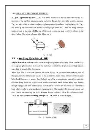
completely.
4. 4
2.2 CONVERSION OF SOLAR ENERGY TO ELECTRIC ENERGY
[Refer to no. 02 under section titled ‘References’]
Fig: - 1 – Conversion of Solar Energy to Electric Energy
As we can see that the basic principle of solar conversion requires a solar panel or solar cell
for the conversion.
Light striking a silicon semiconductor causes electrons to flow, creating electricity. Solar
power generating systems take advantage of this property to convert sunlight directly into
electrical energy.
Solar panels (also called “solar modules”) produce direct current (DC), which goes through a
power inverter to become alternating current (AC) — electricity that we can use in the home
or office, like that supplied by a utility power company.
There are two types of solar power generating systems: grid-connected systems, which are
connected to the commercial power infrastructure; and stand-alone systems, which feed
electricity to a facility for immediate use, or to a battery for storage.
Grid-connected systems are used for homes, public facilities such as schools and hospitals,
and commercial facilities such as offices and shopping centers. Electricity generated during
5. 5
the daytime can be used right away, and in some cases surplus electricity can be sold to the
utility power company. If the system doesn’t generate enough electricity, or generates none at
all (for example, on a cloudy or rainy day, or at night) electricity is purchased from the utility
power company. Power production levels and surplus selling can be checked in real time on a
monitor, an effective way to gauge daily energy consumption.
Stand-alone systems are used in a variety of applications, including emergency power supply
and remote power where traditional infrastructure is unavailable.
Fig: - 2 – Working of solar cell
When sunlight hits the semiconductor, an electron springs up and is attracted to the n-type
semiconductor. This causes more negative electrons in the n-type semiconductor and more
positive electrons in the p-type, thus generating a flow of electricity in a process known as the
“photovoltaic effect.”
Fig: - 3 Solar Cell
6. 6
2.2 Some of Applications of solar energy
[Refer to No.03 under section titled ‘References’]
1. Power plants: In conventional power plants non-renewable energy sources are used to boil
water and form stream so that turbines can rotate and water to produce electricity. But with
application of solar energy heat of sun can boil that water to create steam and rotate turbines.
To convert sunlight into electricity solar panels, photoelectric technologies and
thermoelectric technologies etc are used.
2. Homes: Use of solar energy is increasing in homes as well. Residential appliances can easily
use electricity generated through solar power. Besides this solar energy is running solar
heater to supply hot water in homes. Through photovoltaic cell installed on the roof of the
house energy is captured and stored on batteries to use throughout the day at homes for
different purposes. In this ways expenditure on energy is cutting down by home users.
3. Commercial use: on roofs of different buildings we can find glass PV modules or any other
kind of solar panel. These panels are used there to supply electricity to different offices or
other parts of building in a reliable manner. These panels collect solar energy from sun,
convert it into electricity and allow offices to use their own electrical power for different
purposes.
4. Ventilation system: at many places solar energy is used for ventilation purposes. It helps in
running bath fans, floor fans, and ceiling fans in buildings. Fans run almost every time in a
building to control moisture, and smell and in homes to take heat out of the kitchen. It can
add heavy amount on the utility bills, to cut down these bills solar energy is used for
ventilation purposes.
5. Power pump: solar power not just help in improving ventilation system at your homes but
with that it can also help in circulating water in any building. You can connect power pump
with solar power supply unit but you must run it on DC current so that water circulate
throughout your home.
6. Swimming pools: swimming pools are great joy for kids and adults in all seasons. But during
winters it is tough to keep water hot in these pools with minimum power usage. Solar energy
can help many in this matter as well. You can add a solar blanket in the pool that will keep
the water hot with energy generated from sunlight. Besides this you can install a solar hot
water heating system with solar hot water heating panels.
7. 7
7. Solar Lighting: these lights are also known as day lighting, and work with help of solar
power. These lights store natural energy of sun in day time and then convert this energy into
electricity to light up in night time. Use of this system is reducing load form local power
plants.
8. Solar Cars: it is an electrical vehicle which is recharged form solar energy or sunlight. Solar
panels are used on this car that absorb light and then convert it into electrical energy. This
electrical energy is stored in batteries used with the car, so that in night time as well we can
drive these vehicles.
9. Remote applications: Remote buildings are taking benefit of solar energy at vast scale.
Remote schools, community halls, and clinics can take solar panel and batteries with them
anywhere to produce and use electric power.
2.4 Solar Integrated Smart Street Lighting System
[Refer to no. 04 under section titled ‘References’]
Fig.4 – Solar integrated smart street lights
8. 8
Solar street lights are raised light sources which are powered by photovoltaic panels generally
mounted on the lighting structure or integrated in the pole itself. The photovoltaic panels
charge a rechargeable battery, which powers a fluorescent or LED lamp during the night.
Components
Solar powered street lights
Solar street lights consist of 5 main parts:
A. Solar Panel - The solar panel is one of the most important parts of solar street lights, as
the solar panel will convert solar energy into electricity. Solar panel are varies from
wattage systems.
B. Lighting Fixture - LED is usually used as lighting source of modern solar street light, as
the LED will provide much higher Lumens with lower energy consumption. The energy
consumption of LED fixture is at least 50% lower than HPS fixture which is widely used
as lighting source in Traditional street lights. LEDs lack of warm up time also allows for
use of motion detectors for additional efficiency gains.
C. Rechargeable Battery - Battery will store the electricity from solar panel during the day
and provide energy to the fixture during night. The life cycle of the battery is very
important to the lifetime of the light and the capacity of the battery will affect the backup
days of the lights. There are usually 2 types of batteries: Gel Cell Deep Cycle Battery and
Lead Acid Battery and many more.
D. Controller - Controller is also very important for solar street light. A controller will
usually decide to switch on /off charging and lighting. Some modern controllers are
programmable so that user can decide the appropriate change of charging, lighting and
dimming.
E. Pole - Strong Poles are necessary to all street lights, especially to solar street lights as
there are often components mounted on the top of the pole: fixtures, panels and
sometimes batteries. However, in some newer designs, the PV panels and all electronics
are integrated in the pole itself. Wind resistance is also a factor.
Advantages
A. Solar street lights are independent of the utility grid. Hence, the operation costs are
minimized.
B. Solar street lights require much less maintenance compared to conventional street lights.
C. Since external wires are eliminated, risk of accidents is minimized.
D. This is a non-polluting source of electricity.
E. Separate parts of solar system can be easily carried to the remote areas.
9. 9
CHAPTER- 3
COMPONENTS ESSENTIAL FOR THE PROJECT
3.1 NPN Transistor
[Refer to No.05 under section titled ‘References’]
A bipolar junction transistor (bipolar transistor or BJT) is a type of transistor that uses
both electron and hole charge carriers. In contrast, unipolar transistors, such as field-effect
transistors, only use one kind of charge carrier. For their operation, BJTs use two junctions
between two semiconductor types, n-type and p-type. BJTs are manufactured in two types,
NPN and PNP, and are available as individual components, or fabricated in integrated circuits,
often in large numbers. The basic function of a BJT is to amplify current. This allows BJTs to
be used as amplifiers or switches, giving them wide applicability in electronic equipment,
including, computers, televisions, mobile phones, audio amplifiers, industrial control, and
radio transmitters
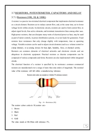
Bipolar transistors have five distinct regions of operation, defined by BJT junction biases.
Forward-active (or simply, active): The base–emitter junction is forward biased and the
base–collector junction is reverse biased. Most bipolar transistors are designed to afford
the greatest common-emitter current gain, βF, in forward-active mode. If this is the case,
the collector–emitter current is approximately proportional to the base current, but many
times larger, for small base current variations.
Reverse-active (or inverse-active or inverted): By reversing the biasing conditions of
the forward-active region, a bipolar transistor goes into reverse-active mode. In this mode,
the emitter and collector regions switch roles. Because most BJTs are designed to
maximize current gain in forward-active mode, the βF in inverted mode is several times
smaller (2–3 times for the ordinary germanium transistor). This transistor mode is seldom
used, usually being considered only for failsafe conditions and some types of bipolar
logic. The reverse bias breakdown voltage to the base may be an order of magnitude
lower in this region.
Saturation: With both junctions forward-biased, a BJT is in saturation mode and
facilitates high current conduction from the emitter to the collector (or the other direction
10. 10
in the case of NPN, with negatively charged carriers flowing from emitter to collector).
This mode corresponds to a logical "on", or a closed switch.
Cutoff: In cutoff, biasing conditions opposite of saturation (both junctions reverse biased)
are present. There is very little current, which corresponds to a logical "off", or an open
switch.
Table: - 4.1- Mode of work of N-P-N Transistor
The modes of operation can be described in terms of the applied voltages (this description
applies to NPN transistors; polarities are reversed for PNP transistors)
Forward-active: base higher than emitter, collector higher than base (in this mode the
collector current is proportional to base current by ).
Saturation: base higher than emitter, but collector is not higher than base.
Cut-Off: base lower than emitter, but collector is higher than base. It means the transistor is
not letting conventional current go through from collector to emitter.
Reverse-active: base lower than emitter, collector lower than base: reverse conventional
current goes through transistor.
In terms of junction biasing: ('reverse biased base–collector junction' means Vbc< 0 for NPN,
opposite for PNP)
Although these regions are well defined for sufficiently large applied voltage, they overlap
somewhat for small (less than a few hundred mili volts) biases. For example, in the typical
grounded-emitter configuration of an NPN BJT used as a pull down switch in digital logic,
the "off" state never involves a reverse-biased junction because the base voltage never goes
below ground; nevertheless the forward bias is close enough to zero that essentially no
current flows, so this end of the forward active region can be regarded as the cutoff region.
Applied voltages B-E junction
bias (NPN)
B-C junction
bias (NPN)
Mode (NPN)
E < B < C Forward Reverse Forward-active
E < B > C Forward Forward Saturation
E > B < C Reverse Reverse Cut-off
E > B > C Reverse Forward Reverse-active
11. 11
3.1.1 Active-mode NPN transistors in circuits
Fig: - 5 – Structure and Use of NPN transistor
The diagram shows a schematic representation of an NPN transistor connected to two voltage
sources. To make the transistor conduct appreciable current (on the order of 1 mA) from C to
E, VBE must be above a minimum value sometimes referred to as the cut-in voltage. The cut-
in voltage is usually about 650 mV for silicon BJTs at room temperature but can be different
depending on the type of transistor and its biasing. This applied voltage causes the lower P-N
junction to 'turn on', allowing a flow of electrons from the emitter into the base. In active
mode, the electric field existing between base and collector (caused by VCE) will cause the
majority of these electrons to cross the upper P-N junction into the collector to form the
collector current IC. The remainder of the electrons recombines with holes, the majority
carriers in the base, making a current through the base connection to form the base current, IB.
As shown in the diagram, the emitter current, IE, is the total transistor current, which is the
sum of the other terminal currents, (i.e., IE = IB + IC).
In the diagram, the arrows representing current point in the direction of conventional
current – the flow of electrons is in the opposite direction of the arrows because electrons
carry negative electric charge. In active mode, the ratio of the collector current to the base
current is called the DC current gain. This gain is usually 100 or more, but robust circuit
designs do not depend on the exact value (for example see op-amp). The value of this gain for
DC signals is referred to as Hfe, and the value of this gain for small signals is referred to
as Hfe That is, when a small change in the currents occurs, and sufficient time has passed for
the new condition to reach a steady state Hfe is the ratio of the change in collector current to
the change in base current. The symbol β is used for both Hfe and Hfe.[9]
12. 12
The emitter current is related to VBE exponentially. At room temperature, an increase
in VBE by approximately 60 mV increases the emitter current by a factor of 10. Because the
base current is approximately proportional to the collector and emitter currents, they vary in
the same way.
Fig: - 6 – Avalanche Breakdown Region
A Bipolar NPN Transistor Configuration
Fig: - 7 – Configuration of NPN Transistor
(Note: Arrow defines the emitter and conventional current flow, “out” for a Bipolar NPN
Transistor.)
The construction and terminal voltages for a Bipolar NPN Transistor are shown above. The
voltage between the Base and Emitter ( VBE ), is positive at the Base and negative at the
Emitter because for an NPN transistor, the Base terminal is always positive with respect to
13. 13
the Emitter. Also the Collector supply voltage is positive with respect to the Emitter (VCE ).
So for a bipolar NPN transistor to conduct the Collector is always more positive with respect
to both the Base and the Emitter.
Fig: - 8 - NPN Transistor Connection
Then the voltage sources are connected to an NPN transistor as shown. The Collector is
connected to the supply voltage VCC via the load resistor, RL which also acts to limit the
maximum current flowing through the device. The Base supply voltage VB is connected to
the Base resistor RB, which again is used to limit the maximum Base current.
So in a NPN Transistor it is the movement of negative current carriers (electrons) through the
Base region that constitutes transistor action, since these mobile electrons provide the link
between the Collector and Emitter circuits. This link between the input and output circuits is
the main feature of transistor action because the transistors amplifying properties come from
the consequent control which the Base exerts upon the Collector to Emitter current.
Then we can see that the transistor is a current operated device (Beta model) and that a large
current (IC ) flows freely through the device between the collector and the emitter terminals
when the transistor is switched “fully-ON”. However, this only happens when a small biasing
current ( IB ) is flowing into the base terminal of the transistor at the same time thus allowing
the Base to act as a sort of current control input.
The transistor current in a bipolar NPN transistor is the ratio of these two currents ( IC / IB ),
called the DC Current Gain of the device and is given the symbol of Hfe or nowadays Beta
(β). The value of β can be large up to 200 for standard transistors, and it is this large ratio
between IC and IB that makes the bipolar NPN transistor a useful amplifying device when
used in its active region as IB provides the input and IC provides the output. Note
that Beta has no units as it is a ratio.
14. 14
Also, the current gain of the transistor from the Collector terminal to the Emitter terminal, IC
/ IE , is called Alpha ( α ), and is a function of the transistor itself (electrons diffusing across
the junction). As the emitter current IE is the sum of a very small base current plus a very
large collector current, the value of alpha α, is very close to unity, and for a typical low-
power signal transistor this value ranges from about 0.950 to 0.999.
DC Current Gain =
Output Current
Input Current
=
IC
IB
IE = IB + IC … … … (KCL) And
IC
IE
= α
Thus, IB = IE − IC
IB = IE − αIE
IB = IE (1 − α)
i.e. β =
IC
IB
=
IC
IE(1−α)
=
α
1−α
By combining the two parameters α and β we can produce two mathematical expressions that
give the relationship between the different currents flowing in the transistor.
α =
β
β + 1
or α = β(1 − α)
β =
α
1 − α
or β = α(1 + β)
If,
α = 0.99 and β =
0.99
0.01
= 99
The values of Beta vary from about 20 for high current power transistors to well over 1000
for high frequency low power type bipolar transistors. The value of Beta for most standard
NPN transistors can be found in the manufactures data sheets but generally range between 50
and 200.
The equation above for Beta can also be re-arranged to make IC as the subject, and with a
zero base current ( IB = 0 ) the resultant collector current IC will also be zero, ( β x 0 ). Also
when the base current is high the corresponding collector current will also be high resulting
in the base current controlling the collector current. One of the most important properties of
the Bipolar Junction Transistor is that a small base current can control a much larger collector
current.
15. 15
In this project BC547 transistor is used.
Fig: - 9 – Symbol of BC547
3.1.2 BC547 Transistor Specification
[Refer to No.06 under section titled ‘References’]
Datasheet and Parameters -
Type Designator: BC547
Material of transistor: Si
Polarity: NPN
Maximum collector power dissipation ( Pc ), W : 0.5
Maximum collector-base voltage ( Vcb ), V : 50
Maximum collector-emitter voltage ( Vce ), V : 50
Maximum emitter-base voltage ( Veb ), V : 6
Maximum collector current ( IC max), A : 0.1
Maximum temperature ( Tj ),°C : 150
Transition frequency ( ft ), MHz : 300
Collector capacitance ( CC ), pF : 6
Forward current transfer ratio ( Hfe ), min : 110
16. 16
SPECFICATION IN DETAILS
1. Power Ratings-
The rated power dissipation for transistors is the total power developed across both junctions
of the transistor that will raise the internal temperature to the maximum permitted (i.e. not
something that should be maintained in normal use), and will be specified for a given ambient
temperature for low-power transistors such as these, in this case 25 degrees Celsius. In
practice factors such as the proximity of the transistor to the printed circuit board will
influence how well heat can be removed from the transistor and proximity to other heat-
generating components will increase the ambient temperature - and probably reduce the
permissible dissipation below the 500-625 mW ideal-conditions specification.
2. Voltage ratings-
The BC547 and BC548, and their PNP counterparts (BC558 and BC559) can be used in
circuits where voltages reach no more than 30 Volts, limited mainly by their VCEO rating. The
VCBO rating refers to the maximum voltage between collector and base with the emitter open-
circuit (not typical operation), and their predecessors, the BC108 and BC109, while having
VCBO or VCES ratings of 30 V have only a 20 VCEO) rating, meaning a BC548 (or BC549) can
replace a BC108 but a BC108 might not be a safe replacement for a BC148.
3. Variants-
The BC546 and BC547 have higher voltage ratings; the BC549 has lower noise, and the
BC550 has both higher voltage and lower noise, and the last digit of the type number follows
a pattern common to several other transistors tabulated for the BC108 family of transistors.
Some manufacturers specify their parts with higher ratings, for example the Fairchild 1997
datasheet (547ABC, Rev B) for the BC547, sourced from Process 10 gave 500mA as the
maximum collector current, and while their datasheets dated 2002 have dropped the current
rating to the standard 100mA.
PNP Versions of BC547-The PNP counterparts of the BC546 to BC550 are the BC556 to
BC560 respectively, i.e. the type numbers are higher by ten.
17. 17
[Refer to No.07under section titled ‘References’](applicable up to 3.11)
3.2 DIODE
In electronics, a diode is a two-terminal electronic component that conducts primarily in one
direction (asymmetric conductance); it has low (ideally zero) resistance to the flow
of current in one direction, and high (ideally infinite) resistance in the other. A semiconductor
diode, the most common type today, is a crystalline piece of semiconductor material with
a p–n junction connected to two electrical terminals.[5] A vacuum tube diode has
two electrodes, a plate (anode) and a heated cathode. Semiconductor diodes were the first
semiconductor electronic devices. The discovery of crystals' rectifying abilities was made by
German physicist Ferdinand Braun in 1874. The first semiconductor diodes, called cat's
whisker diodes, developed around 1906, were made of mineral crystals such as galena. Today,
most diodes are made of silicon, but other semiconductors such
as selenium or germanium are sometimes used.
Types of semiconductor Diode
There are several types of p–n junction diodes, which emphasize either a different physical
aspect of a diode often by geometric scaling, doping level, choosing the right electrodes, are
just an application of a diode in a special circuit, or are really different devices like the Gunn
and laser diode and the MOSFET:
Normal (p–n) diodes, which operate as described above, are usually made of doped silicon or,
more rarely, germanium. Before the development of silicon power rectifier diodes, cuprous
oxide and later selenium was used. Their low efficiency required a much higher forward
voltage to be applied (typically 1.4 to 1.7 V per "cell", with multiple cells stacked so as to
increase the peak inverse voltage rating for application in high voltage rectifiers), and
required a large heat sink (often an extension of the diode's metal substrate), much larger than
the later silicon diode of the same current ratings would require. The vast majority of all
diodes are the p–n diodes found in CMOS integrated circuits, which include two diodes per
pin and many other internal diodes.
Fig: - 10 – Diodes (IN4007)
18. 18
3.3 LED (LIGHT EMITTING DIODE)
A light-emitting diode (LED) is a two-lead semiconductor light source. It is a p–n
junction diode, which emits light when activated. When a suitable voltage is applied to the
leads, electrons are able to recombine with electron holes within the device, releasing energy
in the form of photons. This effect is called electroluminescence, and the color of the light
(corresponding to the energy of the photon) is determined by the energy band gap of the
semiconductor.
Fig: - 11 – LED
3.4 ELECTRICAL CONNECTOR
An electrical connector is an electro-mechanical device for joining electrical circuits as an
interface using a mechanical assembly. Connectors consist of plugs (male-ended) and jacks
(female-ended). The connection may be temporary, as for portable equipment, require a tool
for assembly and removal, or serve as a permanent electrical joint between two wires or
devices. An adapter can be used to effectively bring together dissimilar connectors.
There are hundreds of types of electrical connectors. Connectors may join two lengths of
flexible copper wire or cable, or connect a wire or cable to an electrical terminal. Side bind
connectors are used in the project.
Fig: - 12 – Electrical Connector
19. 19
3.5 VOLTAGE REGULATOR (IC 7812)
A voltage regulator is one of the most widely used electronic circuitry in any device. A
regulated voltage (without fluctuations & noise levels) is very important for the smooth
functioning of many digital electronic devices. A common case is with micro controllers,
where a smooth regulated input voltage must be supplied for the micro controller to function
smoothly.
Voltage regulators are of different types. In this article, our interest is only with IC based
voltage regulator. An example of IC based voltage regulator available in market is the
popular 7805 IC which regulates the output voltage at 5 volts. Now let’s come to the basic
definition of an IC voltage regulator. It is an integrated circuit whose basic purpose is to
regulate the unregulated input voltage (definitely over a predefined range) and provide with a
constant, regulated output voltage.
An IC based voltage regulator can be classified in different ways. A common type of
classification is 3 terminal voltage regulator and 5 or multi terminal voltage regulator.
Another popular way of classifying IC voltage regulators is by identifying them as linear
voltage regulator & switching voltage regulator. There is a third set of classification as 1)
Fixed voltage regulators (positive & negative) 2) Adjustable voltage regulators (positive &
negative) and finally 3) Switching regulators. In the third classification, fixed & adjustable
regulators are basically versions of linear voltage regulators.
Fixed Voltage Regulators
These regulators provide a constant output voltage. A popular example is the 7805 IC which
provides a constant 5 volts output. A fixed voltage regulator can be a positive voltage
regulator or a negative voltage regulator. A positive voltage regulator provides with constant
positive output voltage. All those IC’s in the 78XX series are fixed positive voltage
regulators. In the IC nomenclature – 78XX; the part XX denotes the regulated output voltage
the IC is designed for. Examples: - 7805, 7806, 7809 etc.
A negative fixed voltage regulator is same as the positive fixed voltage regulator in design,
construction & operation. The only difference is in the polarity of output voltages. These IC’s
are designed to provide a negative output voltage. Example: - 7905, 7906 and all those IC’s
in the 79XX series.
20. 20
Fig: - 13 – Regulators (7812)
Adjustable Voltage Regulator
An adjustable voltage regulator is a kind of regulator whose regulated output voltage can be
varied over a range. There are two variations of the same; known as positive adjustable
voltage regulator and negative adjustable regulator. LM317 is a classic example of positive
adjustable voltage regulator, whose output voltage can be varied over a range of 1.2 volts to
57 volts. LM337 is an example of negative adjustable voltage regulator. LM337 is actually a
complement of LM317 which are similar in operation & design; with the only difference
being polarity of regulated output voltage.
Fig: - 14 – Adjustable Voltage Regulator (LM317)
21. 21
3.6 TRANSFORMER (230V/12V, 1Amp, 12VA)
Electrical power transformer is a static device which transforms electrical energy from one
circuit to another without any direct electric connection and with the help of mutual induction
between two windings. It transforms power from one circuit to another without changing its
frequency but may be in different voltage level.
A transformer is made of a soft iron coil with two other coils wound around it, but not
connected with one another. The iron coils can either be arranged on top of another or be
wound on separate limps of the iron core. The coil to which the alternating voltage is
supplied is known as primary winding or primary coil while. The alternating current in the
primary winding produces a changing magnetic field around it whenever an alternating
potential is supplied. An alternating current is in turn produced by the changing field in the
secondary coil and the amount of current produced depends on the number of windings in the
secondary coil. There are two types of transformers, namely: Step down and Step up
transformers. Generally, the difference between them is the amount of voltage produced,
depending on the number of secondary coils. A transformer is made of a soft iron coil with
two other coils wound around it, but not connected with one another. The iron coils can either
be arranged on top of another or be wound on separate limps of the iron core. The coil to
which the alternating voltage is supplied is known as primary winding or primary coil while.
The alternating current in the primary winding produces a changing magnetic field around it
whenever an alternating potential is supplied. An alternating current is in turn produced by
the changing field in the secondary coil and the amount of current produced depends on the
number of windings in the secondary coil. There are two types of transformers, namely: Step
down and Step up transformers. Generally, the difference between them is the amount of
voltage produced, depending on the number of secondary coils.
Step-Down Transformer
The relationship between the voltage and the number of turns in each coil
is given by –
Voltage in Secondary Coil
Voltage in Primary Coil
=
Turns on Secondary Coil
Turns on Primary Coil
Or
VS
VP
=
NS
NP
22. 22
When VS is less than VP ,that means the transformer is a step down transformer.
A step down transformer has less turns on the secondary coil than the primary coil. The
induced voltage across the secondary coil is less the applied voltage across the primary coil
or in other words the voltage is “stepped-down”.
Fig: - 15 - Transformer
In fig: 17 we can see a step down transformer which is used in our project. This transformer
has the following ratings- 230V/12V, 1 Amp, 12 VA. In this project the transformer is used
for the purpose of emergency backup system. A rectifier circuit is used the transformer for
getting DC output.
23. 23
3.7 RESISTORS, POTENTIOMETER, CAPACITORS AND RELAY
3.7.1 Resistors (10K,1K & 100K)
A resistor is a passive two-terminal electrical component that implements electrical resistance
as a circuit element. Resistors act to reduce current flow, and, at the same time, act to lower
voltage levels within circuits. In electronic circuits, resistors are used to limit current flow, to
adjust signal levels, bias active elements, and terminate transmission lines among other uses.
High-power resistors, that can dissipate many watts of electrical power as heat, may be used
as part of motor controls, in power distribution systems, or as test loads for generators. Fixed
resistors have resistances that only change slightly with temperature, time or operating
voltage. Variable resistors can be used to adjust circuit elements (such as a volume control or
a lamp dimmer), or as sensing devices for heat, light, humidity, force, or chemical activity.
Resistors are common elements of electrical networks and electronic circuits and are
ubiquitous in electronic equipment. Practical resistors as discrete components can be
composed of various compounds and forms. Resistors are also implemented within integrated
circuits.
The electrical function of a resistor is specified by its resistance: common commercial
resistors are manufactured over a range of more than nine orders of magnitude. The nominal
value of the resistance will fall within a manufacturing tolerance.
Fig: - 16 – Resistance (1K)
The resistor colour codes in 1K resistor are:-
1. Brown
2. Black
3. Red
4. Gold
The value stands at 10k Ohms with tolerance 5%.
24. 24
3.7.2 Potentiometer (10K)
A potentiometer, informally a pot, is a three-terminal resistor with a sliding or rotating con
tact that forms an adjustable voltage divider. If only two terminals are used, one end and the
wiper, it acts as a variable resistor or rheostat.
The measuring instrument called a potentiometer is essentially a voltage divider used for
measuring electric potential (voltage); the component is an implementation of the same
principle, hence its name.
Potentiometers are commonly used to control electrical devices such as volume controls on
audio equipment. Potentiometers operated by a mechanism can be used as
position transducers, for example, in a joystick. Potentiometers are rarely used to directly
control significant power (more than a watt), since the power dissipated in the potentiometer
would be comparable to the power in the control.
Fig: - 17 – Potentiometer (10K)
25. 25
3.7.3 Capacitors (470uF, 0.1uF)
A capacitor (originally known as a condenser) is a passive two-terminal electrical
component used to store electrical energy temporarily in an electric field. The forms of
practical capacitors vary widely, but all contain at least two electrical conductors(plates)
separated by a dielectric (i.e. an insulator that can store energy by becoming polarized). The
conductors can be thin films, foils or sintered beads of metal or conductive electrolyte, etc.
The non-conducting dielectric acts to increase the capacitor's charge capacity. A dielectric
can be glass, ceramic, plastic film, air, vacuums, paper, mica, oxide layer etc. Capacitors are
widely used as parts of electrical circuits in many common electrical devices. Unlike
a resistor, an ideal capacitor does not dissipate energy. Instead, a capacitor stores energy in
the form of an electrostatic field between its plates.
When there is a potential difference across the conductors (e.g., when a capacitor is attached
across a battery), an electric field develops across the dielectric, causing
positive charge +Q to collect on one plate and negative charge −Q to collect on the other
plate. If a battery has been attached to a capacitor for a sufficient amount of time, no current
can flow through the capacitor. However, if a time-varying voltage is applied across the leads
of the capacitor, a displacement current can flow.
The larger the surface area of the "plates" (conductors) and the narrower the gap between
them, the greater the capacitance is. In practice, the dielectric between the plates passes a
small amount of leakage current and also has an electric field strength limit, known as the
breakdown voltage. The conductors and leads introduce an undesired inductance and
resistance.
Capacitors are widely used in electronic circuits for blocking direct current while
allowing alternating current to pass. In filter networks, they smooth the output of power
supplies. In resonant circuits they tune radios to particular frequencies. In electric power
transmission systems, they stabilize voltage and power flow.
Fig: - 18 - Capacitors (470uf)
26. 26
3.7.3 Relay
What is a relay?
We know that most of the high end industrial application devices have relays for their
effective working. Relays are simple switches which are operated both electrically and
mechanically. Relays consist of a n electromagnet and also a set of contacts. The switching
mechanism is carried out with the help of the electromagnet. There are also other operating
principles for its working. But they differ according to their applications. Most of the devices
have the application of relays.
Why is a relay used?
The main operation of a relay comes in places where only a low-power signal can be used to
control a circuit. It is also used in places where only one signal can be used to control a lot of
circuits. The application of relays started during the invention of telephones. They played an
important role in switching calls in telephone exchanges. They were also used in long
distance telegraphy. They were used to switch the signal coming from one source to another
destination. After the invention of computers they were also used to perform Boolean and
other logical operations. The high end applications of relays require high power to be driven
by electric motors and so on. Such relays are called contactors.
Different Types of Relay:-
Relays are remote control electrical switches that are controlled by another switch, such as a
horn switch or a computer as in a power train module. Relays allow a small current flow
circuit to control a higher current circuit. Several designs of relays are in use today, 3-pin, 4-
pin, 5-pin, and 6- pin, single switch or dual switches. Relays which come in various sizes,
ratings, and applications, are used as remote control switches. Fig. 5 shows different types of
relays. In this paper, the 4-pin relay will be used.
27. 27
Fig: - 19 – Different types of Relay
Relay Construction:-
It is an electro-magnetic relay with a wire coil, surrounded by an iron core. A path of very
low reluctance for the magnetic flux is provided for the movable armature and also the switch
point contacts. The movable armature is connected to the yoke which is mechanically
connected to the switch point contacts. These parts are safely held with the help of a spring.
The spring is used so as to produce an air gap in the circuit when the relay becomes de-
energized.
Application of Relay
Selection of an appropriate relay for a particular application requires evaluation of many
different factors:
Number and type of contacts – normally open, normally closed, (double-throw)
Contact sequence – "Make before Break" or "Break before Make". For example, the old
style telephone exchanges required Make-before-break so that the connection didn't get
dropped while dialing the number.
Contact current rating – small relays switch a few amperes, large contactors are rated for
up to 3000 amperes, alternating or direct current.
Contact voltage rating – typical control relays rated 300 VAC or 600 VAC, automotive
types to 50 VDC, special high-voltage relays to about 15,000 V.
28. 28
Operating lifetime, useful life - the number of times the relay can be expected to operate
reliably. There is both a mechanical life and a contact life. The contact life is affected by
the type of load switched. Breaking load current causes undesired arcing between the
contacts, eventually leading to contacts that weld shut or contacts that fail due erosion by
the arc.
Coil voltage – machine-tool relays usually 24 VDC, 120 or 250 VAC, relays for
switchgear may have 125 V or 250 VDC coils.
Coil current - Minimum current required for reliable operation and minimum holding
current, as well as, effects of power dissipation on coil temperature, at various duty cycles.
"Sensitive" relays operate on a few mili amperes.
Package/enclosure – open, touch-safe, double-voltage for isolation between
circuits, explosion proof, outdoor, oil and splash resistant, washable for printed
circuit board assembly.
Fig: - 20 - Relay (12V)
29. 29
3.8 – LDR (LIGHT DEPENDENT RESISTOR)
A Light Dependent Resistor (LDR) or a photo resistor is a device whose resistivity is a
function of the incident electromagnetic radiation. Hence, they are light sensitive devices.
They are also called as photo conductors, photo conductive cells or simply photocells. They
are made up of semiconductor materials having high resistance. There are many different
symbols used to indicate a LDR, one of the most commonly used symbol is shown in the
figure below. The arrow indicates light falling on it.
Fig: - 21 - LDR
3.8.1 - Working Principle of LDR
A light dependent resistor works on the principle of photo conductivity. Photo conductivity
is an optical phenomenon in which the materials conductivity (Hence resistivity) reduces
when light is absorbed by the material.
When light falls i.e. when the photons fall on the device, the electrons in the valence band of
the semiconductor material are excited to the conduction band. These photons in the incident
light should have energy greater than the band gap of the semiconductor material to make the
electrons jump from the valence band to the conduction band. Hence when light having
enough energy is incident on the device more & more electrons are excited to the conduction
band which results in large number of charge carriers. The result of this process is more and
more current starts flowing and hence it is said that the resistance of the device has decreased.
This is the most common working principle of LDR and it is shown in figure.
Fig: - 22 – Working of LDR
30. 30
3.8.2 - Characteristics of LDR
LDR’s are light dependent devices whose resistance decreases when light falls on them and
increases in the dark. When a light dependent resistor is kept in dark, its resistance is very
high. This resistance is called as dark resistance. It can be as high as 1012 Ω. And if the
device is allowed to absorb light its resistance will decrease drastically. If a constant voltage
is applied to it and intensity of light is increased the current starts increasing. Figure below
shows resistance vs. illumination curve for a particular LDR.
Fig: - 23(a) – Characteristics of LDR
Photocells or LDR’s are non-linear devices. There sensitivity varies with the wavelength of
light incident on them. Some photocells might not at all response to a certain range of
wavelengths. Based on the material used different cells have different spectral response
curves.
When light is incident on a photocell it usually takes about 8 to 12ms for the change in
resistance to take place, while it takes seconds for the resistance to rise back again to its
initial value after removal of light. This phenomenon is called as resistance recovery rate.
This property is used in audio compressors. Also, LDR’s are less sensitive than photo diodes
and photo transistor. (A photo diode and a photocell (LDR) are not the same, a photo-diode is
a p-n junction semiconductor device that converts light to electricity, whereas a photocell is a
passive device, there is no p-n junction in this nor it “converts” light to electricity).
31. 31
Fig: - 23(b) – Characteristics of LDR
The most common type of LDR has a resistance that falls with an increase in the light
intensity falling upon the device (as shown in the graph). The resistance of an LDR may
typically have the following resistances:
• Daylight = 5000 ohms
• Dark = 20000000 ohms
3.8.3 - Types of Light Dependent Resistors:
Based on the materials used they are classified as:
i) Intrinsic photo resistors (Undoped semiconductor): These are pure semiconductor materials
such as silicon or germanium. Electrons get excited from valance band to conduction band
when photons of enough energy falls on it and number charge carriers increases.
ii) Extrinsic photo resistors: These are semiconductor materials doped with impurities which
are called as dopants. Theses dopants create new energy bands above the valence band which
are filled with electrons. Hence this reduces the band gap and less energy is required in
exciting them. Extrinsic photo resistors are generally used for long wavelengths.
32. 32
3.8.4 - Applications of LDR
LDR’s have low cost and simple structure.
They are often used as light sensors.
They are used when there is a need to detect absences or presences of light like in a
camera light meter.
Used in street lamps, alarm clock and burglar alarm circuits.
Used in light intensity meters, for counting the packages moving on a conveyor belt, etc.
Fig: - 24 – Types of LDR
3.9 Construction of a Photocell
The structure of a light dependent resistor consists of a light sensitive material which is
deposited on an insulating substrate such as ceramic. The material is deposited in zigzag
pattern in order to obtain the desired resistance & power rating.
What is a Photoconductive Cell?
Semiconductor light detectors can be divided into two major categories: junction and bulk
effect devices. Junction devices, when operated in the photoconductive mode, utilize the
reverse characteristic of a PN junction. Under reverse bias, the PN junction acts as a light
controlled current source. Output is proportional to incident illumination and is relatively
independent of implied voltage as shown in Figure 1. Silicon photodiodes are examples of
this type detector.
33. 33
Fig: - 26 – Double Pole Switch Fig: - 27 – Triple Pole Switch
Fig: - 25 – Construction of Photocell
Why Use Photocells?
Photocells can provide a very economic and technically
superior solution for many applications where the
presence or absence of light is sensed (digital operation)
or where the intensity of light needs to be measured
(analog operation). Their general characteristics and
features can be summarized as follows: Lowest cost
available and near-IR photo detector • Available in low
cost plastic encapsulated packages as well as hermetic
packages (TO-46, TO-5, TO-8). Responsive to both very low light levels (moonlight) and to
very high light levels (direct sunlight). Wide dynamic range: resistance changes of several
orders of magnitude between "light" and "no light" • Low noise distortion. Maximum
operating voltages of 50 to 400 volts are suitable for operation on 120/240 VAC. Available in
center tap dual cell configurations as well as specially selected resistance ranges for special
applications. Easy to use in DC or AC circuits - they are a light variable resistor and hence
symmetrical with respect to AC waveforms. Usable with almost any visible or near infrared
light
3.10 DOUBLE POLE & TRIPLE POLE SWITCH
In electrical engineering, a switch is an electrical component that can break an electrical
circuit, interrupting the current or diverting it from one conductor to another. The mechanism
of a switch may be operated directly by a human operator to control a circuit (for example, a
light switch or a keyboard button), may be operated by a moving object such as a door-
operated switch, or may be operated by some sensing element for pressure, temperature or
flow.
34. 34
Fig: - 28 – Solar Panel
There are various kinds of switches with terminologies relating to Pole and Throw. Double
pole - double throw and triple pole double throw switch is used for this project.
3.11 – SOLAR PANEL AND BATTERY
3.11.1 – Solar Panel
Solar panel refers to a panel designed
to absorb the sun's rays as a source of
energy for generating electricity or
heating.
A photovoltaic (in short PV) module is
a packaged, connected assembly of
typically 6×10 solar cells. Solar
Photovoltaic panels constitute the solar
array of a photovoltaic system that
generates and supplies solar electricity
in commercial and residential
applications. Each module is rated by
its DC output power under standard
test conditions, and typically ranges
from 100 to 365 watts. The efficiency
of a module determines the area of a module given the same rated output – an 8% efficient
230 watt module will have twice the area of a 16% efficient 230 watt module. There are a
few solar panels available that are exceeding 19% efficiency. A single solar module can
produce only a limited amount of power; most installations contain multiple modules. A
35. 35
photovoltaic system typically includes a panel or an array of solar modules, a solar inverter,
and sometimes a battery and/or solar tracker and interconnection wiring.
Fig: - 29 – Specifications of Solar Panel
36. 36
3.11.2 – Battery
An electric battery is a device consisting of one or more electrochemical cells with external
connections provided to power electrical devices. A discharging battery has a positive
terminal, or cathode, and a negative terminal, or anode. The terminal marked negative is the
source of electrons that when connected to an external circuit will flow and deliver energy to
an external device. When a battery is connected to an external circuit, electrolytes are able to
move as ions within, allowing the chemical reactions to be completed at the separate
terminals and so deliver energy to the external circuit. It is the movement of those ions within
the battery which allows current to flow out of the battery to perform work.
Fig: - 30 - 12V Battery
37. 37
Fig: - 31 – Specifications of Battery
CHAPTER- 4
IMPLE ME NTATION
4.1 – CHARGE CONTROLLING CIRCUIT
Description: - Charge Controller is generally made for battery protection. It is a controlling
circuit that controls input and output of a battery. That means when the battery is fully
charged this circuit can cut charge from its input and when the voltage is low this circuit can
cut the load from its output. In Fig: - 32 we see a circuit of charge controller. This circuit
controls the battery output and input at various conditions.
38. 38
Fig: - 32 – Circuit Diagram of Charge Controller
Here the transistor works as a switch. When the voltage is less than 10 volt or equal to 10 volt,
the base-emitter voltage of transistor Q1 is less than 0.7 volt. So, the transistor is not biased
and the relay is in unenergized condition. That means the battery is now in unloaded
condition from its loaded condition. Again when the battery voltage is greater than 10 volt the
transistor is biased and the relay is energized. So the battery is again connected to load. In
those above conditions the battery is always in charging mode. When the battery voltage is
above 13 volt, transistor Q4 is biased because of getting base-emitter voltage. For this the
relay is in energized mood and it cut the solar input to the battery. The battery is now in
discharging mode. In fig: - 34, we see the fabrication of charge controlling circuit. This
circuit is connected between the solar panel and battery, as well as between the load and
battery. In this case we also use some indication when the battery is charging, when the
battery is full charged and when the battery is low voltage. Battery is a sensitive device and
very much important device for this project. If it is damaged for overcharging by over voltage
or being used in low voltage condition over a few days, the whole system will be in break
down condition and the whole system will be run in emergency condition. So, charge
controller has some useful applications for battery protection.
39. 39
Fig: - 33 – Fabrication of Charge Controller
4.2 LDR BASED CIRCUIT
Description: - A 12volt supply is given to the circuit from battery. The transistor is totally
control the circuit behavior. Transistor is conducting when the base to emitter voltage is
greater than 0.7 volt. When torch light is very close to LDR, then the LDR behave as short
circuit path. So the transistor cannot conduct. So the LED is off. But when torch light is far
away from LDR, then the LDR behave as a high resistance and then the transistor get a base
emitter voltage. When transistor is in conducting mode the LED is on. Here we use three step
of this circuit for auto intensity control. That means the light intensity is increased according
to the increase of night from evening. For this we are used three level of resistance.
40. 40
Fig: - 34 – Circuit Diagram of LDR Based Circuit
41. 41
Fig: - 35 – Fabrication of LDR Based Circuit
In fig: - 35 we see that the fabrication of the LDR based circuit. We can see that how the
component of this circuit is used in this project.
42. 42
4.3 ALTERNATIVE POWER SUPPLY
Description: - It is an emergency or alternative power supply. When the battery voltage goes
very low at night the charge controller is cut the load from battery. For this condition
alternative source is present there. In fig: - 37, a transformer is used for converting the 230
volt AC supply to 12 volt AC. Then a bridge converter is used for getting DC output from
AC input. Then filter is used for getting ripple free output. Then we use a 7812 voltage
regulator for getting pure and constant 12 volt DC output. Then this is used as a power supply.
Fig: - 36 – Circuit Diagram of Alternative Power Supply
Fig: - 37 – Fabrication of Alternative Power Supply
43. 43
4.4 CIRCUIT DIAGRAM OF CONTROLLING CIRCUIT
Fig: - 38 – Circuit Diagram of Controlling Circuit
Description: - Fig: - 37 is showing the controlling circuit of this project. As earlier, already
discuss about the working of charge controller. When the battery voltage is below 10 volt or
equals to 10 volt the relay 1 is in un energized condition. The relay is now in its NC
(normally closed) contact. Now a 3 volt supply is present in common point of the relay from
battery through a divider circuit. Now this 3 volt supply is only gone to another circuit when
relay 1 is in NC contact. This 3 volt supply will activate two transistors. One transistor is
used for an indication of low voltage. And the other one is pick up the relay 2. The relay 2
will connected to rectifier source when it is energized. That means when the low voltage is
sensed the load is connected to rectifier source through this relay 2. The common point of
relay 2 is connected to double pole two way switch. This is another control circuit. When the
circuit is in automatic condition, this switch will be in auto mode. But when the LDR circuit
is not working, the switch is in manual mode. In this manual mode another three pole 2 way
44. 44
switch is connected. This switch is then used to glow the led. The relay 3 is energized when
the battery voltage is equal to or greater than 13 volt. That means the battery is fully charged.
For this condition another led is used for the indication of fully charged. When relay 3 is in
unenergized condition that means the battery is in charging mode, the NC contact is
connected to a double pole two way switch. This switch is used for whether the battery is
charging through solar or through rectifier source. This is the working principle of controlling
circuit of this project.
Fig: - 39 – Fabrication of controlling circuit
47. 47
CHAPTER- 5
CONCLUSION AND FUTURE SCOPE
After the overall completion of our project we can conclude the following aspects:
I. Solar integrated SMART street lighting system is one of the leading innovations in the
21st century as it is not only eco-friendly but also more energy efficient.
II. Automatic controlling by various components and methods like charge controller and
2-pole switch leads to more energy conservation/lesser energy losses.
III. As they are automatically controlled using a timer, dimming and brightening are the
key points of the SMART street lights.
IV. The governments of different countries should initiate this type of solar integrated
projects to further promote a healthy environment for humans as it is pollution free.
The project is aimed towards creating an eco-friendly society for the citizens by
automatically induced SMART street lights using solar energy i.e. with respect to the sun’s
position the street lights will work. The street lights will start to dim towards dawn,
ultimately going off as day occurs and conversely the lights will start to brighten at the
evening, fully turning on as night occurs. This is the core aim of this project (demonstrating
the process of it). These are one of the most desired intelligent street lighting systems in the
world keeping the benefit of the common people in mind.
The initial investment in solar LED street light system remains a major problem. However,
the efficiency of the solar cells is increasing, while the price is decreasing. At same time, the
efficiency of the LED light is in a rapid increase, but the prices are lower. So following
development of the outdoor lighting technique, the solar LED street light system has shown
us that it will have promising applications and infinite vitality in future.
We can use dual axis solar tracker for efficient charging of battery from solar. It also helps to
generate more power from solar. If we want to increase the load this will be one of the most
efficient method.
48. 48
APPENDIX
I. Specifications of the required electrical components
Charge Controller:
Equipments Quantity Specifications
POT 2 10KΩ
NPN Transistor 2 BC547
Relay 2 12V
Resistor 4 1KΩ, 1KΩ, 500 Ω, 500 Ω
Connector 2 -
LDR Based Circuit:
Equipments Quantity Specifications
Light Dependent Resistor 3 -
Resistor 5 50KΩ, 150KΩ, 20 KΩ ,1KΩ, 1KΩ
Relay 3 12V
NPN Transistor 3 BC547
LED 3 -
Connector 3 -
Alternative Power Supply:
Equipments Quantity Specifications
Transformer 1 1 Amp,
Capacitor 2 1000μF, 470μF
Diode 4 IN4007
Voltage Regulator 1 IC7812
50. 50
II. Essentiality of Proteus in the project
About Proteus
[Reference - http://www.labcenter.com/]
Proteus is a software technology that allows creating clinical executable decision support
guidelines with little effort.
A software tool that allows creating and executing clinical decision Proteus is an ambitious
approach with a potential to touch many aspects of healthcare. Several prototype software
tools developed have validated the core features of the Proteus approach. The experience of
development carried out to date suggests that a more exhaustive implementation be created
and tested with healthcare professionals.
Proteus has helped us in the completion of the project technically in recreating the design of
the circuit and simultaneously checking for errors in any kind of wirings and other important
factors like voltage drops and led tests. Without Proteus it would’ve been impossible to
design the overall circuit as any kind of errors can be pre-checked to be sure for the final
design.
51. 51
REFERENCES
1. Smart Street Lighting (www.telematics-wireless.com)
2. Baldwin, Sam, Energy Efficiency & Renewable Energy: Challenges and Opportunities. Clean Energy Super
Cluster Expo Colorado State University. U.S. Department of Energy, 20 April 2011
3. Energy Sources – Types Of Energy Sources (www.solarpowernotes.com)
4. W. Guijuan, W. Zuoxun, Z. Yingchun and S. Lanyun, "A New Intelligent Control Terminal of Solar Street
Light," International Conference on Intelligent Computation Technology and Automation (ICICTA), 2011, pp.
321-324.
5. “Art of Electronics, 3rd Edition, errata”. Horowitz, Paul. April 7, 2015
6. Diode up to Double Pole Switch reference – openelectrical.org and en.wikipedia.org which is copyrighted under
GND license.
a) Physical Explanation – General Semiconductors. Link: https://www.element14.com/community/docs/DOC-
22519/l/physical-explanation--general-semiconductors
b) Rectifiers: Application Note, VISHAY GENERAL SEMICONDUCTOR.
c) The American heritage science dictionary. Houghton Mifflin Company. 2005.
d) Voltage Regulator - www.circuitstoday.com
e) Transformer - http://www.electrical4u.com/
f) Resistors, Capacitors and Relay - Bird, John (2010). Electrical and Electronic Principles and Technology.
Rutledge. pp. 63–76, Mason, C. R. "Art & Science of Protective Relaying, Chapter 2, GE Consumer &
Electrical Y Wu (2004). "Theory of resistor networks: The two-point resistance". Journal of Physics A:
Mathematical and General 37
g) LDR (Light Dependent Resistor)–Fig.4, 5, 6(a) and 6(b) respectively under the mentioned sections’ reference -
http://www.electrical4u.com, Fig. 7 reference – en.wikipedia.org under Article name – Photo resistor,
Contributor – NevitDilmen.
h) Construction of Photocell – same as the references of NPN Transistor.
i) Robert S. Mroczkowski, Electrical Connector Handbook Theory and Applications, McGraw Hill, 1998 ISBN 0-
07-041401-7, chapter1
j) "Switch". The Free Dictionary. Farlex. 2008, "Switch". The American Heritage Dictionary, College Edition.
Houghton Mifflin. 1979. p. 1301,Terminology on "Light wiring" differing US and UK usage of the term
'WAYS' when referring to switches
k) Re-considering the economics of photovoltaic power. UN-Energy (Report) (United Nations).
l) Battery Reference Book (third ed.). Crompton, T. R. (2000-03-20). Newnes. p. Glossary 3. ISBN 0080499953