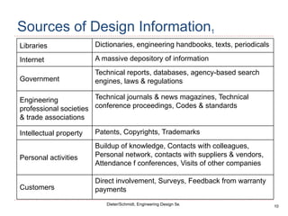
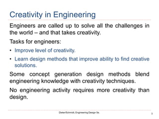
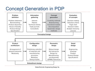
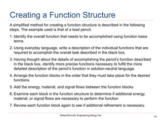
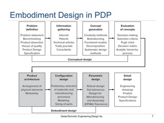
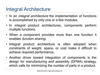
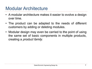
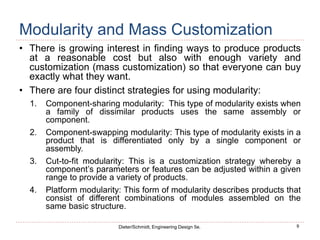
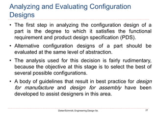
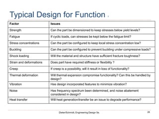
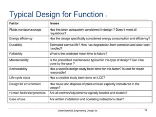
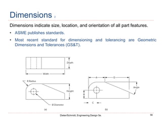
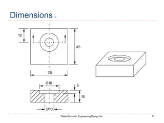
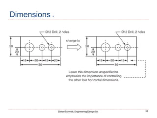
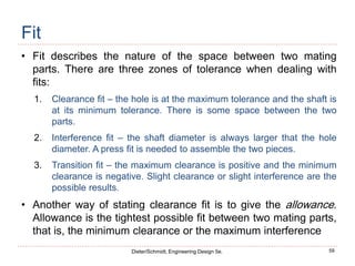
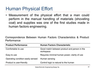
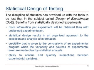
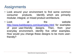
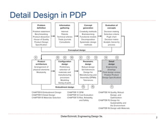
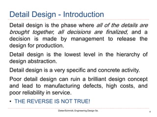
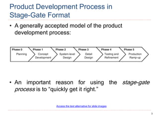
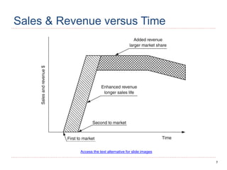
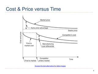
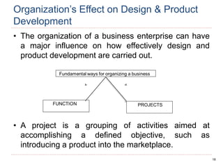
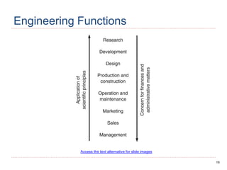
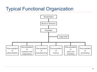
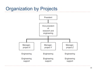
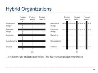
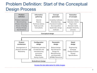
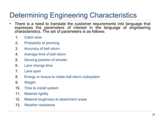
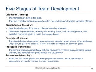
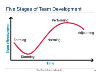
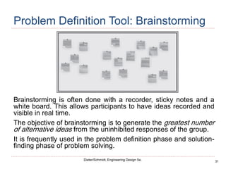
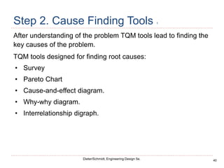
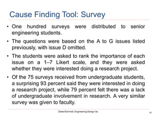
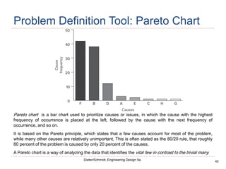
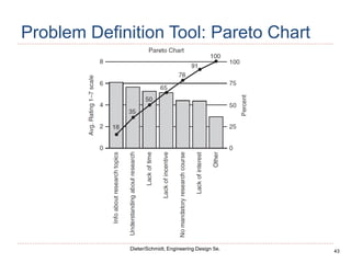
The key stages of the product development process are conceptual design, system-level design, detail design, testing and refinement, and production ramp-up. Success depends on the product's quality, cost, development costs, and time to market. Products can be static or dynamic depending on how often they change. Development can be market pull, driven by customer needs, or technology push, applying new technologies. Organizational structure, such as functional, project-based, or concurrent engineering teams, affects design and development effectiveness.


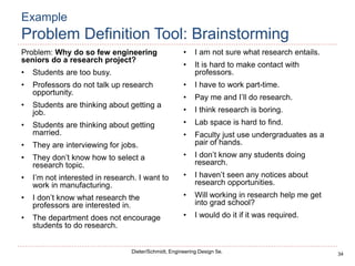
![36
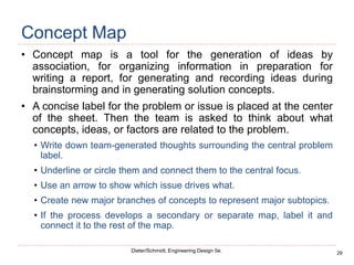
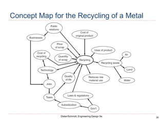
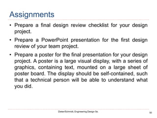
Dieter/Schmidt, Engineering Design 5e.
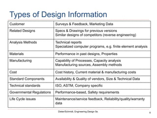
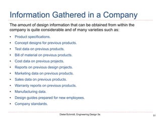
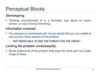
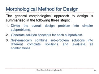
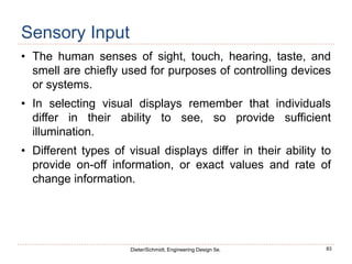
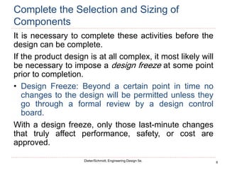
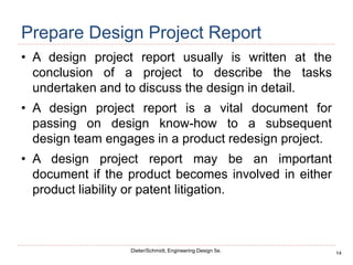
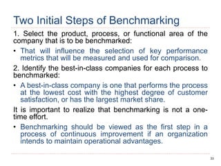
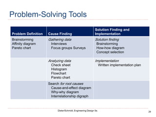
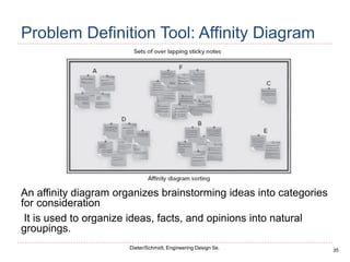
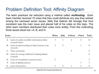
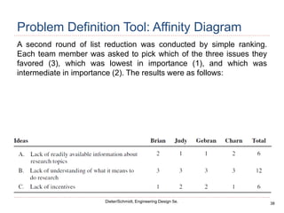
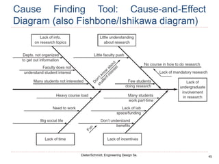
Problem Definition Tool: Affinity Diagram
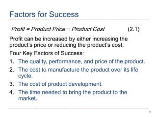
Time constraints
• Students are too busy.
• Students are interviewing for jobs.
• I have to work part-time.
Faculty issues
• Professors don’t talk up research
opportunities.
• The department does not encourage
students to do research.
• It is hard to make contact with professors.
• Faculty just use undergraduates as a pair of
hands.
Lack of interest
• Students are thinking about getting a job.
• [They are thinking about getting married.]
• I’m not interested in research. I want to work
in manufacturing.
• [Pay me and I’ll do research.]
• I think research is boring.
• I would do it if it was required.
Lack of information
• They don’t know how to select a research
topic.
• I don’t know what research the professors
are interested in.
• I’m not sure what research entails.
• I don’t know any students doing research.
• I haven’t seen any notices about research
opportunities.
• Will working in research help me get into
graduate school?
Other
• Lab space is hard to find.](https://image.slidesharecdn.com/productdesign-230115183414-854c2c74/85/Product-design-pdf-173-320.jpg)
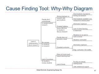
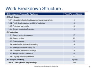
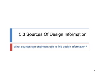
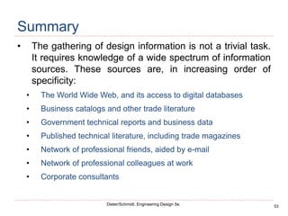
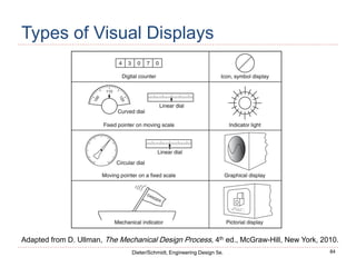
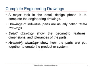
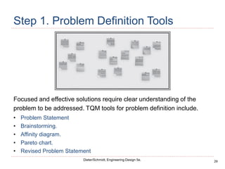
![74
Dieter/Schmidt, Engineering Design 5e.
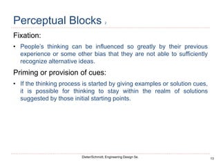
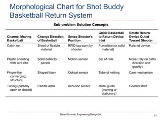
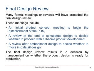
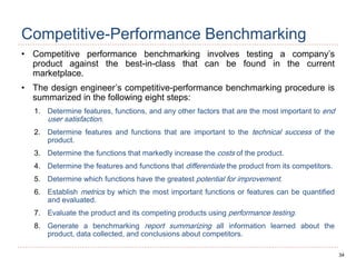
Work Breakdown Structure 1
1.0 Development Process for Appliance Time (Person-Weeks)
1.1 Product specification
1.1.1 Identify customer needs (market surveys, quality function
deployment [QFD])
4
1.1.2 Conduct benchmarking 2
1.1.3 Establish and approve product design specifications (PDS) 2
1.2 Concept generation
1.2.1 Develop alternative concepts 8
1.2.2 Select most suitable concept 2
1.3 Embodiment design
1.3.1 Determine product architecture 2
1.3.2 Complete part configurations 5
1.3.3 Select materials. Analyze for design for manufacture &
assembly
2
1.3.4 Design for robustness for critical to quality (CTQ)
requirements
4
1.3.5 Analyze for reliability and failure with failure modes and effects
analysis (FMEA) and root cause analysis
2](https://image.slidesharecdn.com/productdesign-230115183414-854c2c74/85/Product-design-pdf-211-320.jpg)