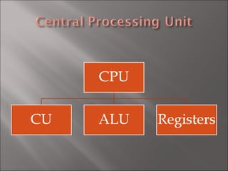
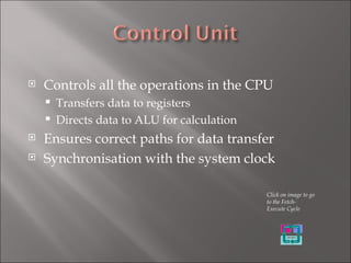
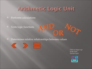
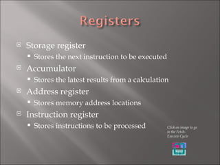
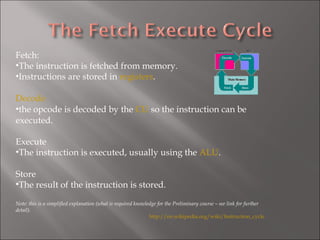
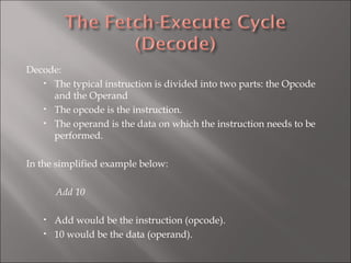
Controls all the operations in the CPU Transfers data to registers Directs data to ALU for calculation  Ensures correct paths for data transfer Synchronisation with the system clock Click on image to go to the Fetch-Execute Cycle
Performs calculations Tests logic functions Determines relative relationships between values Click on image to go to the Fetch-Execute Cycle
Storage register Stores the next instruction to be executed Accumulator Stores the latest results from a calculation Address register Stores memory address locations Instruction register Stores instructions to be processed Click on image to go to the Fetch-Execute Cycle
The system clock is an accurate, very fast electronic timer. The faster the system clock the more instructions per second are executed.
Buses are pathways – separate wires / metallic strips which transport signals (data). http://www.webopedia.com/TERM/b/bus.html
Fetch: The instruction is fetched from memory. Instructions are stored in  registers . Decode the opcode is decoded by the  CU  so the instruction can be executed. Execute The instruction is executed, usually using the  ALU . Store The result of the instruction is stored. Note: this is a simplified explanation (what is required knowledge for the Preliminary course – see link for further detail). http://en.wikipedia.org/wiki/Instruction_cycle
Decode: The typical instruction is divided into two parts: the Opcode and the Operand The opcode is the instruction. The operand is the data on which the instruction needs to be performed. In the simplified example below: Add 10 Add would be the instruction (opcode). 10 would be the data (operand).
More input / output devices Increased processing speed Larger memory (both primary and secondary) which is better for working with sound and graphics

Process And Control Hardware

  • 1.
  • 2.
  • 3.
    Controls all theoperations in the CPU Transfers data to registers Directs data to ALU for calculation Ensures correct paths for data transfer Synchronisation with the system clock Click on image to go to the Fetch-Execute Cycle
  • 4.
    Performs calculations Testslogic functions Determines relative relationships between values Click on image to go to the Fetch-Execute Cycle
  • 5.
    Storage register Storesthe next instruction to be executed Accumulator Stores the latest results from a calculation Address register Stores memory address locations Instruction register Stores instructions to be processed Click on image to go to the Fetch-Execute Cycle
  • 6.
    The system clockis an accurate, very fast electronic timer. The faster the system clock the more instructions per second are executed.
  • 7.
    Buses are pathways– separate wires / metallic strips which transport signals (data). http://www.webopedia.com/TERM/b/bus.html
  • 8.
    Fetch: The instructionis fetched from memory. Instructions are stored in registers . Decode the opcode is decoded by the CU so the instruction can be executed. Execute The instruction is executed, usually using the ALU . Store The result of the instruction is stored. Note: this is a simplified explanation (what is required knowledge for the Preliminary course – see link for further detail). http://en.wikipedia.org/wiki/Instruction_cycle
  • 9.
    Decode: The typicalinstruction is divided into two parts: the Opcode and the Operand The opcode is the instruction. The operand is the data on which the instruction needs to be performed. In the simplified example below: Add 10 Add would be the instruction (opcode). 10 would be the data (operand).
  • 10.
    More input /output devices Increased processing speed Larger memory (both primary and secondary) which is better for working with sound and graphics