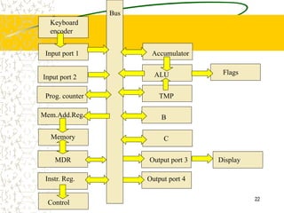
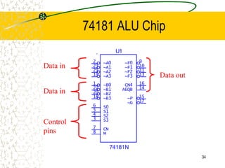
SlideShare a Scribd company logo
1 of 35
1
Microcode
Source: Digital Computer Electronics
(Malvino and Brown)
2
Micro-code
Micro-code is the instructions at the lowest level,
closest to the hardware.
Any higher-level instructions (including
assembly/machine language) must be converted
to a lower level.
A single machine-language instruction (like Load
Accumulator A) typically consists of several
micro-code instructions.
3
Where is microcode stored?
It used to literally be wired in (hence the term “hard
wired”).
Typically it stored in ROM.
If the code is stored in EEPROM, it can be changed;
this is known as microprogramming.
But this is something one does on a rare occasion.
Sometimes referred to as “firmware,” an intermediate
between software and hardware.
4
Machine language
A level above micro-code.
The instructions are numbers, which really are
the addresses of the micro-code instruction in
ROM.
Mnemonic version of machine language is called
assembly language.
5
Assembly is a mnemonic
6
Getting down to hardware’s level
High level programs are translated into assembly
language or machine language by a compiler.
Assembly language programs are translated into
machine language by an assembler.
Each processor has its own unique machine
language. Thus code must be rewritten or at
least recompiled to run on different processor
(different hardware).
7
A simple design
Next we will show a computer design that uses
the basic “bus architecture”
A bus is a basically just wires through which data
travels from one part of a computer to another.
– Usually it’s implied the path is shared by a number of
parts.
– (One also talks about buses in networks.)
8
Input port 1 Accumulator
ALU Flags
Input port 2
Prog. counter
Mem.Add.Reg.
Memory
MDR
Instr. Reg.
Control
C
B
TMP
Output port 3
Output port 4
Display
Keyboard
encoder
Bus
9
Input ports
Keyboard encoder: converts key pressed into
corresponding string of bits (ASCII)
Input port 1: where keyboard data is entered,
usually contains some memory (a buffer) where
data is held until the processor is ready for it
Input port 2: where non-keyboard data is entered
10
Program counter
The program counter points to the current line of
the program (which is stored in memory)
This design shows arrows connecting the “PC”
to and from the bus, why?
– If the next instruction to be executed is not the next
line of code in memory, such as
• If
• Loops
• Subroutines, functions, etc.
11
MAR, MDR and Memory
MAR (Memory Address Register) holds the
address of the memory location being read from
or written to
– Not necessarily same as program counter
Memory (RAM): the place where data and
instructions are stored
MDR (Memory Data Register) holds the data
that is being read from or written to memory
– Bi-directional connection to bus for reading and
writing
12
Instruction Register
Instruction register holds the instruction that is
currently being executed.
A given line of assembly or machine language
code involves several micro-code instructions,
the instruction register holds onto the instruction
until all of the micro-instruction steps are
completed
13
Controller/Sequencer
Executes the program at the lowest level.
Sends signals to the control pins of all the devices
involved.
These lowest level instructions are in ROM.
Each assembly-level instruction has a numerical
counterpart (machine language); the numerical
counterpart is the address of the microcode for that
instruction stored in ROM.
Not shown, controller connects to everything.
14
Accumulator and ALU
Accumulator: register used in conjunction with
the ALU.
Data upon which arithmetic or logic operations
will eventually be performed is stored here; also
the results of these are stored here.
ALU (Arithmetic Logic Unit) where operations
that change the data (as opposed to just moving
it around) are done.
15
Flags
Flags are output from the ALU that are distinct
from data (data output goes to Acc. A)
For example,
– A carry from an addition
– An indication of overflow
• These are needed for program control or to indicate
possible errors
– The result of a logical comparison (<, >, =)
• These are needed for control (ifs, loops, etc)
16
TMP, B and C
TMP is the other register used in conjunction
with the ALU; the distinction is that answers are
generally sent to Accumulator A.
B and C are additional registers used for holding
data temporarily.
– They allow additional flexibility and reduce the
amount that must be written to memory.
17
Output ports
Output port a connection to the “outside world”
– Usually includes a buffer
– This design has to one for displayed output and a
second for other output (e.g. storage)
18
Micro-code
Let us now examine the steps involved in the
assembly (machine language) instruction Load
Accumulator A
19
What do you mean by Load
There are different types of Loads
– Load
• Instruction and address
• Associated data is the address of data that is to be put in Acc. A
– Load immediate
• Instruction and data
• Associated data is actual data to be sent directly to Acc. A
– Load indirect
• Instruction and address of address
• Associated data is an address. Found at that address is another
address. Then at that second address is the data to be placed in Acc.
A.
20
Fetch Cycle
Address State: the value of the program
counter (which recall is the address of line of the
program to be performed) is put into memory
address register.
Increment State: the program counter is
incremented, getting it ready for the next time.
Memory State: the current line of the program is
put into instruction register (so Control knows
what to do).
21
Execution cycle (Load Acc. A)
The remaining steps depend on the specific instruction
and are collectively known as the execution cycle.
Recall the instruction consisted of a load command and
an address. A copy of the address is now taken over
to the memory address register.
The value at that address is loaded into Accumulator A.
For the load command, there is no activity during the
sixth step. It is known as a "no operation" step (a "no
op" or "nop").
22
Input port 1 Accumulator
ALU Flags
Input port 2
Prog. counter
Mem.Add.Reg.
Memory
MDR
Instr. Reg.
Control
C
B
TMP
Output port 3
Output port 4
Display
Keyboard
encoder
Bus
23
Data Movement
Many of the micro-code steps involve moving
data and addresses to various locations
(registers, memory locations, etc.).
The information is often, but not always, sent
over the bus.
So information must be put on and taken from
the bus.
24
Load and Enable
With memory, one talks about reading and
writing.
With registers and the bus, one talks about
enabling and loading.
Enabling: placing a value from a register on the
bus.
Loading: placing a value from the bus into a
register.
25
Register Control pins
A register that takes values off of the bus (e.g.
the Memory Address Register, MAR) will need a
“load” control pin
– It does not always take the value on the bus, instead
it takes the current value on the bus when the load
pin is “activated”
• “Active high”means the action is performed when the pin
is high
• “Active low” means the action is performed when the pin
is low
26
The clock pin
The clock is another control pin (sometimes
called a timing pin) which determines when a
register takes the value on the bus
The load input determines if the register takes
the value
The clock input determines when the register
takes the value
27
The clock
A binary clock: 10101010101010101010
Each cycle (01) should take the same amount of time
(the time for a cycle: the period)
The number of cycles in a second is called the
frequency
“on the edge:” many registers load on the clock’s edge
– Positive edge: as 0 goes to 1
– Negative edge: as 1 goes to 0
28
Enable
The reverse of a load is an enable, this is when
a device places a value on the bus
A register that places values on the bus (e.g. the
buffer associated with an input port) must have
an “enable” control pin
Again enabling may be active high or active low
29
“Only one bus driver”
Only one item can place its value on the bus (“drive the
bus”) at a time. WHY?
– Suppose two items drive the bus and that they have different
values
– Then there would be a direct connection (the bus is
essentially just wire) between a high voltage and a low
voltage
– Since wire offers little resistance, there would be a very large
current – a.k.a. a short
• Large currents destroy digital circuits
30
Three-State logic
If a device is not driving the bus, it must be
effectively disconnected from the bus
– Otherwise the short problem
Thus we need three-state logic
– High
– Low
– Disconnected
31
Tri-State buffer
“Disconnecting” all devices except the “bus
driver” from the bus is done with tri-state buffers
These are not shown in our diagram and are
distinct from chips
Thus we won’t find the kind of “enable” control
pins discussed here on chips
32
Other control pins
Items involved in data manipulation (as opposed
to simply data movement) will require additional
control pins
– For example, the program counter needs to be
incremented
Thus additional control pins are required
– These pins are sometimes also referred to as
“enable” pins, as they enable a particular action
33
ALU control
The primary data manipulator is the ALU
The 74181 is a simple ALU
It has an M select to choose between logic and
arithmetic functions (M)
It has a set of S selects (S0, S1, S2, S3) to
choose among the various functions of that type
34
74181 ALU Chip
U1
74181N
~A0
2
~B0
1
M
8
CN
7
S0
6
~A1
23
~B1
22
~A2
21
~B2
20
~A3
19
~B3
18
S1
5
S3
3
S2
4
~G 17
~P 15
CN4 16
AEQB 14
~F1 10
~F3 13
~F2 11
~F0 9
Data in
Data in
Control
pins
Data out
35
Micro-code is
Micro-code is 1’s and 0’s stored in ROM
The ROM output is connected to control pins
For example, one micro-code instruction is to
take the value from the program counter to the
memory address register
– So send active signals to “enable the PC” and “load
the MAR”

More Related Content

Similar to Basic_Introduction_to_Microcontroller.ppt

Computer organisation Module 1.ppt
Computer organisation Module 1.pptComputer organisation Module 1.ppt
Computer organisation Module 1.pptSoulReaper21
 
Microcontroller
MicrocontrollerMicrocontroller
MicrocontrollerSpitiq
 
Bca examination 2016 csa
Bca examination 2016 csaBca examination 2016 csa
Bca examination 2016 csaAnjaan Gajendra
 
Introduction to Operating Systems
 Introduction to Operating Systems Introduction to Operating Systems
Introduction to Operating SystemsJérôme Kehrli
 
4bit pc report[cse 08-section-b2_group-02]
4bit pc report[cse 08-section-b2_group-02]4bit pc report[cse 08-section-b2_group-02]
4bit pc report[cse 08-section-b2_group-02]shibbirtanvin
 
4bit PC report
4bit PC report4bit PC report
4bit PC reporttanvin
 
Microprocessor and microcontroller
Microprocessor and microcontrollerMicroprocessor and microcontroller
Microprocessor and microcontrollerRavinder Singla
 
Computer Organization : CPU, Memory and I/O organization
Computer Organization : CPU, Memory and I/O organizationComputer Organization : CPU, Memory and I/O organization
Computer Organization : CPU, Memory and I/O organizationAmrutaMehata
 
Microprocessor & Interfacing (Part-2) By Er. Swapnil V. Kaware
Microprocessor & Interfacing (Part-2) By Er. Swapnil V. KawareMicroprocessor & Interfacing (Part-2) By Er. Swapnil V. Kaware
Microprocessor & Interfacing (Part-2) By Er. Swapnil V. KawareProf. Swapnil V. Kaware
 
Addressing modes (detailed data path)
Addressing modes (detailed data path)Addressing modes (detailed data path)
Addressing modes (detailed data path)Mahesh Kumar Attri
 
Microprocessors and microcontrollers
Microprocessors and microcontrollersMicroprocessors and microcontrollers
Microprocessors and microcontrollersgomathy S
 
Computer System Architecture - Computer System Architecture
Computer System Architecture - Computer System ArchitectureComputer System Architecture - Computer System Architecture
Computer System Architecture - Computer System Architecturessusera1e32a1
 
Bca examination 2015 csa
Bca examination 2015 csaBca examination 2015 csa
Bca examination 2015 csaAnjaan Gajendra
 
4th sem,(cs is),computer org unit-7
4th sem,(cs is),computer org unit-74th sem,(cs is),computer org unit-7
4th sem,(cs is),computer org unit-7Sujay pai
 
Chapter 4 the processor
Chapter 4 the processorChapter 4 the processor
Chapter 4 the processors9007912
 
Bindura university of science education
Bindura university of science educationBindura university of science education
Bindura university of science educationInnocent Tauzeni
 
8085 microprocessor
8085 microprocessor8085 microprocessor
8085 microprocessorAnuja Gunale
 

Similar to Basic_Introduction_to_Microcontroller.ppt (20)

Computer organisation Module 1.ppt
Computer organisation Module 1.pptComputer organisation Module 1.ppt
Computer organisation Module 1.ppt
 
Microcontroller
MicrocontrollerMicrocontroller
Microcontroller
 
Bca examination 2016 csa
Bca examination 2016 csaBca examination 2016 csa
Bca examination 2016 csa
 
Introduction to Operating Systems
 Introduction to Operating Systems Introduction to Operating Systems
Introduction to Operating Systems
 
4bit pc report[cse 08-section-b2_group-02]
4bit pc report[cse 08-section-b2_group-02]4bit pc report[cse 08-section-b2_group-02]
4bit pc report[cse 08-section-b2_group-02]
 
4bit PC report
4bit PC report4bit PC report
4bit PC report
 
Microprocessor and microcontroller
Microprocessor and microcontrollerMicroprocessor and microcontroller
Microprocessor and microcontroller
 
Computer Organization : CPU, Memory and I/O organization
Computer Organization : CPU, Memory and I/O organizationComputer Organization : CPU, Memory and I/O organization
Computer Organization : CPU, Memory and I/O organization
 
Microprocessor & Interfacing (Part-2) By Er. Swapnil V. Kaware
Microprocessor & Interfacing (Part-2) By Er. Swapnil V. KawareMicroprocessor & Interfacing (Part-2) By Er. Swapnil V. Kaware
Microprocessor & Interfacing (Part-2) By Er. Swapnil V. Kaware
 
Addressing modes (detailed data path)
Addressing modes (detailed data path)Addressing modes (detailed data path)
Addressing modes (detailed data path)
 
Unit 3 The processor
Unit 3 The processorUnit 3 The processor
Unit 3 The processor
 
Microprocessors and microcontrollers
Microprocessors and microcontrollersMicroprocessors and microcontrollers
Microprocessors and microcontrollers
 
Computer System Architecture - Computer System Architecture
Computer System Architecture - Computer System ArchitectureComputer System Architecture - Computer System Architecture
Computer System Architecture - Computer System Architecture
 
Bca examination 2015 csa
Bca examination 2015 csaBca examination 2015 csa
Bca examination 2015 csa
 
4th sem,(cs is),computer org unit-7
4th sem,(cs is),computer org unit-74th sem,(cs is),computer org unit-7
4th sem,(cs is),computer org unit-7
 
Lect11 organization
Lect11 organizationLect11 organization
Lect11 organization
 
THE PROCESSOR
THE PROCESSORTHE PROCESSOR
THE PROCESSOR
 
Chapter 4 the processor
Chapter 4 the processorChapter 4 the processor
Chapter 4 the processor
 
Bindura university of science education
Bindura university of science educationBindura university of science education
Bindura university of science education
 
8085 microprocessor
8085 microprocessor8085 microprocessor
8085 microprocessor
 

Recently uploaded

How to Check CNIC Information Online with Pakdata cf
How to Check CNIC Information Online with Pakdata cfHow to Check CNIC Information Online with Pakdata cf
How to Check CNIC Information Online with Pakdata cfdanishmna97
 
Tales from a Passkey Provider Progress from Awareness to Implementation.pptx
Tales from a Passkey Provider  Progress from Awareness to Implementation.pptxTales from a Passkey Provider  Progress from Awareness to Implementation.pptx
Tales from a Passkey Provider Progress from Awareness to Implementation.pptxFIDO Alliance
 
Design and Development of a Provenance Capture Platform for Data Science
Design and Development of a Provenance Capture Platform for Data ScienceDesign and Development of a Provenance Capture Platform for Data Science
Design and Development of a Provenance Capture Platform for Data SciencePaolo Missier
 
Introduction to use of FHIR Documents in ABDM
Introduction to use of FHIR Documents in ABDMIntroduction to use of FHIR Documents in ABDM
Introduction to use of FHIR Documents in ABDMKumar Satyam
 
Cyber Insurance - RalphGilot - Embry-Riddle Aeronautical University.pptx
Cyber Insurance - RalphGilot - Embry-Riddle Aeronautical University.pptxCyber Insurance - RalphGilot - Embry-Riddle Aeronautical University.pptx
Cyber Insurance - RalphGilot - Embry-Riddle Aeronautical University.pptxMasterG
 
AI in Action: Real World Use Cases by Anitaraj
AI in Action: Real World Use Cases by AnitarajAI in Action: Real World Use Cases by Anitaraj
AI in Action: Real World Use Cases by AnitarajAnitaRaj43
 
State of the Smart Building Startup Landscape 2024!
State of the Smart Building Startup Landscape 2024!State of the Smart Building Startup Landscape 2024!
State of the Smart Building Startup Landscape 2024!Memoori
 
Introduction to FIDO Authentication and Passkeys.pptx
Introduction to FIDO Authentication and Passkeys.pptxIntroduction to FIDO Authentication and Passkeys.pptx
Introduction to FIDO Authentication and Passkeys.pptxFIDO Alliance
 
Navigating the Large Language Model choices_Ravi Daparthi
Navigating the Large Language Model choices_Ravi DaparthiNavigating the Large Language Model choices_Ravi Daparthi
Navigating the Large Language Model choices_Ravi DaparthiRaviKumarDaparthi
 
ERP Contender Series: Acumatica vs. Sage Intacct
ERP Contender Series: Acumatica vs. Sage IntacctERP Contender Series: Acumatica vs. Sage Intacct
ERP Contender Series: Acumatica vs. Sage IntacctBrainSell Technologies
 
AI+A11Y 11MAY2024 HYDERBAD GAAD 2024 - HelloA11Y (11 May 2024)
AI+A11Y 11MAY2024 HYDERBAD GAAD 2024 - HelloA11Y (11 May 2024)AI+A11Y 11MAY2024 HYDERBAD GAAD 2024 - HelloA11Y (11 May 2024)
AI+A11Y 11MAY2024 HYDERBAD GAAD 2024 - HelloA11Y (11 May 2024)Samir Dash
 
How to Check GPS Location with a Live Tracker in Pakistan
How to Check GPS Location with a Live Tracker in PakistanHow to Check GPS Location with a Live Tracker in Pakistan
How to Check GPS Location with a Live Tracker in Pakistandanishmna97
 
Intro to Passkeys and the State of Passwordless.pptx
Intro to Passkeys and the State of Passwordless.pptxIntro to Passkeys and the State of Passwordless.pptx
Intro to Passkeys and the State of Passwordless.pptxFIDO Alliance
 
How we scaled to 80K users by doing nothing!.pdf
How we scaled to 80K users by doing nothing!.pdfHow we scaled to 80K users by doing nothing!.pdf
How we scaled to 80K users by doing nothing!.pdfSrushith Repakula
 
Top 10 CodeIgniter Development Companies
Top 10 CodeIgniter Development CompaniesTop 10 CodeIgniter Development Companies
Top 10 CodeIgniter Development CompaniesTopCSSGallery
 
Event-Driven Architecture Masterclass: Engineering a Robust, High-performance...
Event-Driven Architecture Masterclass: Engineering a Robust, High-performance...Event-Driven Architecture Masterclass: Engineering a Robust, High-performance...
Event-Driven Architecture Masterclass: Engineering a Robust, High-performance...ScyllaDB
 
JohnPollard-hybrid-app-RailsConf2024.pptx
JohnPollard-hybrid-app-RailsConf2024.pptxJohnPollard-hybrid-app-RailsConf2024.pptx
JohnPollard-hybrid-app-RailsConf2024.pptxJohnPollard37
 
Event-Driven Architecture Masterclass: Integrating Distributed Data Stores Ac...
Event-Driven Architecture Masterclass: Integrating Distributed Data Stores Ac...Event-Driven Architecture Masterclass: Integrating Distributed Data Stores Ac...
Event-Driven Architecture Masterclass: Integrating Distributed Data Stores Ac...ScyllaDB
 
TrustArc Webinar - Unified Trust Center for Privacy, Security, Compliance, an...
TrustArc Webinar - Unified Trust Center for Privacy, Security, Compliance, an...TrustArc Webinar - Unified Trust Center for Privacy, Security, Compliance, an...
TrustArc Webinar - Unified Trust Center for Privacy, Security, Compliance, an...TrustArc
 
ChatGPT and Beyond - Elevating DevOps Productivity
ChatGPT and Beyond - Elevating DevOps ProductivityChatGPT and Beyond - Elevating DevOps Productivity
ChatGPT and Beyond - Elevating DevOps ProductivityVictorSzoltysek
 

Recently uploaded (20)

How to Check CNIC Information Online with Pakdata cf
How to Check CNIC Information Online with Pakdata cfHow to Check CNIC Information Online with Pakdata cf
How to Check CNIC Information Online with Pakdata cf
 
Tales from a Passkey Provider Progress from Awareness to Implementation.pptx
Tales from a Passkey Provider  Progress from Awareness to Implementation.pptxTales from a Passkey Provider  Progress from Awareness to Implementation.pptx
Tales from a Passkey Provider Progress from Awareness to Implementation.pptx
 
Design and Development of a Provenance Capture Platform for Data Science
Design and Development of a Provenance Capture Platform for Data ScienceDesign and Development of a Provenance Capture Platform for Data Science
Design and Development of a Provenance Capture Platform for Data Science
 
Introduction to use of FHIR Documents in ABDM
Introduction to use of FHIR Documents in ABDMIntroduction to use of FHIR Documents in ABDM
Introduction to use of FHIR Documents in ABDM
 
Cyber Insurance - RalphGilot - Embry-Riddle Aeronautical University.pptx
Cyber Insurance - RalphGilot - Embry-Riddle Aeronautical University.pptxCyber Insurance - RalphGilot - Embry-Riddle Aeronautical University.pptx
Cyber Insurance - RalphGilot - Embry-Riddle Aeronautical University.pptx
 
AI in Action: Real World Use Cases by Anitaraj
AI in Action: Real World Use Cases by AnitarajAI in Action: Real World Use Cases by Anitaraj
AI in Action: Real World Use Cases by Anitaraj
 
State of the Smart Building Startup Landscape 2024!
State of the Smart Building Startup Landscape 2024!State of the Smart Building Startup Landscape 2024!
State of the Smart Building Startup Landscape 2024!
 
Introduction to FIDO Authentication and Passkeys.pptx
Introduction to FIDO Authentication and Passkeys.pptxIntroduction to FIDO Authentication and Passkeys.pptx
Introduction to FIDO Authentication and Passkeys.pptx
 
Navigating the Large Language Model choices_Ravi Daparthi
Navigating the Large Language Model choices_Ravi DaparthiNavigating the Large Language Model choices_Ravi Daparthi
Navigating the Large Language Model choices_Ravi Daparthi
 
ERP Contender Series: Acumatica vs. Sage Intacct
ERP Contender Series: Acumatica vs. Sage IntacctERP Contender Series: Acumatica vs. Sage Intacct
ERP Contender Series: Acumatica vs. Sage Intacct
 
AI+A11Y 11MAY2024 HYDERBAD GAAD 2024 - HelloA11Y (11 May 2024)
AI+A11Y 11MAY2024 HYDERBAD GAAD 2024 - HelloA11Y (11 May 2024)AI+A11Y 11MAY2024 HYDERBAD GAAD 2024 - HelloA11Y (11 May 2024)
AI+A11Y 11MAY2024 HYDERBAD GAAD 2024 - HelloA11Y (11 May 2024)
 
How to Check GPS Location with a Live Tracker in Pakistan
How to Check GPS Location with a Live Tracker in PakistanHow to Check GPS Location with a Live Tracker in Pakistan
How to Check GPS Location with a Live Tracker in Pakistan
 
Intro to Passkeys and the State of Passwordless.pptx
Intro to Passkeys and the State of Passwordless.pptxIntro to Passkeys and the State of Passwordless.pptx
Intro to Passkeys and the State of Passwordless.pptx
 
How we scaled to 80K users by doing nothing!.pdf
How we scaled to 80K users by doing nothing!.pdfHow we scaled to 80K users by doing nothing!.pdf
How we scaled to 80K users by doing nothing!.pdf
 
Top 10 CodeIgniter Development Companies
Top 10 CodeIgniter Development CompaniesTop 10 CodeIgniter Development Companies
Top 10 CodeIgniter Development Companies
 
Event-Driven Architecture Masterclass: Engineering a Robust, High-performance...
Event-Driven Architecture Masterclass: Engineering a Robust, High-performance...Event-Driven Architecture Masterclass: Engineering a Robust, High-performance...
Event-Driven Architecture Masterclass: Engineering a Robust, High-performance...
 
JohnPollard-hybrid-app-RailsConf2024.pptx
JohnPollard-hybrid-app-RailsConf2024.pptxJohnPollard-hybrid-app-RailsConf2024.pptx
JohnPollard-hybrid-app-RailsConf2024.pptx
 
Event-Driven Architecture Masterclass: Integrating Distributed Data Stores Ac...
Event-Driven Architecture Masterclass: Integrating Distributed Data Stores Ac...Event-Driven Architecture Masterclass: Integrating Distributed Data Stores Ac...
Event-Driven Architecture Masterclass: Integrating Distributed Data Stores Ac...
 
TrustArc Webinar - Unified Trust Center for Privacy, Security, Compliance, an...
TrustArc Webinar - Unified Trust Center for Privacy, Security, Compliance, an...TrustArc Webinar - Unified Trust Center for Privacy, Security, Compliance, an...
TrustArc Webinar - Unified Trust Center for Privacy, Security, Compliance, an...
 
ChatGPT and Beyond - Elevating DevOps Productivity
ChatGPT and Beyond - Elevating DevOps ProductivityChatGPT and Beyond - Elevating DevOps Productivity
ChatGPT and Beyond - Elevating DevOps Productivity
 

Basic_Introduction_to_Microcontroller.ppt

  • 1. 1 Microcode Source: Digital Computer Electronics (Malvino and Brown)
  • 2. 2 Micro-code Micro-code is the instructions at the lowest level, closest to the hardware. Any higher-level instructions (including assembly/machine language) must be converted to a lower level. A single machine-language instruction (like Load Accumulator A) typically consists of several micro-code instructions.
  • 3. 3 Where is microcode stored? It used to literally be wired in (hence the term “hard wired”). Typically it stored in ROM. If the code is stored in EEPROM, it can be changed; this is known as microprogramming. But this is something one does on a rare occasion. Sometimes referred to as “firmware,” an intermediate between software and hardware.
  • 4. 4 Machine language A level above micro-code. The instructions are numbers, which really are the addresses of the micro-code instruction in ROM. Mnemonic version of machine language is called assembly language.
  • 5. 5 Assembly is a mnemonic
  • 6. 6 Getting down to hardware’s level High level programs are translated into assembly language or machine language by a compiler. Assembly language programs are translated into machine language by an assembler. Each processor has its own unique machine language. Thus code must be rewritten or at least recompiled to run on different processor (different hardware).
  • 7. 7 A simple design Next we will show a computer design that uses the basic “bus architecture” A bus is a basically just wires through which data travels from one part of a computer to another. – Usually it’s implied the path is shared by a number of parts. – (One also talks about buses in networks.)
  • 8. 8 Input port 1 Accumulator ALU Flags Input port 2 Prog. counter Mem.Add.Reg. Memory MDR Instr. Reg. Control C B TMP Output port 3 Output port 4 Display Keyboard encoder Bus
  • 9. 9 Input ports Keyboard encoder: converts key pressed into corresponding string of bits (ASCII) Input port 1: where keyboard data is entered, usually contains some memory (a buffer) where data is held until the processor is ready for it Input port 2: where non-keyboard data is entered
  • 10. 10 Program counter The program counter points to the current line of the program (which is stored in memory) This design shows arrows connecting the “PC” to and from the bus, why? – If the next instruction to be executed is not the next line of code in memory, such as • If • Loops • Subroutines, functions, etc.
  • 11. 11 MAR, MDR and Memory MAR (Memory Address Register) holds the address of the memory location being read from or written to – Not necessarily same as program counter Memory (RAM): the place where data and instructions are stored MDR (Memory Data Register) holds the data that is being read from or written to memory – Bi-directional connection to bus for reading and writing
  • 12. 12 Instruction Register Instruction register holds the instruction that is currently being executed. A given line of assembly or machine language code involves several micro-code instructions, the instruction register holds onto the instruction until all of the micro-instruction steps are completed
  • 13. 13 Controller/Sequencer Executes the program at the lowest level. Sends signals to the control pins of all the devices involved. These lowest level instructions are in ROM. Each assembly-level instruction has a numerical counterpart (machine language); the numerical counterpart is the address of the microcode for that instruction stored in ROM. Not shown, controller connects to everything.
  • 14. 14 Accumulator and ALU Accumulator: register used in conjunction with the ALU. Data upon which arithmetic or logic operations will eventually be performed is stored here; also the results of these are stored here. ALU (Arithmetic Logic Unit) where operations that change the data (as opposed to just moving it around) are done.
  • 15. 15 Flags Flags are output from the ALU that are distinct from data (data output goes to Acc. A) For example, – A carry from an addition – An indication of overflow • These are needed for program control or to indicate possible errors – The result of a logical comparison (<, >, =) • These are needed for control (ifs, loops, etc)
  • 16. 16 TMP, B and C TMP is the other register used in conjunction with the ALU; the distinction is that answers are generally sent to Accumulator A. B and C are additional registers used for holding data temporarily. – They allow additional flexibility and reduce the amount that must be written to memory.
  • 17. 17 Output ports Output port a connection to the “outside world” – Usually includes a buffer – This design has to one for displayed output and a second for other output (e.g. storage)
  • 18. 18 Micro-code Let us now examine the steps involved in the assembly (machine language) instruction Load Accumulator A
  • 19. 19 What do you mean by Load There are different types of Loads – Load • Instruction and address • Associated data is the address of data that is to be put in Acc. A – Load immediate • Instruction and data • Associated data is actual data to be sent directly to Acc. A – Load indirect • Instruction and address of address • Associated data is an address. Found at that address is another address. Then at that second address is the data to be placed in Acc. A.
  • 20. 20 Fetch Cycle Address State: the value of the program counter (which recall is the address of line of the program to be performed) is put into memory address register. Increment State: the program counter is incremented, getting it ready for the next time. Memory State: the current line of the program is put into instruction register (so Control knows what to do).
  • 21. 21 Execution cycle (Load Acc. A) The remaining steps depend on the specific instruction and are collectively known as the execution cycle. Recall the instruction consisted of a load command and an address. A copy of the address is now taken over to the memory address register. The value at that address is loaded into Accumulator A. For the load command, there is no activity during the sixth step. It is known as a "no operation" step (a "no op" or "nop").
  • 22. 22 Input port 1 Accumulator ALU Flags Input port 2 Prog. counter Mem.Add.Reg. Memory MDR Instr. Reg. Control C B TMP Output port 3 Output port 4 Display Keyboard encoder Bus
  • 23. 23 Data Movement Many of the micro-code steps involve moving data and addresses to various locations (registers, memory locations, etc.). The information is often, but not always, sent over the bus. So information must be put on and taken from the bus.
  • 24. 24 Load and Enable With memory, one talks about reading and writing. With registers and the bus, one talks about enabling and loading. Enabling: placing a value from a register on the bus. Loading: placing a value from the bus into a register.
  • 25. 25 Register Control pins A register that takes values off of the bus (e.g. the Memory Address Register, MAR) will need a “load” control pin – It does not always take the value on the bus, instead it takes the current value on the bus when the load pin is “activated” • “Active high”means the action is performed when the pin is high • “Active low” means the action is performed when the pin is low
  • 26. 26 The clock pin The clock is another control pin (sometimes called a timing pin) which determines when a register takes the value on the bus The load input determines if the register takes the value The clock input determines when the register takes the value
  • 27. 27 The clock A binary clock: 10101010101010101010 Each cycle (01) should take the same amount of time (the time for a cycle: the period) The number of cycles in a second is called the frequency “on the edge:” many registers load on the clock’s edge – Positive edge: as 0 goes to 1 – Negative edge: as 1 goes to 0
  • 28. 28 Enable The reverse of a load is an enable, this is when a device places a value on the bus A register that places values on the bus (e.g. the buffer associated with an input port) must have an “enable” control pin Again enabling may be active high or active low
  • 29. 29 “Only one bus driver” Only one item can place its value on the bus (“drive the bus”) at a time. WHY? – Suppose two items drive the bus and that they have different values – Then there would be a direct connection (the bus is essentially just wire) between a high voltage and a low voltage – Since wire offers little resistance, there would be a very large current – a.k.a. a short • Large currents destroy digital circuits
  • 30. 30 Three-State logic If a device is not driving the bus, it must be effectively disconnected from the bus – Otherwise the short problem Thus we need three-state logic – High – Low – Disconnected
  • 31. 31 Tri-State buffer “Disconnecting” all devices except the “bus driver” from the bus is done with tri-state buffers These are not shown in our diagram and are distinct from chips Thus we won’t find the kind of “enable” control pins discussed here on chips
  • 32. 32 Other control pins Items involved in data manipulation (as opposed to simply data movement) will require additional control pins – For example, the program counter needs to be incremented Thus additional control pins are required – These pins are sometimes also referred to as “enable” pins, as they enable a particular action
  • 33. 33 ALU control The primary data manipulator is the ALU The 74181 is a simple ALU It has an M select to choose between logic and arithmetic functions (M) It has a set of S selects (S0, S1, S2, S3) to choose among the various functions of that type
  • 34. 34 74181 ALU Chip U1 74181N ~A0 2 ~B0 1 M 8 CN 7 S0 6 ~A1 23 ~B1 22 ~A2 21 ~B2 20 ~A3 19 ~B3 18 S1 5 S3 3 S2 4 ~G 17 ~P 15 CN4 16 AEQB 14 ~F1 10 ~F3 13 ~F2 11 ~F0 9 Data in Data in Control pins Data out
  • 35. 35 Micro-code is Micro-code is 1’s and 0’s stored in ROM The ROM output is connected to control pins For example, one micro-code instruction is to take the value from the program counter to the memory address register – So send active signals to “enable the PC” and “load the MAR”