Presentation - Theunis Bridge - Dynamo BIM
•Download as PPTX, PDF•
3 likes•1,583 views

A new way in bridge design by dynamo BIM Enjoy ! BIM coordinator: stefan.verhoeven@arcadis.com

Recommended
More Related Content
What's hot
What's hot (19)
Viewers also liked
Viewers also liked (14)
Similar to Presentation - Theunis Bridge - Dynamo BIM
Similar to Presentation - Theunis Bridge - Dynamo BIM (20)
Recently uploaded
Recently uploaded (20)
Presentation - Theunis Bridge - Dynamo BIM
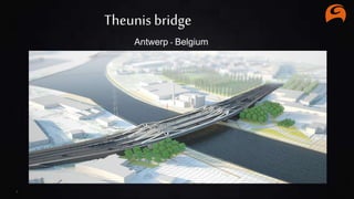
- 1. 1 Theunis bridge Antwerp - Belgium
- 2. 2 The client The engineering offices The architects
- 3. Albert Canal PROJECT INTRODUCTION: In the context of removing the capacity limits for the Albert canal it has been issued that all bridges must beredesigned in order to have a minimum vertical clearance of 9,10m. In the beginning of 2014, 28 bridges of 61 were already executed, 33 other bridges were in progress of design.The ambition is to finish the bridges by 2020. “Theunis” bridge was built around 1960 and is located on the N129 route.It is situated northeast of the cityof Antwerp, in the district “Merksem” and it represents the link between Antwerp-North and Deurne. This urban bridgeis surrounded by industrial and residential areas. 3 GENERAL INTRODUCTION: The Albert canal is the main canal in Belgium. Each year, there are more then 40 million tons of goods transported. The canal connects the port of Antwerp with the industrial area of Liège.
- 5. 5 Architectural context Connection with the district Merksem Transformation of the urban environment Connection with the district Deurne north Connection with the highway and city centre Renewal quay walls Albert canal Connection with the existing bicycle routes Relocation ofthe Theunis bridge Integration existing industrial environment
- 6. 6 Bridge design Functional program: - Tramway with connection to the subway. - Road design 2x2 lanes, speed: 50km/h. - 2 Bicycle - and pedestrian lanes. Dimensions: - Canal widening until approx. 90m. - Bridge span of +/-110 meters. - Bridge width of 50 meters. - Multiple bridges easier to build in phases.
- 7. 7 Environment Impression under the bridge: Transform the old bridge area into an urban social environment. Impression near the bridge: Create an experience for traffic and residents.
- 8. 8 VISUAL PROGRAMMING Theunis Bridge Visual Programming For Bridges After analyzing the complexity of the model and the software tools possibilities, Dynamo and Grasshopper (as a visual programming tools) were chosen in order to generate the bridge in a parametric manner. A collaborative design process was set in place that would ease the process and increase the efficiency
- 9. Interdisciplinary 2016 01 The Architect. Cinema4D / Civil 3D 03 The visual programmers. 02 The Engineers.Nemetscheck SCIA Engineering 04 The 3d Modellers 9
- 10. 10 Top View { Concept} The bridges are curved in longitudinal projection, having also different elevations on bridge ends Longitudinal { Concept } Bridge Architecture Design – Concept Stage The bridges are curved in horizontal projection, the paths of the transversal beams follow a radial distribution between axis 12 and 14, and a parallel distribution towards the ends Sections { Concept} Middle Bridge - Tram Bridge Typical section East And West Bridges Typical Section Sections { Concept }
- 11. Structural Design STRUCTURAL ENGINEERING Structuralanalysis hasbeen performedby the mixBelgian-Romanianteam andthe design software of choicewas SCIA.The physical structures and their componentshavebeendesignedto withstand allnecessaryloadsto ensuresafety, reliabilityand integrity. SCIAcross-section files haverepresentedalsoan entry pointfor the Dynamo generationalgorithm. Cross-section outlineshavebeen made by injectingSCIAcross-sectionfibers valuesdirectly intoDynamo, SCIACrossSection 11
- 12. Civil3D ROAD ENGINEERING Bridge architecture was made in Cinema4D and Civil3D. The provided 3d model was accurate in terms of road outline and bridge main design shape. From Civil 3d we extracted 3d-polylines that were exported as a set of points in CSV. We injected these points in Dynamo to have our main guidelines. CIVIL3DGuideLines Dynamo – XYZ Values 12
- 13. Severalstage wereidentifiedat the beginningof the designprocess anda logicaldesignschema was setin place. The design was intendedto bea multi-disciplinary,multi-user developmentprocess. 01 STEP 02 STEP 03 STEP 05 STEP 04 STEP Externaldata has been read from CSV / EXCEL / TEXT FILES. Generic definitionshave been adapted or newly created to meetparticular conditions Generic definitionshave been placed to adapt to allbridges as a general rule READING INPUT LONGITUDINAL BEAMS AND AXIS CONFIGURING EACH BRIDGE EXPORTING TO REVIT / SAT QUANTITIES 13 06 STEP DRAWINGS
- 14. APPO 3.0 Powerpoint Template.14 VPL – HOW?
- 15. APPO 3.0 Powerpoint Template. Project Structure [Civil exports] [Dyn] [PlatingGeometry] [SciaSectionExport] [xmlgeometry] A python script was written to read the section files (the scope is to fast adopt it to other projects) Cross-Section Dimensions - SCIA READING INPUT All existing data were read and not remade. This kept up certainty with input values Small configuration data and implementing the script in Dynamo and we have the local coordinates of our cross-section. The data for Longitudinal Beams and diagonals were read using these files. Data for Transversal Beams were manually written in the definition 15 Plating Geometry - Thicknesses Civil 3d - Coordinates
- 16. ADDING GENERIC FEATURES Longitudinal Beams and Axis Project Structure [Civil exports] [Dyn] [PlatingGeometry] [SciaSectionExport] [xmlgeometry] A. Skeleton– Creating the longitudinalbeamslayoutof the bridge and preparing the basisfor the next features. Dyn A. Skeleton B. Diagonals C. Diagonal and Beams Surfaces (With Fillets) D. Transversal Beams E. Bicycle Lane F. Stiffeners Using geometric formulasto reach the accuracyrequired (example – using vector cross productto obtaina Z-invariantworking planefor cross-sections) 16 a
- 17. ADDING GENERIC FEATURES The Diagonals B. Diagonals– Creating the longitudinal beamslayoutof the bridge and preparingthe basisfor the next features. Optionto change the degree of diagonals,the height, the start / middle / end segment position 17 b
- 18. ADDING GENERIC FEATURES Plating and the fillets C. Collecting– Getting datafor longitudinalbeams, diagonalsand fillets.Exportingto Revit 18 c
- 19. ADDING GENERICFEATURES Deck,transversalbeams. D. Transversalbeams – Generating transversalbeams, concrete deck andconcrete between beams Transversalbeam data: 19 d
- 20. ADDING GENERIC FEATURES Bicyclelane. E. Bicycle Lane – Generating bicycle lane components (beams, concrete / steel deck plate, longitudinal U-shapestiffeners) 20 e
- 21. ADDING GENERICFEATURES Adding longitudinalstiffeners. F. Stiffeners – Adding some longitudinalstiffeners– and testing several outcome possibilities 21 f
- 22. Local libraryfiles – designed tobe used project independent.These functionsare made to be reused CONFIGURINGEACH BRIDGE Genericdefinitionshavebeen adaptedto particularsituations Externalpythonscriptshave been made tobe used withoutstructure change Using dynamicgeneric programming, dynamo fileshave been used for all3 bridges successfullyafter copying the files to the right folders, changing the folder inputdata pathsand making some particularchanges for the bridges. To change the entry datawe just change the pathto where the datais stored: 22
- 23. EXPORTING TO REVIT Bridge componentshave been exported from Dynamo to Revit andlinkedtogether withother components made in Revit (foundationelements). 23
- 24. APPO 3.0 Powerpoint Template.24 EXPORTING TO EXCEL QUANTITY ESTIMATION a a) Export to excel, data is grouped according to plate position within the overall geometry color coded for faster error check, visual understanding of the thickness distribution
- 25. APPO 3.0 Powerpoint Template.25 EXPORTING TO EXCEL QUANTITY ESTIMATION b b) Rhino Grasshopper – area calculation and separation depending on plate thickness
- 26. APPO 3.0 Powerpoint Template. EXPORTING TO AUTOCAD 26
- 27. 27 How is collaborating on this project: Project Manager: Luc Huysmans BL infrastructure Belgium Project leader: Bart van Zegbroeck & engineers BL infrastructure Belgium BIM engineer & Dynamo specialist: Rami HamatiGEC Romania Civilengineer: Bogdan Gentimir and his team GEC Romania BIMcoordinator: Stefan Verhoeven BL infrastructure Belgium