Download to read offline
![BY:
SUJEET KUMAR JHA [12009]
MANISH KARN [12035]
AHMED RAJA KHAN [12432]
DEPARTMENT OF ELECTRICAL ENGINEERING
KATHMANDU UNIVERSITY](https://image.slidesharecdn.com/0iid3wqatzuw4wqtivtz-signature-a92c992e77f372a53efbc07db762fae7aadc7d06ffb37ecda871f6c150dc0209-poli-170529021615/75/Presentation-on-path-detector-1-2048.jpg)

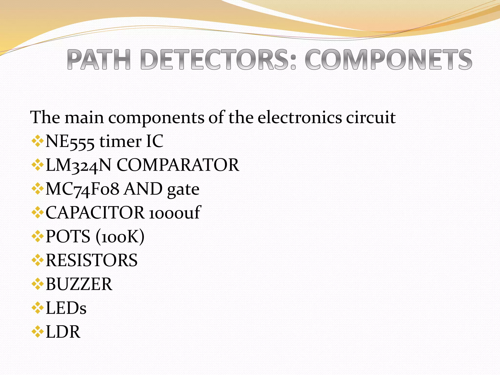
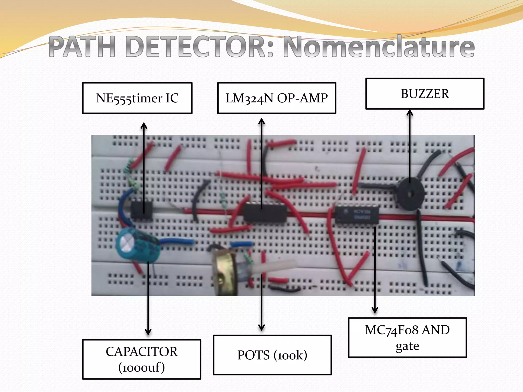
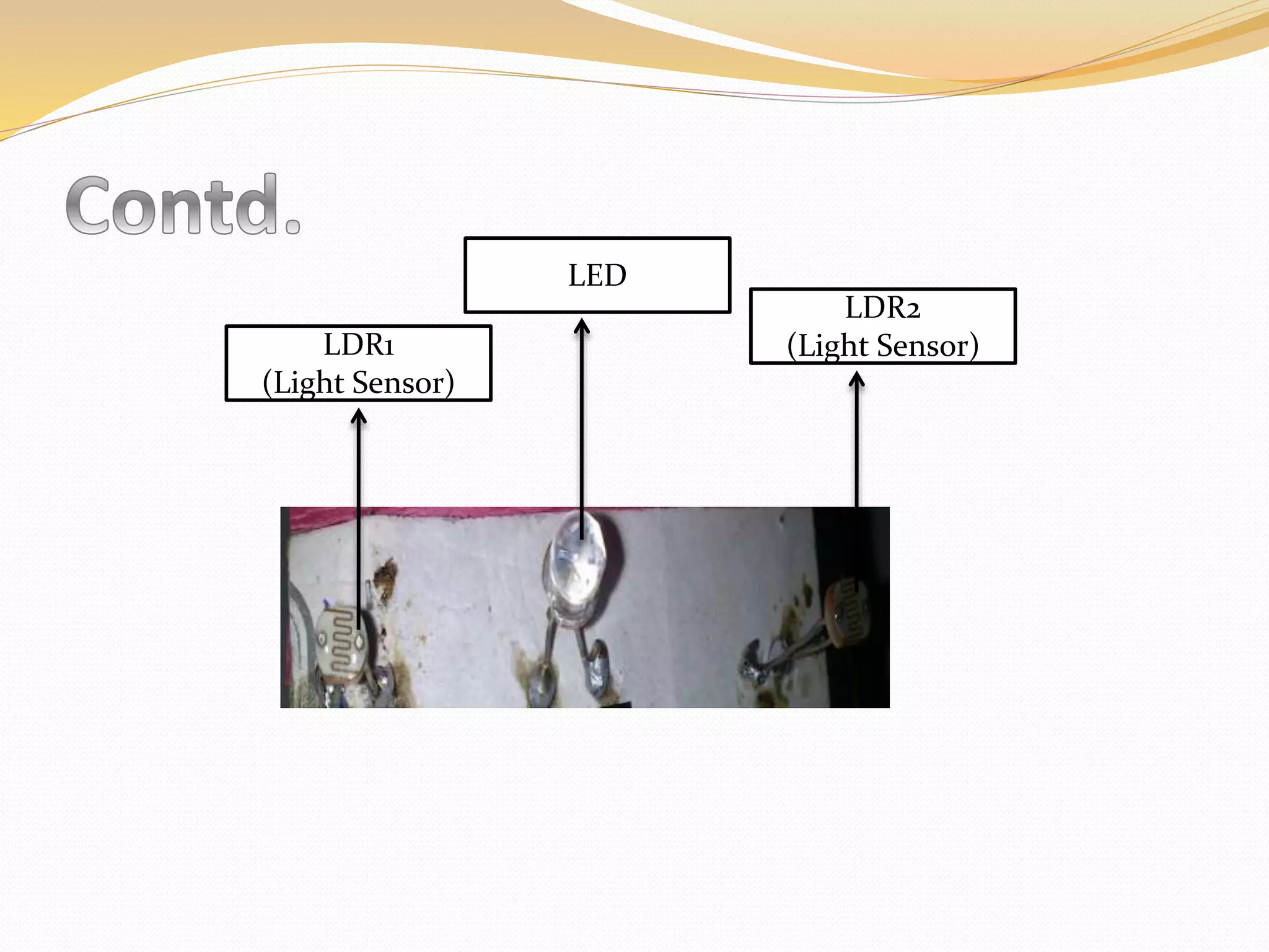
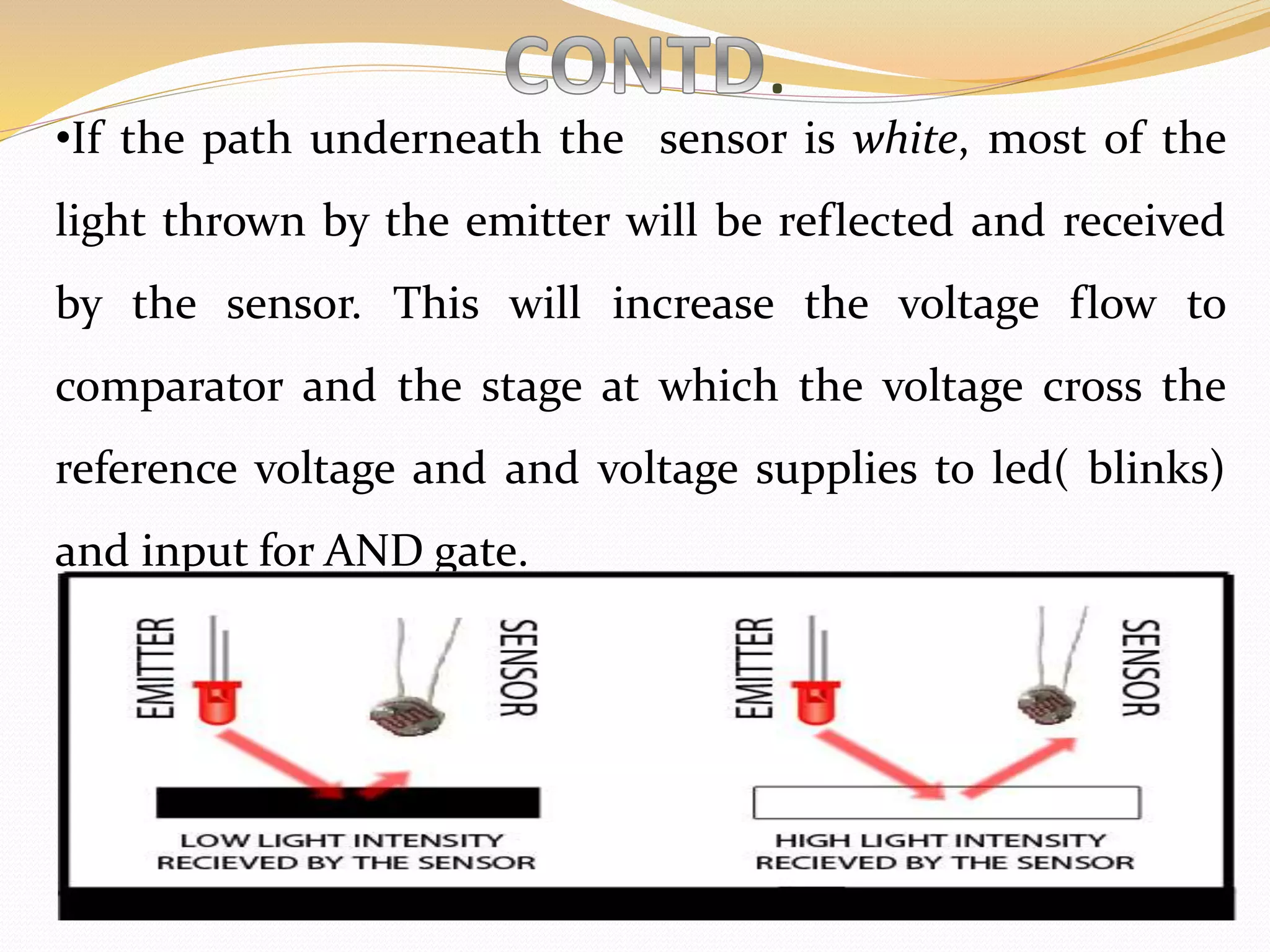

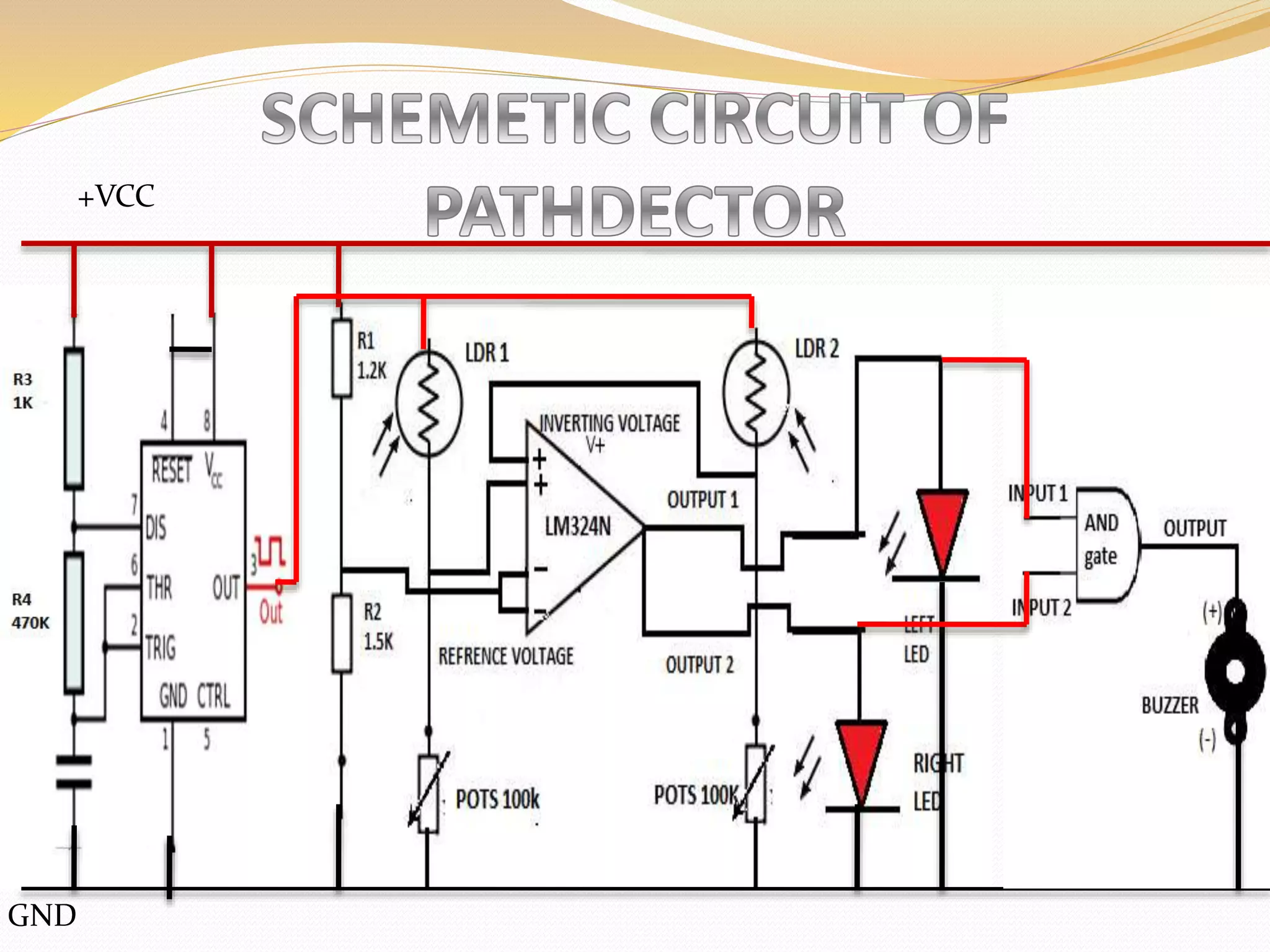
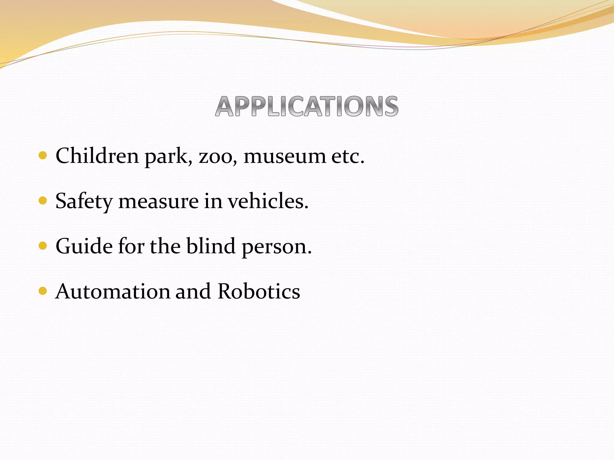


The document describes an electronics circuit designed by students to detect deviations from the correct path and warn users. The main components are a NE555 timer IC, LM324N comparator, MC74F08 AND gate, capacitor, potentiometer, buzzer, LEDs, and light dependent resistors. Light sensors with LEDs and LDRs detect the light reflection of different path surfaces to determine deviations. The circuit was built on a breadboard and tested, with the goal of implementing it on a printed circuit board for use in guiding children, the blind, and for vehicle and robotics applications.