Download as PDF, PPTX


![SURGE PROTEC
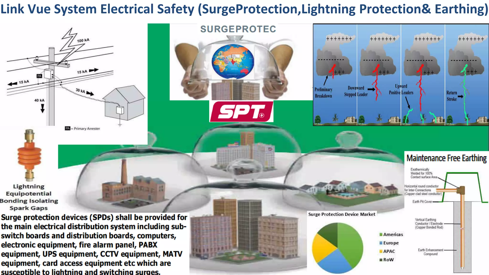
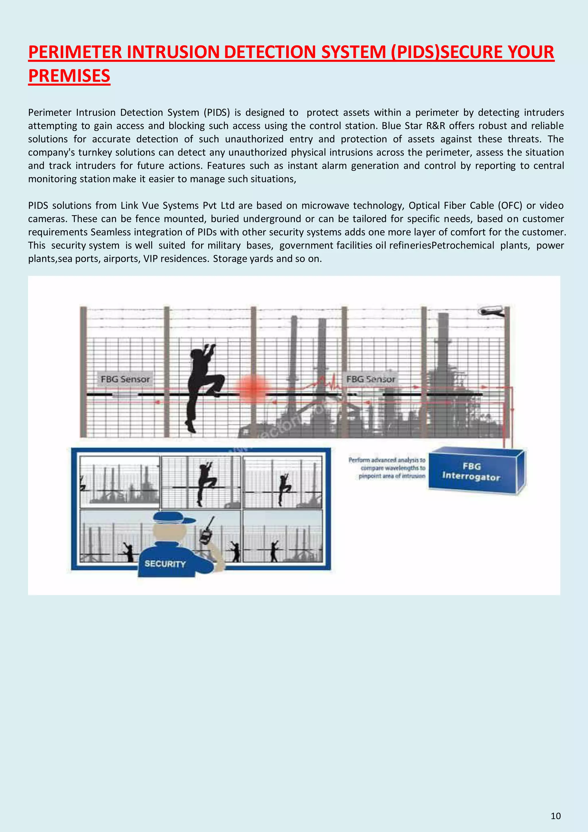
Surge Protection Total Solutions
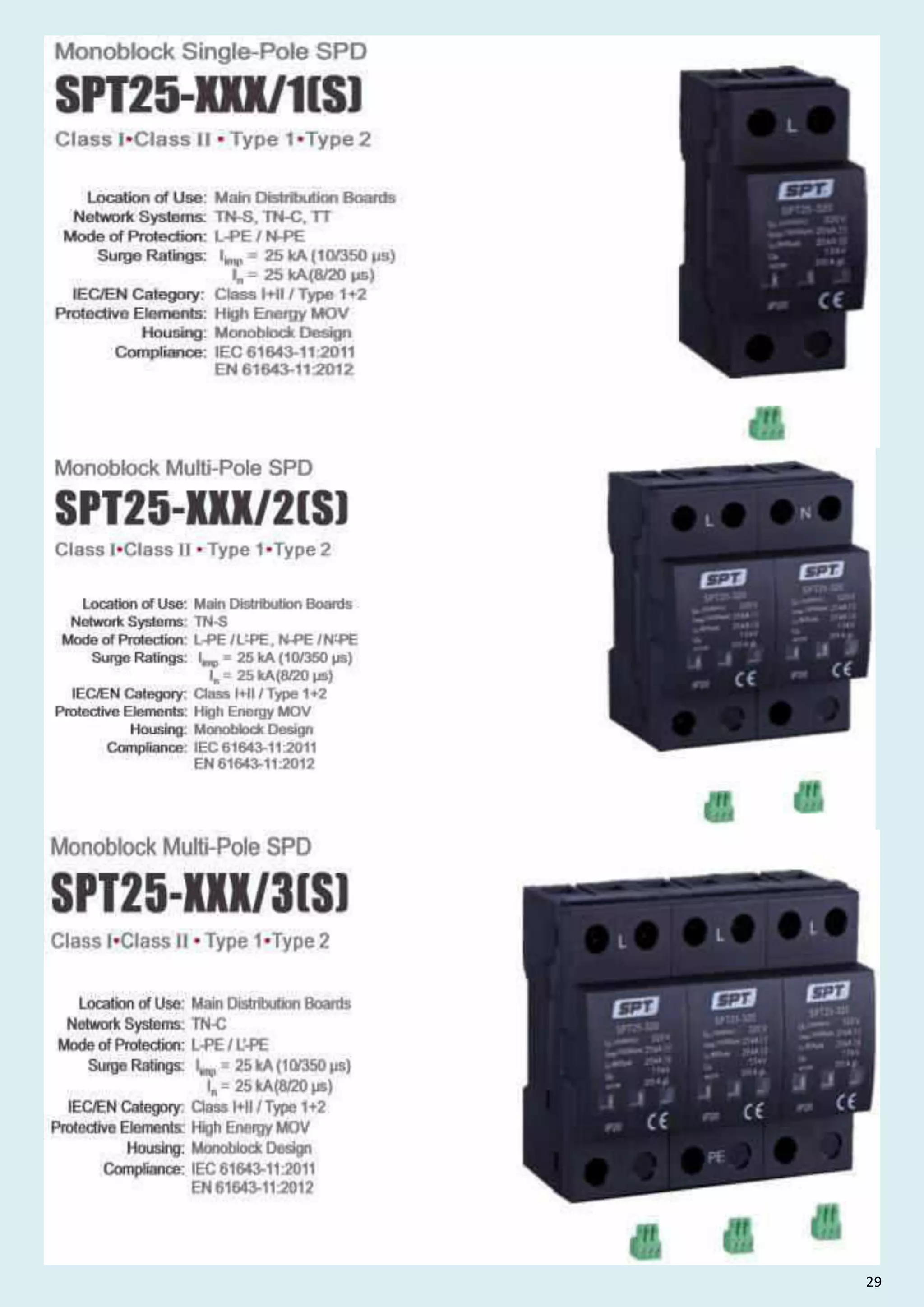
SPT25-XXX/1(S)
Location of Use: Main Distribution Boards
Network Systems: TN-S, TN-C, TT
Mode of Protection: L-PE / N-PE
Surge Ratings: Iimp = 25 kA (10/350 µs)
In = 25 kA(8/20 µs)
IEC/EN Category: Class I+II / Type 1+2
Protective Elements: High Energy MOV
Housing: Monoblock Design
Compliance: IEC 61643-11:2011
EN 61643-11:2012
Technical Data
SPT25-XXX/1(S) 275 320 385 440
IEC Electrical
Nominal AC Voltage (50/60Hz) Uo/ Un 230 V 400 V
Maximum Continuous Operating Voltage (AC) Uc 320 V 385 V 440 V
Nominal Discharge Current (8/20 µs) In
Maximum Discharge Current (8/20 µs) Imax
Impulse Discharge Current (10/350 µs) Iimp 25 kA
100 kA
25 kA
Specific Energy W/R 156 kJ / Ω
230 V
230 V
275 V
120 V
150 V
150
Voltage Protection Level Up 1000 V 1500 V 1600 V 1800 V 2000 V
Response Time tA 25 ns
Back-Up Fuse (max) 315 A gL / gG
Short-Circuit Current Rating (AC) ISCCR 50 kA
TOV Withstand 5s UT 180 V 335 V 580 V
TOV 120min UT 230V 440V
Number of Ports 1
765 V
Mechanical Environmental
Operating Temperature Range Ta -40 ºF to +158 ºF [-40 ºC to +70 ºC]
Permissible Operating Humidity RH 5%...95%
Atmospheric pressure and altitude 80k Pa ... 106k Pa / -500 m ... 2000 m
Terminal Screw Torque Mmax 26.5 Ibf·in [3.0 Nm]
Conductor Cross Section (max) 2 AWG (Solid, Stranded) / 4 AWG (Flexible)
35 mm2
(Solid, Stranded) / 25 mm2 (Flexible)
Mounting 35 mm DIN Rail, EN 60715
Degree of Protection IP 20 (built-in)
Housing Material Thermoplastic: Extinguishing Degree UL 94 V-0
Thermal Protection
Operating State / Fault Indication Green ok / Red defect
Remote Contacts (RC) Optional
RC Switching Capacity AC: 250V / 0.5 A; DC: 250V / 0.1 A; 125 V / 0.2 A; 75 V / 0.5 A
RC Conductor Cross Section (max) 16 AWG (Solid) / 1.5 mm2(Solid)
Order Information
Order Code 275 320 385 440
SPT25-XXX/1
(with remote contacts)
Yes
SPT25-XXX/1S
2515011 2527511 2532011 2538511 2544011
2515012 2527512 2532012 2538512 2544012
335 V
440V
335 V
440V
150
Charge Q 12.5 As
01
Monoblock Single-Pole SPD
Class I Class II Type 1 Type 2
• • •
www.surgeprotec.com](https://image.slidesharecdn.com/buildingautomationnetworkingcommunicationpresentationbylvs2022-220423035623/75/Building-Automation-Networking-Communication-Presentation-by-LVS-2022-pdf-143-2048.jpg)
![RoHS
SPT25-XXX/1(S)
02
Dimensions Packaging
Dimensions Packaging
SPT25-XXX/1(S) 150 275 320 385 440
Single Unit DIN 43880 Dimension 1 CTN
Packaging Dimensions (H x W x L) [260 × 230 × 320 mm]
Minimum Order Quantity 42 Units
Legend
Internal Configuration
L
N
Protective Earth
S Signalling Contacts Optional
Line
Neutral
PE
Connection Diagram
www.surgeprotec.com](https://image.slidesharecdn.com/buildingautomationnetworkingcommunicationpresentationbylvs2022-220423035623/75/Building-Automation-Networking-Communication-Presentation-by-LVS-2022-pdf-144-2048.jpg)
![SPT25-XXX/2(S)
Location of Use: Main Distribution Boards
Network Systems: TN-S
Mode of Protection: L-PE / , N-PE /
L-PE N-PE
′ ′
Surge Ratings: Iimp = 25 kA (10/350 µs)
In = 25 kA(8/20 µs)
IEC/EN Category: Class I+II / Type 1+2
Protective Elements: High Energy MOV
Housing: Monoblock Design
Compliance: IEC 61643-11:2011
EN 61643-11:2012
Technical Data
SPT25-XXX/2(S) 275 320 385 440
150
SURGE PROTEC
Surge Protection Total Solutions
03
Monoblock Multi-Pole SPD
Class I Class II Type 1 Type 2
• • •
www.surgeprotec.com
IEC Electrical
Nominal AC Voltage (50/60Hz) 230 V 400 V
Maximum Continuous Operating Voltage (AC) 320 V 385 V 440 V
Nominal Discharge Current (8/20 µs)
Maximum Discharge Current (8/20 µs)
Impulse Discharge Current (10/350 µs) 25 kA
100 kA
25 kA
Specific Energy 156 kJ / Ω
230 V
230 V
275 V
120 V
150 V
Voltage Protection Level
Response Time 25 ns
Back-Up Fuse (max) 315 A gL / gG
Short-Circuit Current Rating (AC) 50 kA
TOV Withstand 5s 180 V 335 V 580 V
TOV 120min 230 V 440 V
Number of Ports 1
765 V
Mechanical Environmental
Operating Temperature Range -40 ºF to +158 ºF [-40 ºC to +70 ºC]
Permissible Operating Humidity 5%...95%
Atmospheric pressure and altitude 80k Pa ... 106k Pa / -500 m ... 2000 m
Terminal Screw Torque 26.5 Ibf·in [3.0 Nm]
Conductor Cross Section (max) 2 AWG (Solid, Stranded) / 4 AWG (Flexible)
35 mm2 (Solid, Stranded) / 25 mm2 (Flexible)
Mounting 35 mm DIN Rail, EN 60715
Degree of Protection IP 20 (built-in)
Housing Material Thermoplastic: Extinguishing Degree UL 94 V-0
Thermal Protection
Operating State / Fault Indication Green ok / Red defect
Remote Contacts (RC) Optional
RC Switching Capacity AC: 250V / 0.5 A;DC: 250V / 0.1 A; 125 V / 0.2 A; 75 V / 0.5 A
RC Conductor Cross Section (max) 16 AWG (Solid) / 1.5 mm2(Solid)
Order Information
Order Code 275 320 385 440
SPT25-XXX/2
Yes
SPT25-XXX/2S(with remote contacts)
2515021 2527521 2532021 2538521 2544021
2515022 2527522 2532022 2538522 2544022
335 V
440 V
335 V
440 V
150
Charge 12.5 As
Total Discharge Current (10/350 µs)
Uo/ Un
Uc
In
Imax
Iimp
W/R
Up
tA
ISCCR
UT
UT
Ta
RH
Mmax
Q
Itotal 50 kA
1000 V 1500 V 1600 V 1800 V 2000 V](https://image.slidesharecdn.com/buildingautomationnetworkingcommunicationpresentationbylvs2022-220423035623/75/Building-Automation-Networking-Communication-Presentation-by-LVS-2022-pdf-145-2048.jpg)
![RoHS
04
Dimensions Packaging
Internal Configuration
Legend
Connection Diagram
www.surgeprotec.com
SPT25-XXX/2(S)
Dimensions Packaging
SPT25-XXX/2(S) 150 275 320 385 440
Single Unit DIN 43880 Dimension 1 CTN
Packaging Dimensions (H x W x L) [260 × 230 × 320 mm]
Minimum Order Quantity 24 Units
L/L
N/N
Protective Earth
S Signalling Contacts Optional
Line
Neutral
PE
′
′](https://image.slidesharecdn.com/buildingautomationnetworkingcommunicationpresentationbylvs2022-220423035623/75/Building-Automation-Networking-Communication-Presentation-by-LVS-2022-pdf-146-2048.jpg)
![IEC Electrical
Nominal AC Voltage (50/60Hz) 230 V 400 V
Maximum Continuous Operating Voltage (AC) 320 V 385 V 440 V
Nominal Discharge Current (8/20 µs)
Maximum Discharge Current (8/20 µs)
Impulse Discharge Current (10/350 µs) 25 kA
100 kA
25 kA
Specific Energy 156 kJ / Ω
230 V
230 V
275 V
120 V
150 V
Voltage Protection Level
Response Time 25 ns
Back-Up Fuse (max) 315 A gL / gG
Short-Circuit Current Rating (AC) 50 kA
TOV Withstand 5s 180 V 335 V 580 V
TOV 120min 230 V 440 V
Number of Ports 1
765 V
Mechanical Environmental
Operating Temperature Range -40 ºF to +158 ºF [-40 ºC to +70 ºC]
Permissible Operating Humidity 5%...95%
Atmospheric pressure and altitude 80k Pa ... 106k Pa / -500 m ... 2000 m
Terminal Screw Torque 26.5 Ibf·in [3.0 Nm]
Conductor Cross Section (max) 2 AWG (Solid, Stranded) / 4 AWG (Flexible)
35 mm2 (Solid, Stranded) / 25 mm2 (Flexible)
Mounting 35 mm DIN Rail, EN 60715
Degree of Protection IP 20 (built-in)
Housing Material Thermoplastic: Extinguishing Degree UL 94 V-0
Thermal Protection
Operating State / Fault Indication Green ok / Red defect
Remote Contacts (RC) Optional
RC Switching Capacity AC: 250V / 0.5 A; DC: 250V / 0.1 A; 125 V / 0.2 A; 75 V / 0.5 A
RC Conductor Cross Section (max) 16 AWG (Solid) / 1.5 mm2(Solid)
Order Information
Order Code 275 320 385 440
SPT25-XXX/3
(with remote contacts)
Yes
SPT25-XXX/3S
2515031 2527531 2532031 2538531 2544031
2515032 2527532 2532032 2538532 2544032
335 V
440 V
335 V
440 V
150
Charge 12.5 As
Total Discharge Current (10/350 µs) 75 kA
1000 V 1500 V 1800 V 2000 V
1600 V
Technical Data
275 320 385 440
150
05
Monoblock Multi-Pole SPD
Class I Class II Type 1 Type 2
• • •
www.surgeprotec.com
Location of Use: Main Distribution Boards
Network Systems: TN-C
Mode of Protection: L-PE / L-PE
′
Surge Ratings: Iimp = 25 kA (10/350 µs)
In = 25 kA(8/20 µs)
IEC/EN Category: Class I+II / Type 1+2
Protective Elements: High Energy MOV
Housing: Monoblock Design
Compliance: IEC 61643-11:2011
EN 61643-11:2012
SPT25-XXX/3(S)
SPT25-XXX/3(S)
SURGE PROTEC
Surge Protection Total Solutions
Uo/ Un
Uc
In
Imax
Iimp
W/R
Up
tA
ISCCR
UT
UT
Ta
RH
Mmax
Q
Itotal](https://image.slidesharecdn.com/buildingautomationnetworkingcommunicationpresentationbylvs2022-220423035623/75/Building-Automation-Networking-Communication-Presentation-by-LVS-2022-pdf-147-2048.jpg)
![RoHS
Protective Earth
S Signalling Contacts Optional
Line
Neutral
PE
L / ′
L
N / ′
N
SPT25-XXX/3(S)
06
Dimensions Packaging
Legend
Internal Configuration
Connection Diagram
www.surgeprotec.com
Dimensions Packaging
SPT25-XXX/3(S) 150 275 320 385 440
Single Unit DIN 43880 Dimension 1 CTN
Packaging Dimensions (H x W x L) [260 × 230 × 320 mm]
Minimum Order Quantity 12 Units](https://image.slidesharecdn.com/buildingautomationnetworkingcommunicationpresentationbylvs2022-220423035623/75/Building-Automation-Networking-Communication-Presentation-by-LVS-2022-pdf-148-2048.jpg)
![Mechanical Environmental
Order Information
Order Code 275 320 385 440
150
Operating Temperature Range Ta -40 ºF to +158 ºF [-40 ºC to +70 ºC]
Permissible Operating Humidity RH 5%...95%
Atmospheric pressure and altitude 80k Pa ... 106k Pa / -500 m ... 2000 m
Terminal Screw Torque Mmax 26.5 Ibf·in [3.0 Nm]
Conductor Cross Section (max) 2 AWG (Solid, Stranded) / 4 AWG (Flexible)
35 mm2(Solid, Stranded) / 25 mm2 (Flexible)
Mounting 35 mm DIN Rail, EN 60715
Degree of Protection IP 20 (built-in)
Housing Material Thermoplastic: Extinguishing Degree UL 94 V-0
Thermal Protection
Operating State / Fault Indication Green ok / Red defect
Remote Contacts (RC) Optional
RC Switching Capacity AC: 250V / 0.5 A;DC: 250V / 0.1 A; 125 V / 0.2 A; 75 V / 0.5 A
RC Conductor Cross Section (max) 16 AWG (Solid) / 1.5 mm2(Solid)
Yes
SPT25-XXX/4
(with remote contacts)
SPT25-XXX/4S
2515041 2527541 2532041 2538541 2544041
2515042 2527542 2532042 2538542 2544042
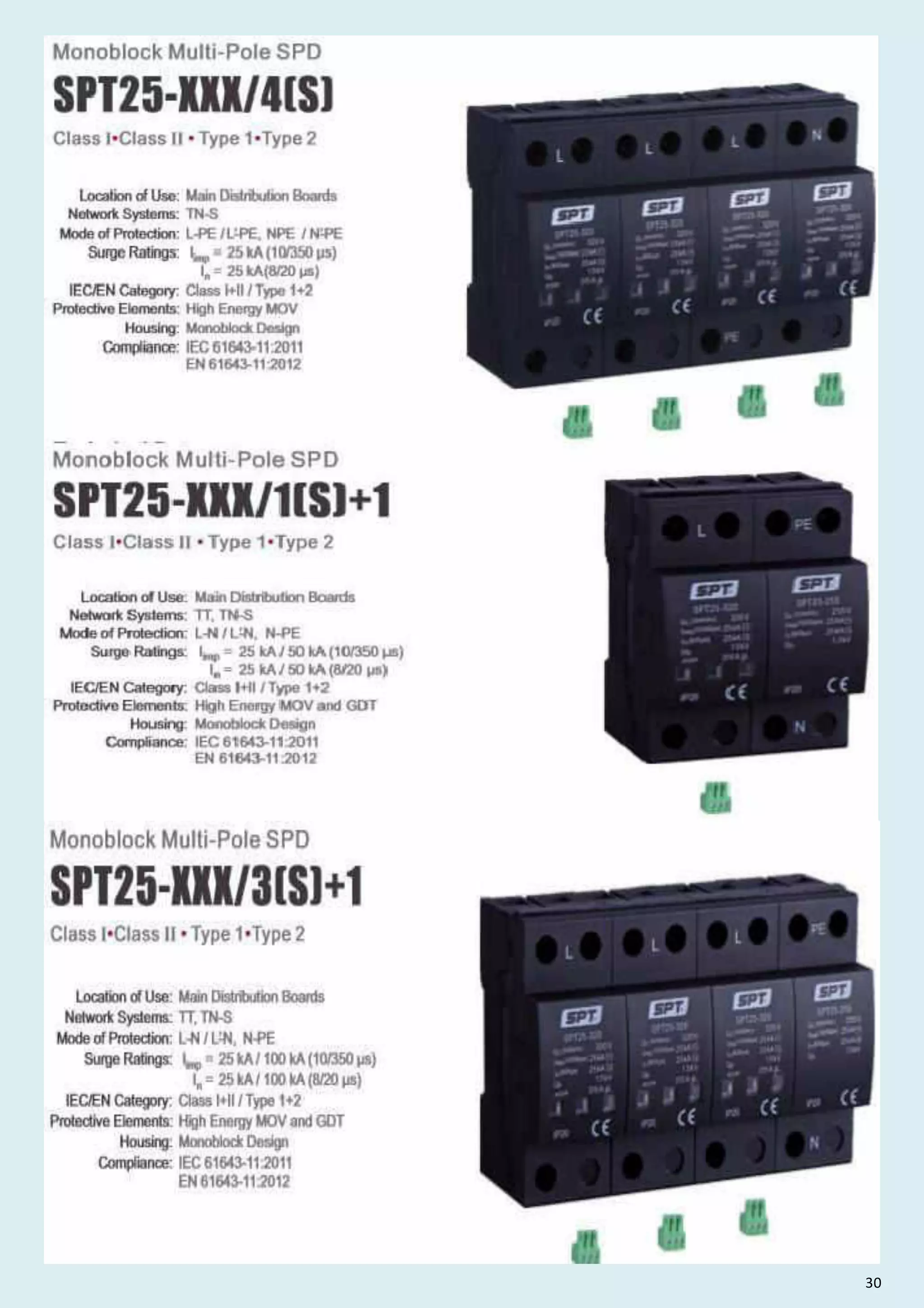
Location of Use: Main Distribution Boards
Network Systems: TN-S
Mode of Protection: L-PE / /
L-PE, - N-PE
′ NPE ′
Surge Ratings: Iimp = 25 kA (10/350 µs)
In = 25 kA(8/20 µs)
IEC/EN Category: Class I+II / Type 1+2
Protective Elements: High Energy MOV
Housing: Monoblock Design
Compliance: IEC 61643-11:2011
EN 61643-11:2012
SURGE PROTEC
Surge Protection Total Solutions
Technical Data
275 320 385 440
IEC Electrical
150
07
Class I Class II Type 1 Type 2
• • •
www.surgeprotec.com
SPT25-XXX/4(S)
Nominal AC Voltage (50/60Hz) Uo/ Un 230 V 400 V
Maximum Continuous Operating Voltage (AC) Uc 320 V 385 V 440 V
Nominal Discharge Current (8/20 µs) In
Maximum Discharge Current (8/20 µs) Imax
Impulse Discharge Current (10/350 µs) Iimp 25 kA
100 kA
25 kA
Specific Energy W/R 156 kJ / Ω
230 V
230 V
275 V
120 V
150 V
Voltage Protection Level Up
Response Time tA 25 ns
Back-Up Fuse (max) 315 A gL / gG
Short-Circuit Current Rating (AC) ISCCR 50 kA
TOV Withstand 5s UT 180 V 335 V 580 V
TOV 120min UT 230 V 440 V
Number of Ports 1
765 V
335 V
440 V
335 V
440 V
Charge Q 12.5 As
Total Discharge Current (10/350 µs) Itotal 100 kA
1000 V 1500 V 1800 V 2000 V
1600 V
Monoblock Multi-Pole SPD
SPT25-XXX/4(S)](https://image.slidesharecdn.com/buildingautomationnetworkingcommunicationpresentationbylvs2022-220423035623/75/Building-Automation-Networking-Communication-Presentation-by-LVS-2022-pdf-149-2048.jpg)
![Protective Earth
S Signalling Contacts Optional
Line
Neutral
PE
L / ′
L
N / ′
N
RoHS
SPT25-XXX/4(S)
08
Dimensions Packaging
Legend
Internal Configuration
Connection Diagram
www.surgeprotec.com
Dimensions Packaging
SPT25-XXX/4(S) 150 275 320 385 440
Single Unit DIN 43880 Dimension 1 CTN
Packaging Dimensions (H x W x L) [260 × 230 × 320 mm]
Minimum Order Quantity 12 Units](https://image.slidesharecdn.com/buildingautomationnetworkingcommunicationpresentationbylvs2022-220423035623/75/Building-Automation-Networking-Communication-Presentation-by-LVS-2022-pdf-150-2048.jpg)
![SPT25-XXX/1(S)+1
SPT25-XXX/1(S)+1
Monoblock Multi-Pole SPD
SURGE PROTEC
Surge Protection Total Solutions
Technical Data
275 320 385
150
Class I Class II Type 1 Type 2
• • •
09 www.surgeprotec.com
Location of Use: Main Distribution Boards
Network Systems: TT, TN-S
Mode of Protection: L-N N-PE
/ L-N,
′
Surge Ratings: Iimp = 25 kA / 50 kA (10/350 µs)
In =
Class I+II / Type 1+2
Protective Elements: High Energy MOV and GDT
Housing:
Compliance: IEC 61643-11:2011
EN 61643-11:2012
IEC/EN Category:
25 kA / 50 kA (8/20 µs)
Monoblock Design
Operating Temperature Range Ta -40 ºF to +158 ºF [-40 ºC to +70 ºC]
Permissible Operating Humidity RH 5%...95%
Terminal Screw Torque Mmax [
26.5 Ibf·in 3.0 Nm]
Conductor Cross Section (max) 2 AWG (Solid, Stranded) / 4 AWG (Flexible)
35 mm2 (Solid, Stranded) / 25 mm2(Flexible)
Mounting 35 mm DIN Rail, EN 60715
Degree of Protection IP 20 (built-in)
Housing Material Thermoplastic: Extinguishing Degree UL 94 V-0
Thermal Protection
Operating State / Fault Indication
Remote Contacts (RC) Optional
RC Switching Capacity
RC Conductor Cross Section (max) 16 AWG (Solid) / 1.5 mm2(Solid)
Atmospheric pressure and altitude 80k Pa ... 106k Pa / -500 m ... 2000 m
Yes
Green ok / Red defect
AC: 250V / 0.5 A;DC: 250V / 0.1 A; 125 V / 0.2 A; 75 V / 0.5 A
Nominal AC Voltage (50/60Hz)
Maximum Continuous Operating Voltage (L - N) Uc
(N - PE) Uc 255 V 255 V 255 V
Nominal Discharge Current (8/20 µs) (L - N) / (N - PE) In 25 kA / 50 kA
Maximum Discharge Current (8/20 µs) (L - N) / (N - PE) Imax 100 kA
Impulse Discharge Current (10/350 µs) (L - N) / (N - PE) Iimp
230 V
230 V
120 V
320 V
275 V
150 V
Specific Energy (L - N) / (N - PE) W/R 156 kJ / Ω / 625 kJ / Ω
Charge (L - N) / (N - PE) Q 12.5 As / 25 As
Voltage Protection Level (L - N) / (N - PE) Up 1000 V/ 1500 V 1500 V/ 1500 V 1600 V/ 1500 V
Follow Current Interrupt Rating (N-PE) Ifi 100 A RMS
Response Time (L - N) / (N - PE) tA 25 ns / 100 ns
Back-Up Fuse (max) 315 A gL / gG
Short-Circuit Current Rating (AC) (L - N) ISCCR 50 kA
TOV Withstand 5s (L - N) UT
TOV 120min (L - N) UT
TOV Withstand 200ms (N - PE) UT 1200 V
Number of Ports 1
180 V 335 V
230 V 440 V
335 V
440 V
25 kA / 50 kA
Total Discharge Current (10/350 µs) Itotal 50 kA
1800 V/ 1500 V
255 V
230 V
385 V
335 V
440 V
IEC Electrical
Mechanical Environmental](https://image.slidesharecdn.com/buildingautomationnetworkingcommunicationpresentationbylvs2022-220423035623/75/Building-Automation-Networking-Communication-Presentation-by-LVS-2022-pdf-151-2048.jpg)
![Order Code 150 275 320 385
SPT25-XXX/1+1
(with remote contacts)
SPT25-XXX/1S+1
2515013
2515014
2527513
2527514
2532013
2532014
2538513
2538514
Order Information
SPT25-XXX/1(S)+1 150 275 320 385 440
Single Unit DIN 43880 Dimension 1 CTN
Packaging Dimensions (H x W x L) [260 × 230 × 320 mm]
Minimum Order Quantity 24 Units
Protective Earth
S Signalling Contacts Optional
Line
Neutral
L / ′
L
N
PE PE
/ ′
RoHS
10
Dimensions Packaging
Dimensions Packaging
Legend
Internal Configuration
Connection Diagram
www.surgeprotec.com
SPT25-XXX/1(S)+1](https://image.slidesharecdn.com/buildingautomationnetworkingcommunicationpresentationbylvs2022-220423035623/75/Building-Automation-Networking-Communication-Presentation-by-LVS-2022-pdf-152-2048.jpg)
![SPT25-XXX/3(S)+1
Monoblock Multi-Pole SPD
Location of Use: Main Distribution Boards
Network Systems: TT, TN-S
Mode of Protection: L-N N-PE
/ L-N,
′
Surge Ratings: Iimp = 25 kA / 100 kA (10/350 µs)
In =
Class I+II / Type 1+2
Protective Elements: High Energy MOV and GDT
Housing:
Compliance: IEC 61643-11:2011
EN 61643-11:2012
IEC/EN Category:
25 kA / 100 kA (8/20 µs)
Monoblock Design
SURGE PROTEC
Surge Protection Total Solutions
SPT25-XXX/3(S)+1
Technical Data
275 320 385
150
Class I Class II Type 1 Type 2
• • •
11 www.surgeprotec.com
Operating Temperature Range Ta -40 ºF to +158 ºF [-40 ºC to +70 ºC]
Permissible Operating Humidity RH 5%...95%
Terminal Screw Torque Mmax [
26.5 Ibf·in 3.0 Nm]
Conductor Cross Section (max) 2 AWG (Solid, Stranded) / 4 AWG (Flexible)
35 mm2 (Solid, Stranded) / 25 mm2(Flexible)
Mounting 35 mm DIN Rail, EN 60715
Degree of Protection IP 20 (built-in)
Housing Material Thermoplastic: Extinguishing Degree UL 94 V-0
Thermal Protection
Operating State / Fault Indication
Remote Contacts (RC) Optional
RC Switching Capacity
RC Conductor Cross Section (max) 16 AWG (Solid) / 1.5 mm2(Solid)
Atmospheric pressure and altitude 80k Pa ... 106k Pa / -500 m ... 2000 m
Yes
Green ok / Red defect
AC: 250V / 0.5 A; DC: 250V / 0.1 A; 125 V / 0.2 A; 75 V / 0.5 A
Nominal AC Voltage (50/60Hz)
Maximum Continuous Operating Voltage (L - N) Uc
(N - PE) Uc 255 V 255 V 255 V
Nominal Discharge Current (8/20 µs) (L - N) / (N - PE) In 25 kA / 100 kA
Maximum Discharge Current (8/20 µs) (L - N) / (N - PE) Imax 100 kA
Impulse Discharge Current (10/350 µs) (L - N) / (N - PE) Iimp
230 V
230 V
120 V
320 V
275 V
150 V
Specific Energy (L - N) / (N - PE) W/R
Charge (L - N) / (N - PE) Q
Voltage Protection Level (L - N) / (N - PE) Up
Follow Current Interrupt Rating (N-PE) Ifi 100 ARMS
Response Time (L - N) / (N - PE) tA 25 ns / 100 ns
Back-Up Fuse (max) 315 A gL / gG
Short-Circuit Current Rating (AC) (L - N) ISCCR 50 kA
TOV Withstand 5s (L - N) UT
TOV 120min (L - N) UT
TOV Withstand 200ms (N - PE) UT 1200 V
Number of Ports 1
180 V 335 V
230 V 440 V
335 V
440 V
25 kA / 100 kA
Total Discharge Current (10/350 µs) Itotal 100 kA
255 V
230 V
385 V
335 V
440 V
156 kJ / Ω / 2.5 M kJ / Ω
12.5 As / 50 As
1000 V/ 1500 V 1500 V/ 1500 V 1800 V/ 1500 V
1600 V/ 1500 V
IEC Electrical
Mechanical Environmental](https://image.slidesharecdn.com/buildingautomationnetworkingcommunicationpresentationbylvs2022-220423035623/75/Building-Automation-Networking-Communication-Presentation-by-LVS-2022-pdf-153-2048.jpg)
![12
www.surgeprotec.com
SPT25-XXX/3(S)+1
Order Code 150 275 320 385
SPT25-XXX/3+1
(with remote contacts)
SPT25-XXX/3S+1
2515033
2515034
2527533
2527534
2532033
2532034
2538533
2538534
Order Information
SPT25-XXX/3(S)+1 150 275 320 385 440
Single Unit DIN 43880 Dimension 1 CTN
Packaging Dimensions (H x W x L) [260 × 230 × 320 mm]
Minimum Order Quantity 12 Units
Protective Earth
S Signalling Contacts Optional
Line
Neutral
L / ′
L
N
PE PE
/ ′
RoHS
Dimensions Packaging
Dimensions Packaging
Legend
Internal Configuration
Connection Diagram](https://image.slidesharecdn.com/buildingautomationnetworkingcommunicationpresentationbylvs2022-220423035623/75/Building-Automation-Networking-Communication-Presentation-by-LVS-2022-pdf-154-2048.jpg)
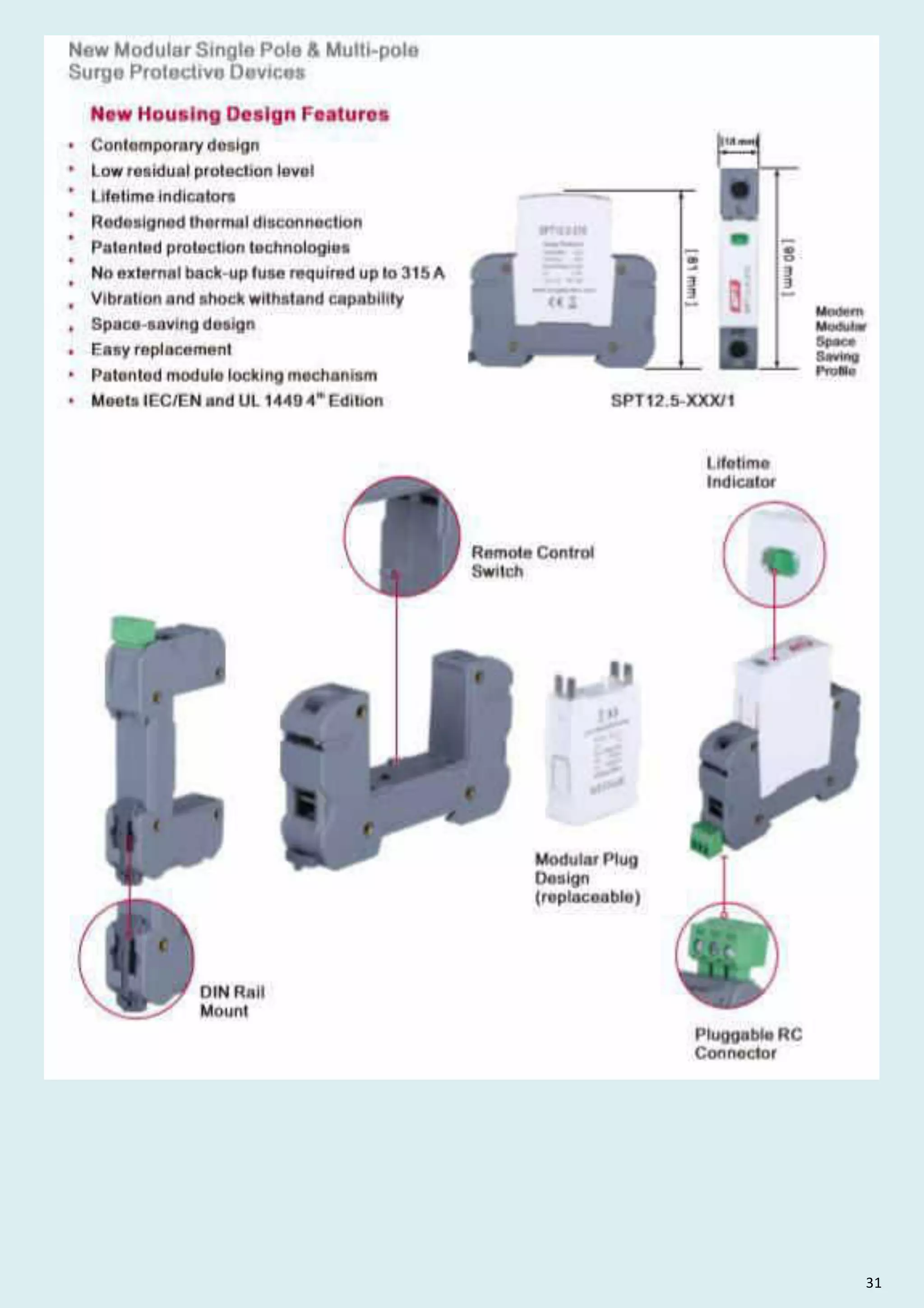
![New Modular Single Pole Multi-pole
Surge Protective Devices
13 www.surgeprotec.com
New Housing Design Features
Contemporary design
Low residual protection level
Lifetime indicators
Redesigned thermal disconnection
Patented protection technologies
No external back-up fuse required up to 315 A
Vibration and shock withstand capability
Space-saving design
Easy replacement
Patented module locking mechanism
th
Meets IEC/EN and UL 1449 4 Edition
Remote Control
Switch
Lifetime
Indicator
Modular Plug
Design
(replaceable)
Pluggable RC
Connector
SURGE PROTEC
Surge Protection Total Solutions
Modern
Modular
Space
Saving
Profile
[18 mm]
[
90
mm
]
[
81
mm
]
SPT12.5-XXX/1
DIN Rail
Mount](https://image.slidesharecdn.com/buildingautomationnetworkingcommunicationpresentationbylvs2022-220423035623/75/Building-Automation-Networking-Communication-Presentation-by-LVS-2022-pdf-155-2048.jpg)
![IEC Electrical
Nominal AC Voltage (50/60Hz)
Maximum Continuous Operating Voltage (AC)
Nominal Discharge Current (8/20 µs)
Maximum Discharge Current (8/20 µs)
Impulse Discharge Current (10/350 µs)
Specific Energy
Charge
Voltage Protection Level
Response Time
Back-Up Fuse (max)
Short-Circuit Current Rating (AC)
TOV Withstand 5s
TOV 120min
Uo/Un
Uc
In
Imax
Iimp
W/R
Q
Up
tA
315 A / 250 A gG
ISCCR 25 kA / 50 kA
UT
75 150 275 320 385 440
UT
Mode Withstand Safe Fail Safe Fail Safe Fail Safe Fail Safe Fail
114V
180V
180
230V
335V
440V
335V
440V
335V
440V
580V
765V
25 ns
60V
75V
20kA
50kA
12.5kA
39kJ/Ω
6.25 As
700V
120V
150V
20kA
50kA
12.5kA
39kJ/Ω
6.25As
1000V
230V
275V
20kA
50kA
12.5kA
39kJ/Ω
6.25As
1500V
230V
320V
20kA
50kA
12.5kA
39kJ/Ω
6.25As
1600V
230V
385V
10kA
50kA
10kA
25 kJ/Ω
5As
1800V
400V
440V
10kA
50kA
10kA
25kJ/Ω
5As
2000 V
Number of Ports 1
Location of Use:
Network Systems:
Mode of Protection:
Surge Ratings:
IEC/EN/UL Category:
Protective Elements:
Housing:
Compliance:
Main Distribution Boards
TN-S, TN-C, TT (only L-N)
L-PE, N-PE (only TN-S), L-PEN, L-N
Iimp = up to 12.5 kA (10/350 µs)
In = up to 20 kA (8/20 µs)
Class I+II / Type 1+2 / Type 1CA
High Energy MOV
Pluggable Design
IEC 61643-11:2011
EN 61643-11:2012
UL 1449 4th Edition
SURGE PROTEC
Surge Protection Total Solutions
Technical Data
15
Class I Class II Type 1 Type 2 Type 1CA
• • • •
www.surgeprotec.com
SPT12.5-XXX/1(S)
Pluggable Single-Pole SPD
SPT12.5-XXX/1(S)
Mechanical Environmental
Operating Temperature Range Ta -40 ºF to +158 ºF [-40 ºC to +70 ºC]
Permissible Operating Humidity RH 5%...95%
Atmospheric pressure and altitude 80k Pa ... 106k Pa / -500 m ... 2000 m
Terminal Screw Torque Mmax 39.9 Ibf·in [4.5 Nm]
Conductor Cross Section (max)
2 AWG (Solid, Stranded) / 4 AWG (Flexible)
2 2
35 mm (Solid, Stranded) / 25 mm (Flexible)
Mounting 35 mm DIN Rail, EN 60715
Degree of Protection IP 20 (built-in)
Housing Material Thermoplastic: Extinguishing Degree UL 94 V-0
Thermal Protection
Operating State / Fault Indication Green ok / Red defect
Remote Contacts (RC)
RC Switching Capacity AC: 250V / 0.5 A; DC: 250V / 0.1 A; 125 V / 0.2 A; 75 V / 0.5 A
RC Conductor Cross Section (max) 2
16 AWG (Solid) / 1.5 mm (Solid)
Optional
Yes
UL Electrical
MCOV
VPR
In
SCCR
Maximum Continuous Operating Voltage (AC)
Voltage Protection Rating
Nominal Discharge Current (8/20 µs)
Short-Circuit Current Rating (AC)
75V
330V
20kA
100kA
150V
600V
20kA
200kA
275V 320V 385V 440V
900V 1200V 1350V 1500V
20kA
20kA 20kA 20kA
150kA 200kA
150kA
150kA](https://image.slidesharecdn.com/buildingautomationnetworkingcommunicationpresentationbylvs2022-220423035623/75/Building-Automation-Networking-Communication-Presentation-by-LVS-2022-pdf-157-2048.jpg)
![75 150 275 320 385 440
Order Information
Order Code
SPT12.5-XXX/1
SPT12.5-XXX/1S(with remote contacts)
1215011 1227511 1232011 1238511 1244011
1207512 1215012 1227512 1232012 1238512 1244012
SPT12.5-XXX/0(spare modules) 1207501 1215001 1227501 1232001 1238501 1244001
1207511
SPT12.5-XXX/1(S)
Dimensions Packaging
SPT12.5-XXX/1(S)
Single Unit DIN 43880 Dimension
Packaging Dimensions (H x W x L)
Minimum Order Quantity
75 150 275 320 385 440
1 CTN
[200 × 230 × 330 mm]
64 Units
RoHS
16
Dimensions Packaging
Internal Configuration
L Line
N Neutral
PE Protective Earth
S Signalling Contacts Optional
Legend
18 61
Connection Diagram
www.surgeprotec.com
Dimensions Packaging
SPT12.5-XXX/0
Single Unit DIN 43880 Dimension
Packaging Dimensions (H x W x L)
Minimum Order Quantity
75 150 275 320 385 440
1 CTN
[200 × 230 × 330 mm]
64 Units
Dimensions Packaging
Plug Internal Configuration](https://image.slidesharecdn.com/buildingautomationnetworkingcommunicationpresentationbylvs2022-220423035623/75/Building-Automation-Networking-Communication-Presentation-by-LVS-2022-pdf-158-2048.jpg)
![Technical Data
SPT12.5-XXX/2(S) 75 150 275 320 385 440
SURGE PROTEC
Surge Protection Total Solutions
17
Class I Class II Type 1 Type 2 Type 1CA
• • • •
www.surgeprotec.com
SPT12.5-XXX/2(S)
Pluggable Multi-Pole SPD
Mechanical Environmental
Operating Temperature Range Ta -40 ºF to +158 ºF [-40 ºC to +70 ºC]
Permissible Operating Humidity RH 5%...95%
Atmospheric pressure and altitude 80k Pa ... 106k Pa / -500 m ... 2000 m
Terminal Screw Torque M max 39.9 Ibf·in [4.5 Nm]
Conductor Cross Section (max)
2 AWG (Solid, Stranded) / 4 AWG (Flexible)
2 2
35 mm (Solid, Stranded) / 25 mm (Flexible)
Mounting 35 mm DIN Rail, EN 60715
Degree of Protection IP 20 (built-in)
Housing Material Thermoplastic: Extinguishing Degree UL 94 V-0
Thermal Protection
Operating State / Fault Indication Green ok / Red defect
Remote Contacts (RC)
RC Switching Capacity AC: 250V / 0.5 A; DC: 250V / 0.1 A; 125 V / 0.2 A; 75 V / 0.5 A
RC Conductor Cross Section (max)
2
16 AWG (Solid) / 1.5 mm (Solid)
Optional
Yes
UL Electrical
MCOV
VPR
In
SCCR
Maximum Continuous Operating Voltage (AC)
Voltage Protection Rating
Nominal Discharge Current (8/20 µs)
Short-Circuit Current Rating (AC)
75V
330V
20kA
100kA
150V
600V
20kA
200kA
275V 320V 385V 440V
900V 1200V 1350V 1500V
20kA
20kA 20kA 20kA
150kA 200kA
150kA
150kA
IEC Electrical
Nominal AC Voltage (50/60Hz)
Maximum Continuous Operating Voltage (AC)
Nominal Discharge Current (8/20 µs)
Maximum Discharge Current (8/20 µs)
Impulse Discharge Current (10/350 µs)
Specific Energy
Charge
Voltage Protection Level
Response Time
Back-Up Fuse (max)
Short-Circuit Current Rating (AC)
TOV Withstand 5s
TOV 120min
Uo/Un
Uc
In
Imax
Iimp
W/R
Q
Up
tA
315 A / 250 A gG
ISCCR 25 kA / 50 kA
UT
UT
Mode Withstand Safe Fail Safe Fail Safe Fail Safe Fail Safe Fail
114V
114V
180V
230V
335V
440V
335V
440V
335V
440V
580V
765V
25 ns
60V
75V
20kA
50kA
12.5kA
39kJ/Ω
6.25 As
700V
120V
150V
20kA
50kA
12.5kA
39kJ/Ω
6.25As
1000V
230V
275V
20kA
50kA
12.5kA
39kJ/Ω
6.25As
1500V
230V
320V
20kA
50kA
12.5kA
39kJ/Ω
6.25As
1600V
230V
385V
10kA
50kA
10kA
25 kJ/Ω
5As
1800V
400V
440V
10kA
50kA
10kA
25kJ/Ω
5As
2000 V
Number of Ports 1
Location of Use:
Network Systems:
Mode of Protection:
Surge Ratings:
IEC/EN/UL Category:
Protective Elements:
Housing:
Compliance:
Main Distribution Boards
TN-S
L-PE, N-PE
Iimp = up to 12.5 kA (10/350 µs)
In = up to 20 kA (8/20 µs)
Class I+II / Type 1+2 / Type 1CA
High Energy MOV
Pluggable Design
IEC 61643-11:2011
EN 61643-11:2012
UL 1449 4th Edition](https://image.slidesharecdn.com/buildingautomationnetworkingcommunicationpresentationbylvs2022-220423035623/75/Building-Automation-Networking-Communication-Presentation-by-LVS-2022-pdf-159-2048.jpg)
![Legend
L Line
N Neutral
PE Protective Earth
S Signalling Contacts Optional
Dimensions Packaging
Dimensions Packaging
Dimensions Packaging
SPT12.5-XXX/2(S)
Single Unit DIN 43880 Dimension
Packaging Dimensions (H x W x L)
Minimum Order Quantity
75 150 275 320 385 440
1 CTN
[200 × 230 × 330 mm]
32 Units
Dimensions Packaging
SPT12.5-XXX/0
Single Unit DIN 43880 Dimension
Packaging Dimensions (H x W x L)
Minimum Order Quantity
75 150 275 320 385 440
1 CTN
[200 × 230 × 330 mm]
64 Units
75 150 275 320 385 440
Order Information
Order Code
SPT12.5-XXX/2
SPT12.5-XXX/2S(with remote contacts)
1215021 1227521 1232021 1238521 1244021
1207522 1215022 1227522 1232022 1238522 1244022
SPT12.5-XXX/0(spare modules) 1207501 1215001 1227501 1232001 1238501 1244001
1207521
RoHS
18
www.surgeprotec.com
SPT12.5-XXX/2(S)
Internal Configuration
Plug Internal Configuration
Connection Diagram](https://image.slidesharecdn.com/buildingautomationnetworkingcommunicationpresentationbylvs2022-220423035623/75/Building-Automation-Networking-Communication-Presentation-by-LVS-2022-pdf-160-2048.jpg)
![Pluggable Multi-Pole SPD
SPT12.5-XXX/3(S)
Technical Data
SPT12.5-XXX/3(S) 150 275 320 385 440
SURGE PROTEC
Surge Protection Total Solutions
19
Class I Class II Type 1 Type 2 Type 1CA
• • • •
www.surgeprotec.com
Mechanical Environmental
Operating Temperature Range Ta -40 ºF to +158 ºF [-40 ºC to +70 ºC]
Permissible Operating Humidity RH 5%...95%
Atmospheric pressure and altitude 80k Pa ... 106k Pa / -500 m ... 2000 m
Terminal Screw Torque M max 39.9 Ibf·in [4.5 Nm]
Conductor Cross Section (max)
2 AWG (Solid, Stranded) / 4 AWG (Flexible)
2 2
35 mm (Solid, Stranded) / 25 mm (Flexible)
Mounting 35 mm DIN Rail, EN 60715
Degree of Protection IP 20 (built-in)
Housing Material Thermoplastic: Extinguishing Degree UL 94 V-0
Thermal Protection
Operating State / Fault Indication Green ok / Red defect
Remote Contacts (RC)
RC Switching Capacity AC: 250V / 0.5 A; DC: 250V / 0.1 A; 125 V / 0.2 A; 75 V / 0.5 A
RC Conductor Cross Section (max)
2
16 AWG (Solid) / 1.5 mm (Solid)
Optional
Yes
UL Electrical
MCOV
VPR
In
SCCR
Maximum Continuous Operating Voltage (AC)
Voltage Protection Rating
Nominal Discharge Current (8/20 µs)
Short-Circuit Current Rating (AC)
150V
600V
20kA
200kA
275V 320V 385V 440V
900V 1200V 1350V 1500V
20kA
20kA 20kA 20kA
150kA 200kA
150kA
150kA
IEC Electrical
Nominal AC Voltage (50/60Hz)
Maximum Continuous Operating Voltage (AC)
Nominal Discharge Current (8/20 µs)
Maximum Discharge Current (8/20 µs)
Impulse Discharge Current (10/350 µs)
Specific Energy
Charge
Voltage Protection Level
Response Time
Back-Up Fuse (max)
Short-Circuit Current Rating (AC)
TOV Withstand 5s
TOV 120min
Uo/Un
Uc
In
Imax
Iimp
W/R
Q
Up
tA
315 A / 250 A gG
ISCCR 25 kA / 50 kA
UT
UT
Mode Safe Fail Safe Fail Safe Fail Safe Fail Safe Fail
180V
230V
335V
440V
335V
440V
335V
440V
580V
765V
25 ns
120V
150V
20kA
50kA
12.5kA
39kJ/Ω
6.25As
1000V
230V
275V
20kA
50kA
12.5kA
39kJ/Ω
6.25As
1500V
230V
320V
20kA
50kA
12.5kA
39kJ/Ω
6.25As
1600V
230V
385V
10kA
50kA
10kA
25 kJ/Ω
5As
1800V
400V
440V
10kA
50kA
10kA
25kJ/Ω
5As
2000 V
Number of Ports 1
Location of Use:
Network Systems:
Mode of Protection:
Surge Ratings:
IEC/EN/UL Category:
Protective Elements:
Housing:
Compliance:
Main Distribution Boards
TN-C
L-PEN
Iimp = up to 12.5 kA (10/350 µs)
In = up to 20 kA (8/20 µs)
Class I+II / Type 1+2 / Type 1CA
High Energy MOV
Pluggable Design
IEC 61643-11:2011
EN 61643-11:2012
UL 1449 4th Edition](https://image.slidesharecdn.com/buildingautomationnetworkingcommunicationpresentationbylvs2022-220423035623/75/Building-Automation-Networking-Communication-Presentation-by-LVS-2022-pdf-161-2048.jpg)
![SPT12.5-XXX/3(S)
Dimensions Packaging
SPT12.5-XXX/3(S)
Single Unit DIN 43880 Dimension
Packaging Dimensions (H x W x L)
Minimum Order Quantity
150 275 320 385 440
1 CTN
[200 × 230 × 330 mm]
16 Units
Dimensions Packaging
SPT12.5-XXX/0
Single Unit DIN 43880 Dimension
Packaging Dimensions (H x W x L)
Minimum Order Quantity
150 275 320 385 440
1 CTN
[200 × 230 × 330 mm]
64 Units
150 275 320 385 440
Order Information
Order Code
SPT12.5-XXX/3
SPT12.5-XXX/3S(with remote contacts)
SPT12.5-XXX/0(spare modules)
RoHS
20
www.surgeprotec.com
Plug Internal Configuration
Dimensions Packaging
Internal Configuration
Legend
Line
Neutral
Protective Earth
L
N
PE
S Signalling Contacts Optional
Dimensions Packaging
1215031
1215032
1215001
1227531
1227532
1227501
1232031
1232032
1232001
1238531
1238532
1238501
1244031
1244032
1244001
Connection Diagram](https://image.slidesharecdn.com/buildingautomationnetworkingcommunicationpresentationbylvs2022-220423035623/75/Building-Automation-Networking-Communication-Presentation-by-LVS-2022-pdf-162-2048.jpg)
![Technical Data
SPT12.5-XXX/4(S) 150 275 320 385 440
Pluggable Multi-Pole SPD
SURGE PROTEC
Surge Protection Total Solutions
Class I Class II Type 1 Type 2 Type 1CA
• • • •
21 www.surgeprotec.com
SPT12.5-XXX/4(S)
Mechanical Environmental
Operating Temperature Range Ta -40 ºF to +158 ºF [-40 ºC to +70 ºC]
Permissible Operating Humidity RH 5%...95%
Atmospheric pressure and altitude 80k Pa ... 106k Pa / -500 m ... 2000 m
Terminal Screw Torque Mmax 39.9 Ibf·in [4.5 Nm]
Conductor Cross Section (max)
2 AWG (Solid, Stranded) / 4 AWG (Flexible)
2 2
35 mm (Solid, Stranded) / 25 mm (Flexible)
Mounting 35 mm DIN Rail, EN 60715
Degree of Protection IP 20 (built-in)
Housing Material Thermoplastic: Extinguishing Degree UL 94 V-0
Thermal Protection
Operating State / Fault Indication Green ok / Red defect
Remote Contacts (RC)
RC Switching Capacity AC: 250V / 0.5 A; DC: 250V / 0.1 A; 125 V / 0.2 A; 75 V / 0.5 A
RC Conductor Cross Section (max) 2
16 AWG (Solid) / 1.5 mm (Solid)
Optional
Yes
UL Electrical
MCOV
VPR
In
SCCR
Maximum Continuous Operating Voltage (AC)
Voltage Protection Rating
Nominal Discharge Current (8/20 µs)
Short-Circuit Current Rating (AC)
150V
600V
20kA
200kA
275V 320V 385V 440V
900V 1200V 1350V 1500V
20kA
20kA 20kA 20kA
150kA 200kA
150kA
150kA
IEC Electrical
Nominal AC Voltage (50/60Hz)
Maximum Continuous Operating Voltage (AC)
Nominal Discharge Current (8/20 µs)
Maximum Discharge Current (8/20 µs)
Impulse Discharge Current (10/350 µs)
Specific Energy
Charge
Voltage Protection Level
Response Time
Back-Up Fuse (max)
Short-Circuit Current Rating (AC)
TOV Withstand 5s
TOV 120min
Uo/Un
Uc
In
Imax
Iimp
W/R
Q
Up
tA
315 A / 250 A gG
ISCCR 25 kA / 50 kA
UT
UT
Mode Safe Fail Safe Fail Safe Fail Safe Fail Safe Fail
180V
230V
335V
440V
335V
440V
335V
440V
580V
765V
25 ns
120V
150V
20kA
50kA
12.5kA
39kJ/Ω
6.25As
1000V
230V
275V
20kA
50kA
12.5kA
39kJ/Ω
6.25As
1500V
230V
320V
20kA
50kA
12.5kA
39kJ/Ω
6.25As
1600V
230V
385V
10kA
50kA
10kA
25 kJ/Ω
5As
1800V
400V
440V
10kA
50kA
10kA
25kJ/Ω
5As
2000 V
Number of Ports 1
Location of Use:
Network Systems:
Mode of Protection:
Main Distribution Boards
TN-S
L-PE, N-PE
Surge Ratings:
IEC/EN/UL Category:
Protective Elements:
Housing:
Compliance:
Iimp = up to 12.5 kA (10/350 µs)
In = up to 20 kA (8/20 µs)
Class I+II / Type 1+2 / Type 1CA
High Energy MOV
Pluggable Design
IEC 61643-11:2011
EN 61643-11:2012
UL 1449 4th Edition](https://image.slidesharecdn.com/buildingautomationnetworkingcommunicationpresentationbylvs2022-220423035623/75/Building-Automation-Networking-Communication-Presentation-by-LVS-2022-pdf-163-2048.jpg)
![22
www.surgeprotec.com
150 275 320 385 440
Order Information
Order Code
SPT12.5-XXX/4
SPT12.5-XXX/4S(with remote contacts)
1227541 1232041 1238541 1244041
1215042 1227542 1232042 1238542 1244042
SPT12.5-XXX/0(spare modules) 1215001 1227501 1232001 1238501 1244001
1215041
SPT12.5-XXX/4(S)
Internal Configuration
Legend
L Line
N Neutral
PE Protective Earth
S Signalling Contacts Optional
Dimensions Packaging
SPT12.5-XXX/4(S)
Single Unit DIN 43880 Dimension
Packaging Dimensions (H x W x L)
Minimum Order Quantity
150 275 320 385 440
1 CTN
[200 × 230 × 330 mm]
16 Units
Dimensions Packaging
Dimensions Packaging Dimensions Packaging
SPT12.5-XXX/0
Single Unit DIN 43880 Dimension
Packaging Dimensions (H x W x L)
Minimum Order Quantity
150 275 320 385 440
1 CTN
[200 × 230 × 330 mm]
64 Units
Connection Diagram
RoHS
Plug Internal Configuration](https://image.slidesharecdn.com/buildingautomationnetworkingcommunicationpresentationbylvs2022-220423035623/75/Building-Automation-Networking-Communication-Presentation-by-LVS-2022-pdf-164-2048.jpg)
![Mechanical Environmental
Operating Temperature Range Ta -40 ºF to +158 ºF [-40 ºC to +70 ºC]
Permissible Operating Humidity RH 5%...95%
Atmospheric pressure and altitude 80k Pa ... 106k Pa / -500 m ... 2000 m
Terminal Screw Torque Mmax 39.9 Ibf·in [4.5 Nm]
Conductor Cross Section (max)
2 AWG (Solid, Stranded) / 4 AWG (Flexible)
2 2
35 mm (Solid, Stranded) / 25 mm (Flexible)
Mounting 35 mm DIN Rail, EN 60715
Degree of Protection IP 20 (built-in)
Housing Material Thermoplastic: Extinguishing Degree UL 94 V-0
Thermal Protection
Operating State / Fault Indication Green ok / Red defect
Yes
Remote Contacts (RC)
RC Switching Capacity AC: 250V / 0.5 A; DC: 250V / 0.1 A; 125 V / 0.2 A; 75 V / 0.5 A
RC Conductor Cross Section (max)
2
16 AWG (Solid) / 1.5 mm (Solid)
Optional
23 www.surgeprotec.com
SPT12.5-XXX/1(S)+1 320
IEC Electrical
75 150 275
Nominal AC Voltage (50/60Hz)
Maximum Continuous Operating Voltage
Nominal Discharge Current (8/20 µs)
Maximum Discharge Current (8/20 µs)
Impulse Discharge Current (10/350 µs)
Specific Energy
Charge
Voltage Protection Level
Follow Current Interrupt Rating
Response Time
Back-Up Fuse (max)
TOV Withstand 5s
TOV 120min
TOV Withstand 200ms
Number of Ports
Short-Circuit Current Rating (AC)
(L- N)
(N- PE)
(L-N)/(N– PE)
(L-N)/(N- PE)
(L-N)/(N- PE)
(L- N)/(N- PE)
(L-N)/(N-PE)
(L-N)/(N– PE)
(N-PE)
(L-N)/(N-PE)
(L- N)
(L- N)
(L- N)
(N-PE)
Technical Data
Uc
In
Imax
Iimp
W/R
Q
Up
tA
ISCCR
UT
UT
Mode
Uc
Ifi
UT
60V
75V
255V
120V
150V
255V
230V
275V
255V
230V
320V
255V
20kA/ 25kA
50kA/50kA
12.5 kA/25 kA
39kJ/Ω/156kJ/Ω
6.25As/12.5As
700V/1500V 1000V/1500V 1500V/1500V 1600V/1500V
100ARMS
25ns/100ns
315A/250AgG
25kA/ 50kA
114V
114V
180V
230V
335V
440V
335V
440V
Withstand Safe Fail Safe Fail Safe Fail
1200V
1
SURGE PROTEC
Surge Protection Total Solutions
Class I Class II Type 1 Type 2 Type 1CA
• • • •
UL Electrical
Maximum Continuous Operating Voltage (AC)
Voltage Protection Rating
Nominal Discharge Current (8/20 µs)
Short-Circuit Current Rating (AC)
(L-N)/(N– PE)
(L-N)/(N- PE)
(L-N)/(– PE)
(L- N)
MCOV
VPR
In
SCCR
75V/255V
330V/1200V
20kA /20kA
100kA
150V/255V
600V/1200V
20kA /20kA
200kA
275V/255V
900V/1200V
20kA /20kA
150kA
320V/255V
1200V/1200V
20kA /20kA
150kA
Pluggable Multi-Pole SPD
SPT12.5-XXX/1(S)+1
Location of Use:
Network Systems:
Mode of Protection:
Surge Ratings:
IEC/EN/UL Category:
Protective Elements:
Housing:
Compliance:
Main Distribution Boards
TT, TN-S
L-N,N-PE
Iimp =12.5 kA (10/350 µs)
In = 20 kA (8/20 µs)
Class I+II / Type 1+2 / Type 1CA
Pluggable Design
IEC 61643-11:2011
EN 61643-11:2012
UL 1449 4th Edition
High Energy MOV and GDT](https://image.slidesharecdn.com/buildingautomationnetworkingcommunicationpresentationbylvs2022-220423035623/75/Building-Automation-Networking-Communication-Presentation-by-LVS-2022-pdf-165-2048.jpg)
![150 275 320
Order Information
Order Code
SPT12.5-XXX/1+1
SPT12.5-XXX/1S+1(with remote contacts)
SPT12.5-XXX/0(spare modules)
SPT12.5-NPE/0(spare modules)
75
1207513
1207514
1207501
1225501
1215013
1215014
1215001
1225501
1227513
1227514
1227501
1225501
1232013
1232014
1232001
1225501
Dimensions Packaging
SPT12.5-XXX/1(S)+1
Single Unit DIN 43880 Dimension
Packaging Dimensions (H x W x L)
Minimum Order Quantity
75 150 275 320
1 CTN
[200 × 230 × 330 mm]
32 Units
Dimensions Packaging
SPT12.5-XXX/0
Single Unit DIN 43880 Dimension
Packaging Dimensions (H x W x L)
Minimum Order Quantity
SPT12.5-NPE/0
75 150 275 320
1 CTN
[200 × 230 × 330 mm]
64 Units
25
Internal Configuration
Legend
L Line
N Neutral
PE Protective Earth
S Signalling Contacts Optional
Dimensions Packaging
Dimensions Packaging
Connection Diagram
TN-S,TT (Single-phase, 1+1)
RoHS
24
www.surgeprotec.com
SPT12.5-XXX/1 (S)+1
Plug Internal Configuration](https://image.slidesharecdn.com/buildingautomationnetworkingcommunicationpresentationbylvs2022-220423035623/75/Building-Automation-Networking-Communication-Presentation-by-LVS-2022-pdf-166-2048.jpg)
![UL Electrical
MCOV
VPR
In
SCCR
Maximum Continuous Operating Voltage (AC)
Voltage Protection Rating
Nominal Discharge Current (8/20 µs)
Short-Circuit Current Rating (AC)
150V/255V
600V/1200V
20kA/20kA
200kA
275V/255V 320V/255V
900V/1200V 1200V/1200V
20kA/20kA 20kA/20kA
150kA
150kA
(L-N)/(N-PE)
(L- N)
(L-N)/(N-PE)
(L-N)/(N-PE)
Pluggable Multi-Pole SPD
SPT12.5-XXX/3(S)+1
IEC Electrical
Nominal AC Voltage (50/60Hz)
Maximum Continuous Operating Voltage
Nominal Discharge Current (8/20 µs)
Maximum Discharge Current (8/20 µs)
Impulse Discharge Current (10/350 µs)
Specific Energy
Charge
Voltage Protection Level
Response Time
Back-Up Fuse (max)
Short-Circuit Current Rating (AC)
TOV Withstand 5s
TOV 120min
Technical Data
SPT12.5-XXX/2(S)+1 150 320
Safe Fail Safe Fail
180V
230V
335V
440V
120V
150V
255V
1000V/1500V
230V
320V
255V
Number of Ports
Follow Current Interrupt Rating
TOV Withstand 200s
(L- N)
(N– PE)
(L-N)/(N– PE)
(L-N)/(N– PE)
(L-N)/(N– PE)
(L-N)/(N– PE)
(L-N)/(N-PE)
(L-N)/(N– PE)
(N-PE)
(L-N)/(N-PE)
(L- N)
(L- N)
(L- N)
(N-PE)
Uc
In
Imax
Iimp
W/R
Q
Up
tA
ISCCR
UT
UT
Mode
Uc
Ifi
UT
1600V/1500V
315 A / 250 A gG
25 kA / 50 kA
275
Safe Fail
335V
440V
100A RMS
20kA/50kA
12.5kA/50kA
39kJ/Ω/625kJ/Ω
6.25As/25As
230V
275V
255V
1
50kA/100kA
1500V/1500V
1200V
25 ns / 100 ns
Mechanical Environmental
Operating Temperature Range Ta -40 ºF to +158 ºF [-40 ºC to +70 ºC]
Permissible Operating Humidity RH 5%...95%
Atmospheric pressure and altitude 80k Pa ... 106k Pa / -500 m ... 2000 m
Terminal Screw Torque M max 39.9 Ibf·in [4.5 Nm]
Conductor Cross Section (max)
2 AWG (Solid, Stranded) / 4 AWG (Flexible)
2 2
35 mm (Solid, Stranded) / 25 mm (Flexible)
Mounting 35 mm DIN Rail, EN 60715
Degree of Protection IP 20 (built-in)
Housing Material Thermoplastic: Extinguishing Degree UL 94 V-0
Thermal Protection
Operating State / Fault Indication Green ok / Red defect
Remote Contacts (RC)
RC Switching Capacity AC: 250V / 0.5 A; DC: 250V / 0.1 A; 125 V / 0.2 A; 75 V / 0.5 A
RC Conductor Cross Section (max)
2
16 AWG (Solid) / 1.5 mm (Solid)
Optional
Yes
SURGE PROTEC
Surge Protection Total Solutions
Class I Class II Type 1 Type 2 Type 1CA
• • • •
25 www.surgeprotec.com
Location of Use:
Network Systems:
Mode of Protection:
Surge Ratings:
IEC/EN/UL Category:
Protective Elements:
Housing:
Compliance:
Main Distribution Boards
TT, TN-S
N-PE, L-N
Iimp = 12.5 kA (10/350 µs)
In = 20 kA (8/20 µs)
Class I+II / Type 1+2 / Type 1CA
High Energy MOV and GDT
Pluggable Design
IEC 61643-11:2011
EN 61643-11:2012
UL 1449 4th Edition](https://image.slidesharecdn.com/buildingautomationnetworkingcommunicationpresentationbylvs2022-220423035623/75/Building-Automation-Networking-Communication-Presentation-by-LVS-2022-pdf-167-2048.jpg)
![26
www.surgeprotec.com
150 275 320
Order Information
Order Code
SPT12.5-XXX/3+1
SPT12.5-XXX/3S+1 (with remote contacts)
SPT12.5-XXX/0 (spare modules)
SPT12.5-NPE/0 (spare modules)
1215033
1215034
121 5001
1225502
1227533
1227534
1227501
1225502
1232033
1232034
1232001
1225502
Legend
Dimensions Packaging
SPT12.5-XXX/3(S)+1
Single Unit DIN 43880 Dimension
Packaging Dimensions (H x W x L)
Minimum Order Quantity
150 275 320
1 CTN
[200 × 230 × 330 mm]
16 Units
Plug Internal Configuration
Dimensions Packaging
Dimensions Packaging
Single Unit DIN 43880 Dimension
Packaging Dimensions (H x W x L)
Minimum Order Quantity
150 275 320
1 CTN
[200 × 230 × 330 mm]
64 Units
Connection Diagram
RoHS
SPT12.5-XXX/3(S)+1
L Line
N Neutral
PE Protective Earth
S Signalling Contacts Optional
SPT12.5-NPE/0
SPT12.5-XXX/0
50
Internal Configuration
Plug Internal Configuration](https://image.slidesharecdn.com/buildingautomationnetworkingcommunicationpresentationbylvs2022-220423035623/75/Building-Automation-Networking-Communication-Presentation-by-LVS-2022-pdf-168-2048.jpg)
![SPT12.5-PVXXX-(S)
Technical Data
600 1000 1200 1500
IEC Electrical
(DC+) - PE, (DC-) - PE
(DC+) - (DC-)
Maximum Continuous Operating DC Voltage
Nominal Discharge Current (8/20 µs)
Impulse Discharge Current (10/350 µs)
Total Discharge Current (10/350 µs)
Total Discharge Current (8/20 µs)
Maximum Discharge Current (8/20 µs)
Voltage Protection Level
Response Time
Short-Circuit Current Rating
Number of Ports
(DC+) - PE, (DC-) - PE
(DC+) - (DC-)
600 V
600 V
2200 V
2200 V
1000 V
1000 V
1200 V
1200 V
1500 V
1500 V
4000 V
4000 V
4400 V
4400 V
5200 V
5200 V
2000A
1
25 ns
UCPV
In
Iimp
ITotal
ITotal
Imax
Up
Up
tA
ISCPV
UCPV
20KA
6.25kA
12.5kA
40kA
40kA
UL Electrical
Mechanical Environmental
Maximum Permitted DC Voltage
Voltage Protection Rating
Nominal Discharge Current (8/20 μs)
Short-Circuit Current Rating
(DC+) - PE, (DC-) - PE
(DC+) - (DC-)
Vpvdc
VPR
VPR
In
SCCR
600 V 1000 V 1200 V 1500 V
1600 V
1600 V
2500 V
2500 V
3000 V
3000 V
4000 V
4000 V
20 kA
35 kA 50 kA 55 kA 65 kA
Ta -40 ºF to +158 ºF [-40 ºC to +70 ºC]
RH 5%...95%
Mmax 39.9 Ibf·in [4.5 Nm]
2 AWG (Solid, Stranded) / 4 AWG (Flexible)
2 2
35mm (Solid, Stranded) / 25mm (Flexible)
35 mm DIN Rail, EN 60715
IP 20 (built-in)
Thermoplastic: Extinguishing Degree UL 94 V-0
Optional
2
16 AWG(Solid)/1.5 mm (Solid)
Operating Temperature Range
Permissible Operating Humidity
Terminal Screw Torque
Conductor Cross Section (max)
Mounting
Degree of Protection
Housing Material
Thermal Protection
Operating State / Fault Indication
Remote Contacts (RC)
RC Switching Capacity
RC Conductor Cross Section (max)
Atmospheric pressure and altitude 80k Pa ... 106k Pa / -500 m ... 2000 m
Yes
Green ok / Red defect
AC: 250V / 0.5 A;DC: 250V / 0.1 A; 125 V / 0.2 A; 75 V / 0.5 A
Class I Class II Type 1 Type 2 Type 1CA
• •
SURGE PROTEC
Surge Protection Total Solutions
27 www.surgeprotec.com
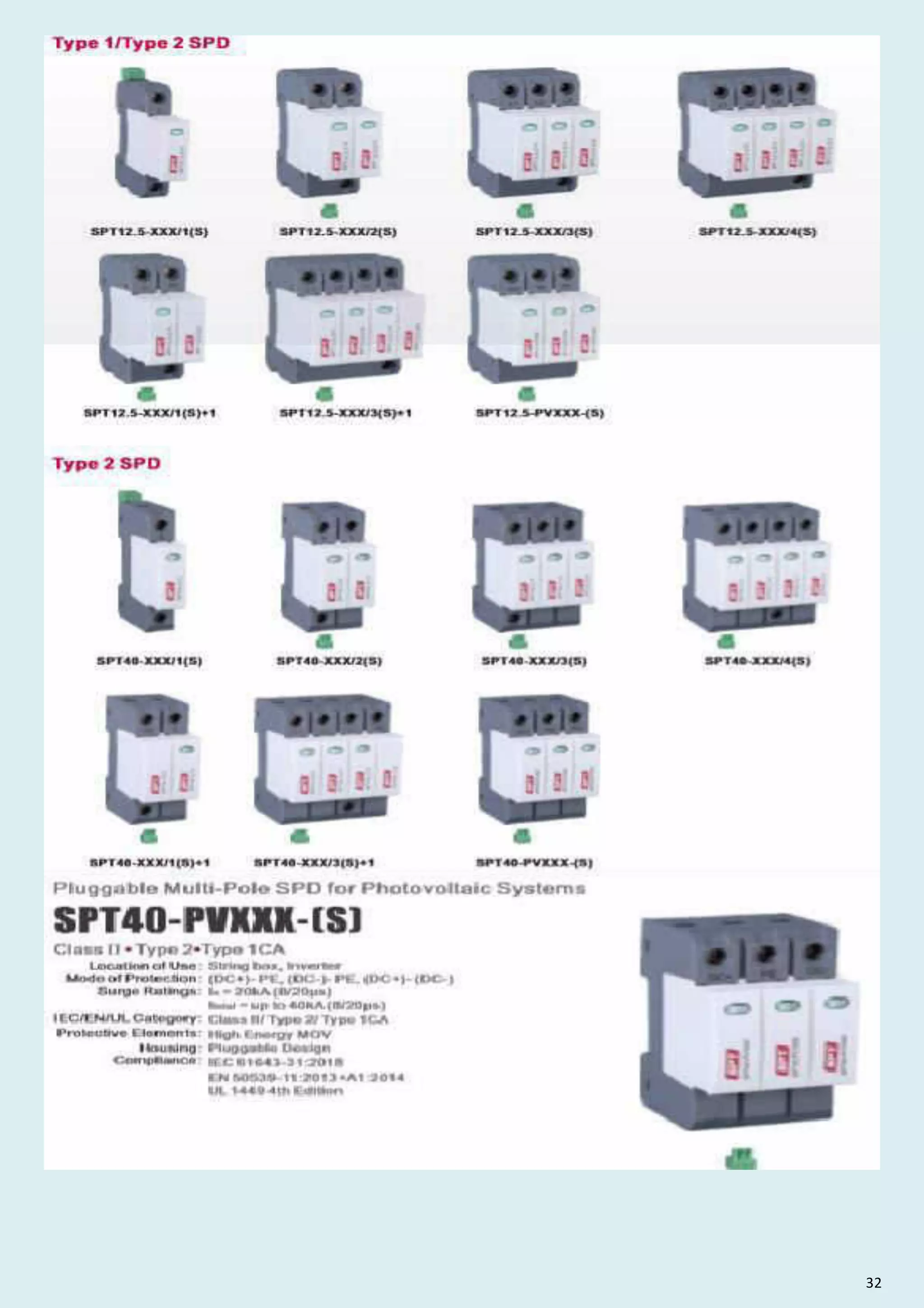
Pluggable Multi-Pole SPD for Photovoltaic Systems
SPT12.5-PVXXX-(S)
Location of Use:
Mode of Protection:
Surge Ratings:
IEC/EN/UL Category:
Protective Elements:
Housing:
Compliance:
String box, Inverter
(DC+)- PE, (DC-)- PE, (DC+)- (DC-)
Itotal = up to 12.5 kA (10/350 µs)
Itotal = up to 40 kA (8/20 µs)
Class I+II / Type 1+2 / Type 1CA
High Energy MOV
Pluggable Design
IEC 61643-31:2018
EN 50539-11:2013+A1:2014
UL 1449 4th Edition](https://image.slidesharecdn.com/buildingautomationnetworkingcommunicationpresentationbylvs2022-220423035623/75/Building-Automation-Networking-Communication-Presentation-by-LVS-2022-pdf-169-2048.jpg)
![Order Information
Order Code
SPT12.5- PVXXX
SPT12.5- PVXXX-(S) (with remote contacts)
SPT12.5- PVXXX/0 (spare modules)
600 1000 1200 1500
0760025
0760026
0760002
0710235
0710236
0710202
0712231
0712232
0712202
0715231
0715232
0715202
Dimensions Packaging
RoHS
28
www.surgeprotec.com
Internal Configuration
Dimensions Packaging
PE Protective Earth
S Signalling Contacts Optional
Dimensions Packaging
600 1000 1200
Single Unit DIN 43880 Dimension 1 CTN
Packaging Dimensions (H x W x L)
Minimum Order Quantity 32 Units
[220 × 230 × 330 mm]
1500
Dimensions Packaging
SPT12.5-PVXXX/0 600 1000 1200
Single Unit DIN 43880 Dimension 1 CTN
Packaging Dimensions (H x W x L)
Minimum Order Quantity 64 Units
[220 × 230 × 330 mm]
1500
16 Units 16 Units 16 Units
SPT12.5-PVXXX-(S)
SPT12.5-PVXXX-(S)
Legend
Plug Internal Configuration](https://image.slidesharecdn.com/buildingautomationnetworkingcommunicationpresentationbylvs2022-220423035623/75/Building-Automation-Networking-Communication-Presentation-by-LVS-2022-pdf-170-2048.jpg)
![Location of Use: Sub-Distribution Boards
Network Systems: TN-S, TN-C, TT (only L-N)
Mode of Protection: L-PE, N-PE (only TN-S), L-PEN, L-N
Surge Ratings: In = 20 kA(8/20 µs)
IEC/EN/UL Category: Class II / Type 2 / Type 1CA
Protective Elements: High Energy MOV
Housing: Pluggable Design
Compliance: IEC 61643-11:2011
EN 61643-11:2012
UL 1449 4th Edition
SURGE PROTEC
Surge Protection Total Solutions
Class II Type 2 Type 1CA
• •
29 www.surgeprotec.com
Technical Data
SPT40-XXX/1(S) 75 150 275 320 385 440
Pluggable Single-Pole SPD
SPT40-XXX/1(S)
Mechanical Environmental
-40 ºF to +158 ºF [-40 ºC to +70 ºC]
5%...95%
80k Pa ... 106k Pa / -500 m ... 2000 m
Ta
RH
Mmax 39.9 Ibf·in [4.5 Nm]
2 AWG (Solid, Stranded) / 4 AWG (Flexible)
35 mm2 (Solid, Stranded) / 25 mm2 (Flexible)
35 mm DIN Rail, EN 60715
IP 20 (built-in)
Thermoplastic: Extinguishing Degree UL 94 V-0
Green ok / Red defect
Optional
AC: 250V / 0.5 A; DC: 250V / 0.1 A; 125 V / 0.2 A; 75 V / 0.5 A
Operating Temperature Range
Permissible Operating Humidity
Atmospheric pressure and altitude
Terminal Screw Torque
Conductor Cross Section (max)
Mounting
Degree of Protection
Housing Material
Thermal Protection
Operating State / Fault Indication
Remote Contacts (RC)
RC Switching Capacity
RC Conductor Cross Section (max) 16 AWG (Solid) / 1.5 mm2(Solid)
Yes
UL Electrical
MCOV 320 V 385 V 440 V
VPR 600 V 900 V 1000 V 1200 V 1500 V
In 20 kA 20 kA 20 kA 20 kA 20 kA
Maximum Continuous Operating Voltage (AC)
Voltage Protection Rating
Nominal Discharge Current (8/20 µs)
Short-Circuit Current Rating (AC) SCCR 150 kA
150 V
75 V
330 V
20 kA
150 kA 150 kA 200 kA
200 kA
100 kA
275 V
IEC Electrical
Nominal AC Voltage (50/60Hz) Uo/ Un 230 V 400 V
Maximum Continuous Operating Voltage (AC) Uc 320 V 385 V 440 V
Nominal Discharge Current (8/20 µs) In 20 kA 20 kA 20 kA 20 kA 20 kA
Maximum Discharge Current (8/20 µs) Imax 40 kA 40 kA 40 kA 40 kA 40 kA
230 V
230 V
275 V
20 kA
40 kA
120 V
150 V
60 V
75 V
Voltage Protection Level Up 1000 V 1500 V 1600 V 1750 V 2000 V
Response Time tA 25 ns
Back-Up Fuse (max)
Short-Circuit Current Rating (AC) ISCCR 25 kA / 50 kA
TOV Withstand 5s
UT 90 V 180 V 335 V 580 V
TOV 120min
UT 115 V 230 V 440 V
mode Withstand Safe Fail Safe Fail Safe Fail Safe Fail
Number of Ports 1
765 V
335 V
440 V
335 V
440 V
400 V
125 A gL / gG
Withstand](https://image.slidesharecdn.com/buildingautomationnetworkingcommunicationpresentationbylvs2022-220423035623/75/Building-Automation-Networking-Communication-Presentation-by-LVS-2022-pdf-171-2048.jpg)
![30
www.surgeprotec.com
Dimensions Packaging Dimensions Packaging
SPT40-XXX/1(S) 75 150 275 320 385 440
Single Unit DIN 43880 Dimension 1 CTN
Packaging Dimensions (H x W x L) [270 × 230 × 330 mm]
Minimum Order Quantity 72 Units
Internal Configuration
Dimensions Packaging Dimensions Packaging
SPT40-XXX/0 75 150 275 320 385 440
Single Unit DIN 43880 Dimension 1 CTN
Packaging Dimensions (H x W x L)
Minimum Order Quantity 96 Units
Legend
[270 × 230 × 330 mm]
Connection Diagram
TN-S, TN-C, TT (Single-phase, 1+0)
RoHS
Order Information
Order Code 75 150 275 320 385 440
SPT40-XXX/1 4007511
(with remote contacts)
SPT40-XXX/1S
4015011 4027511 4032011 4038511 4044011
4007512 4015012 4027512 4032012 4038512 4044012
SPT40-XXX/0 4007501 4015001 4027501 4032001 4038501 4044001
( )
spare modules
SPT40-XXX/1(S)
L Line
N Neutral
PE Protective Earth
S Signalling Contacts Optional](https://image.slidesharecdn.com/buildingautomationnetworkingcommunicationpresentationbylvs2022-220423035623/75/Building-Automation-Networking-Communication-Presentation-by-LVS-2022-pdf-172-2048.jpg)
![Location of Use: Sub-Distribution Boards
Network Systems: TN-S
Mode of Protection: L-PE, N-PE
Surge Ratings: In = 20 kA(8/20 µs)
IEC/EN/UL Category: Class II / Type 2 / Type 1CA
Protective Elements: High Energy MOV
Housing: Pluggable Design
Compliance: IEC 61643-11:2011
EN 61643-11:2012
UL 1449 4th Edition
Technical Data
SPT40-XXX/2(S) 75 150 275 320 385 440
IEC Electrical
Nominal AC Voltage (50/60Hz) Uo/ Un 230 V 400 V
Uc 320 V 385 V 440 V
Nominal Discharge Current (8/20 µs) In 20 kA 20 kA 20 kA 20 kA 20 kA
Maximum Discharge Current (8/20 µs) Imax 40 kA 40 kA 40 kA 40 kA 40 kA
230 V
230 V
275 V
20 kA
40 kA
120 V
150 V
60 V
75 V
Voltage Protection Level Up 1000 V 1500 V 1600 V 1750 V 2000 V
Response Time tA 25 ns
Back-Up Fuse (max)
Short-Circuit Current Rating (AC) ISCCR 25 kA / 50 kA
TOV Withstand 5s UT 90 V 180 V 335 V 580 V
TOV 120min UT 115 V 230 V 440 V
mode Withstand Safe Fail Safe Fail Safe Fail Safe Fail
Number of Ports 1
UL Electrical
Maximum Continuous Operating Voltage (AC) MCOV 320 V 385 V 440 V
Voltage Protection Rating VPR 600 V 900 V 1000 V 1200 V 1500 V
Nominal Discharge Current(8/20 µs) In 20 kA 20 kA 20 kA 20 kA 20 kA
Short-Circuit Current Rating (AC) SCCR 150 kA
Mechanical Environmental
Ta -40 ºF to +158 ºF [-40 ºC to +70 ºC]
RH 5%...95%
80k Pa ... 106k Pa / -500 m ... 2000 m
Mmax 39.9 Ibf·in [4.5 Nm]
2 AWG (Solid, Stranded) / 4 AWG (Flexible)
35 mm2 (Solid, Stranded) / 25 mm2 (Flexible)
35 mm DIN Rail, EN 60715
IP 20 (built-in)
Thermoplastic: Extinguishing Degree UL 94 V-0
Green ok / Red defect
Optional
AC: 250V / 0.5 A;DC: 250V / 0.1 A; 125 V / 0.2 A; 75 V / 0.5 A
Operating Temperature Range
Permissible Operating Humidity
Atmospheric pressure and altitude
Terminal Screw Torque
Conductor Cross Section (max)
Mounting
Degree of Protection
Housing Material
Thermal Protection
Operating State / Fault Indication
Remote Contacts (RC)
RC Switching Capacity
RC Conductor Cross Section (max) 16 AWG (Solid) / 1.5 mm (Solid)
Yes
765 V
335 V
440 V
335 V
440 V
150 V
75 V
330 V
400 V
20 kA
150 kA 150 kA 200 kA
200 kA
100 kA
275 V
125 A gL / gG
Withstand
SPT40-XXX/2(S)
Pluggable Multi-Pole SPD
SURGE PROTEC
Surge Protection Total Solutions
31 www.surgeprotec.com
Class II Type 2 Type 1CA
• •
2
Maximum Continuous Operating Voltage (AC)](https://image.slidesharecdn.com/buildingautomationnetworkingcommunicationpresentationbylvs2022-220423035623/75/Building-Automation-Networking-Communication-Presentation-by-LVS-2022-pdf-173-2048.jpg)
![32
www.surgeprotec.com
SPT40-XXX/2(S)
Dimensions Packaging
Dimensions Packaging
Legend
L
N
Protective Earth
S Signalling Contacts Optional
Line
Neutral
PE
Connection Diagram
TN-S (Single-phase, 2+0)
RoHS
Internal Configuration
Order Information
Order Code 75 150 275 320 385 440
SPT40-XXX/2 4007521
(with remote contacts)
SPT40-XXX/2S
4015021 4027521 4032021 4038521 4044021
4007522 4015022 4027522 4032022 4038522 4044022
SPT40-XXX/0 4007501 4015001 4027501 4032001 4038501 4044001
( )
spare modules
Dimensions Packaging
SPT40-XXX/2(S) 75 150 275 320 385 440
Single Unit DIN 43880 Dimension 1 CTN
Packaging Dimensions (H x W x L) [270 × 230 × 330 mm]
Minimum Order Quantity 42 Units
Dimensions Packaging
SPT40-XXX/0 75 150 275 320 385 440
Single Unit DIN 43880 Dimension 1 CTN
Packaging Dimensions (H x W x L)
Minimum Order Quantity 96 Units
[270 × 230 × 330 mm]](https://image.slidesharecdn.com/buildingautomationnetworkingcommunicationpresentationbylvs2022-220423035623/75/Building-Automation-Networking-Communication-Presentation-by-LVS-2022-pdf-174-2048.jpg)
![275 320 385 440
IEC Electrical
Nominal AC Voltage (50/60Hz) Uo/ Un 230 V 400 V
Maximum Continuous Operating Voltage (AC) Uc 320 V 385 V 440 V
Nominal Discharge Current (8/20 µs) In 20 kA 20 kA 20 kA 20 kA 20 kA
Maximum Discharge Current (8/20 µs) Imax 40 kA 40 kA 40 kA 40 kA 40 kA
230 V
230 V
275 V
120 V
150 V
Voltage Protection Level Up 1000 V 1500 V 1600 V 1750 V 2000 V
Response Time tA 25 ns
Back-Up Fuse (max)
Short-Circuit Current Rating (AC) ISCCR 25 kA / 50 kA
TOV Withstand 5s UT 180 V 335 V 580 V
TOV 120min UT 230 V 440 V
mode Safe Fail Safe Fail Safe Fail Safe Fail
Number of Ports 1
UL Electrical
MCOV 320 V 385 V 440 V
VPR 600 V 900 V 1000 V 1200 V 1500 V
In 20 kA 20 kA 20 kA 20 kA 20 kA
Maximum Continuous Operating Voltage (AC)
Voltage Protection Rating
Nominal Discharge Current (8/20 µs)
Short-Circuit Current Rating (AC) SCCR 150 kA
Mechanical Environmental
Ta -40 ºF to +158 ºF [-40 ºC to +70 ºC]
RH 5%...95%
80k Pa ... 106k Pa / -500 m ... 2000 m
Mmax 39.9 Ibf·in [4.5 Nm]
2 AWG (Solid, Stranded) / 4 AWG (Flexible)
35 mm2 (Solid, Stranded) / 25 mm2 (Flexible)
35 mm DIN Rail, EN 60715
IP 20 (built-in)
Thermoplastic: Extinguishing Degree UL 94 V-0
Green ok / Red defect
Optional
AC: 250V / 0.5 A; DC: 250V / 0.1 A; 125 V / 0.2 A; 75 V / 0.5 A
Operating Temperature Range
Permissible Operating Humidity
Atmospheric pressure and altitude
Terminal Screw Torque
Conductor Cross Section (max)
Mounting
Degree of Protection
Housing Material
Thermal Protection
Operating State / Fault Indication
Remote Contacts (RC)
RC Switching Capacity
RC Conductor Cross Section (max) 16 AWG (Solid) / 1.5 mm (Solid)
Yes
765 V
335 V
440 V
335 V
440 V
150 V
150 kA 150 kA 200 kA
200 kA
275 V
125 A gL / gG
Withstand
150
Technical Data
SPT40-XXX/3(S)
Location of Use: Sub-Distribution Boards
Network Systems: TN-C
Mode of Protection: L-PEN
Surge Ratings: In = 20 kA(8/20 µs)
IEC/EN/UL Category: Class II / Type 2 / Type 1CA
Protective Elements: High Energy MOV
Housing: Pluggable Design
Compliance: IEC 61643-11:2011
EN 61643-11:2012
UL 1449 4th Edition
SURGE PROTEC
Surge Protection Total Solutions
33 www.surgeprotec.com
Class II Type 2 Type 1CA
• •
Pluggable Multi-Pole SPD
SPT40-XXX/3(S)
2](https://image.slidesharecdn.com/buildingautomationnetworkingcommunicationpresentationbylvs2022-220423035623/75/Building-Automation-Networking-Communication-Presentation-by-LVS-2022-pdf-175-2048.jpg)
![34
www.surgeprotec.com
SPT40-XXX/3(S)
Order Information
Order Code 150 275 320 385 440
SPT40-XXX/3
(with remote contacts)
SPT40-XXX/3S
4015031 4027531 4032031 4038531 4044031
4015032 4027532 4032032 4038532 4044032
SPT40-XXX/0 4015001 4027501 4032001 4038501 4044001
( )
spare modules
Dimensions Packaging
Internal Configuration
Dimensions Packaging
Legend
L
N
Protective Earth
S Signalling Contacts Optional
Line
Neutral
PE
TN-C (Three-phase, 3+0)
Connection Diagram
RoHS
Dimensions Packaging
SPT40-XXX/0 150 275 320 385 440
Single Unit DIN 43880 Dimension 1 CTN
Packaging Dimensions (H x W x L)
Minimum Order Quantity 96 Units
[270 × 230 × 330 mm]
Dimensions Packaging
SPT40-XXX/3(S) 150 275 320 385 440
Single Unit DIN 43880 Dimension 1 CTN
Packaging Dimensions (H x W x L) [270 × 230 × 330 mm]
Minimum Order Quantity 30 Units](https://image.slidesharecdn.com/buildingautomationnetworkingcommunicationpresentationbylvs2022-220423035623/75/Building-Automation-Networking-Communication-Presentation-by-LVS-2022-pdf-176-2048.jpg)
![Pluggable Multi-Pole SPD
SPT40-XXX/4(S)
Technical Data
SPT40-XXX/4(S) 275 320 385 440
IEC Electrical
Uo/ Un 230 V 400 V
Uc 320 V 385 V 440 V
In 20 kA 20 kA 20 kA 20 kA 20 kA
Imax 40 kA 40 kA 40 kA 40 kA 40 kA
230 V
230 V
275 V
120 V
150 V
Up 1000 V 1500 V 1600 V 1750 V 2000 V
tA 25 ns
ISCCR 25 kA / 50 kA
UT 180 V 335 V 580 V
UT 230 V 440 V
mode Safe Fail Safe Fail Safe Fail Safe Fail
Nominal AC Voltage (50/60Hz)
Maximum Continuous Operating Voltage (AC)
Nominal Discharge Current (8/20 µs)
Maximum Discharge Current (8/20 µs)
Voltage Protection Level
Response Time
Back-Up Fuse (max)
Short-Circuit Current Rating (AC)
TOV Withstand 5s
TOV 120min
Number of Ports 1
UL Electrical
MCOV 320 V 385 V 440 V
VPR 600 V 900 V 1000 V 1200 V 1500 V
In 20 kA 20 kA 20 kA 20 kA 20 kA
Maximum Continuous Operating Voltage (AC)
Voltage Protection Rating
Nominal Discharge Current (8/20 µs)
Short-Circuit Current Rating (AC) SCCR 150 kA
Mechanical Environmental
Ta -40 ºF to +158 ºF [-40 ºC to +70 ºC]
RH 5%...95%
80k Pa ... 106k Pa / -500 m ... 2000 m
Mmax 39.9 Ibf·in [4.5 Nm]
2 AWG (Solid, Stranded) / 4 AWG (Flexible)
35 mm2 (Solid, Stranded) / 25 mm2 (Flexible)
35 mm DIN Rail, EN 60715
IP 20 (built-in)
Thermoplastic: Extinguishing Degree UL 94 V-0
Green ok / Red defect
Optional
AC: 250V / 0.5 A;DC: 250V / 0.1 A; 125 V / 0.2 A; 75 V / 0.5 A
Operating Temperature Range
Permissible Operating Humidity
Atmospheric pressure and altitude
Terminal Screw Torque
Conductor Cross Section (max)
Mounting
Degree of Protection
Housing Material
Thermal Protection
Operating State / Fault Indication
Remote Contacts (RC)
RC Switching Capacity
RC Conductor Cross Section 16 AWG (Solid) / 1.5 mm2(Solid)
Yes
765 V
335 V
440 V
335 V
440 V
150 V
150 kA 150 kA 200 kA
200 kA
275 V
125 A gL / gG
Withstand
150
SURGE PROTEC
Surge Protection Total Solutions
35 www.surgeprotec.com
Class II Type 2 Type 1CA
• •
Location of Use: Sub-Distribution Boards
Network Systems: TN-S
Mode of Protection: L-PE, N-PE
Surge Ratings: In = 20 kA(8/20 µs)
IEC/EN/UL Category: Class II / Type 2 / Type 1CA
Protective Elements: High Energy MOV
Housing: Pluggable Design
Compliance: IEC 61643-11:2011
EN 61643-11:2012
UL 1449 4th Edition](https://image.slidesharecdn.com/buildingautomationnetworkingcommunicationpresentationbylvs2022-220423035623/75/Building-Automation-Networking-Communication-Presentation-by-LVS-2022-pdf-177-2048.jpg)
![Dimensions Packaging
Dimensions Packaging
SPT40-XXX/4(S) 150 275 320 385 440
Single Unit DIN 43880 Dimension 1 CTN
Packaging Dimensions (H x W x L) [270 × 230 × 330 mm]
Minimum Order Quantity 24 Units
Dimensions Packaging Dimensions Packaging
SPT40-XXX/0 150 275 320 385 440
Single Unit DIN 43880 Dimension 1 CTN
Packaging Dimensions (H x W x L)
Minimum Order Quantity 96 Units
[270 × 230 × 330 mm]
Connection Diagram
TN-S (Three-phase, 4+0)
RoHS
36
www.surgeprotec.com
SPT40-XXX/4(S)
Order Information
Order Code 150 275 320 385 440
SPT40-XXX/4
(with remote contacts)
SPT40-XXX/4S
4015041 4027541 4032041 4038541 4044041
4015042 4027542 4032042 4038542 4044042
SPT40-XXX/0 4015001 4027501 4032001 4038501 4044001
( )
spare modules
Legend
L
N
Protective Earth
S Signalling Contacts Optional
Line
Neutral
PE
Internal Configuration](https://image.slidesharecdn.com/buildingautomationnetworkingcommunicationpresentationbylvs2022-220423035623/75/Building-Automation-Networking-Communication-Presentation-by-LVS-2022-pdf-178-2048.jpg)
![Pluggable Multi-Pole SPD
SPT40-XXX/1(S)+1
Technical Data
75 150 275 320
(L - N) Uc
(N - PE) Uc 255 V 255 V 255 V 255 V
(L - N) / (N - PE) In 20 kA / 20 kA
(L - N) / (N - PE) Imax 40 kA / 40 kA
SPT40-XXX/1(S)+1
IEC Electrical
230 V
230 V
120 V
60 V
320 V
275 V
150 V
75 V
(L - N) / (N - PE) Up 400 V/ 1000 V 1000 V/ 1000 V 1500 V/ 1000 V 1600 V/ 1000 V
(N-PE) Ifi 100 A RMS
(L - N) / (N - PE) tA 25 ns / 100 ns
(L - N) ISCCR 25 kA / 50 kA
(L - N) UT
(L - N) UT
mode Withstand Safe Fail Safe Fail
(N - PE) UT 1200 V
Nominal AC Voltage (50/60Hz)
Maximum Continuous Operating Voltage
Nominal Discharge Current (8/20 µs)
Maximum Discharge Current (8/20 µs)
Voltage Protection Level
Follow Current Interrupt Rating
Response Time
Back-Up Fuse (max)
Short-Circuit Current Rating (AC)
TOV Withstand 5s
TOV 120min
TOV Withstand 200ms
Number of Ports 1
UL Electrical
(L - N) / (N - PE) MCOV 275 V / 255 V
(L - N) / (N - PE) VPR 600 V / 1000 V
(L - N) / (N - PE) In 20 kA / 20 kA 20 kA / 20 kA
Maximum Continuous Operating Voltage (AC)
Voltage Protection Rating
Nominal Discharge Current (8/20 µs)
Short-Circuit Current Rating (AC) (L - N) SCCR
Mechanical Environmental
Ta -40 ºF to +158 ºF [-40 ºC to +70 ºC]
RH 5%...95%
Mmax [
39.9 Ibf·in 4.5 Nm]
2 AWG (Solid, Stranded) / 4 AWG (Flexible)
35 mm2 (Solid, Stranded) / 25 mm2(Flexible)
35 mm DIN Rail, EN 60715
IP 20 (built-in)
Thermoplastic: Extinguishing Degree UL 94 V-0
Optional
16 AWG (Solid) / 1.5 mm2(Solid)
90 V 180 V 335 V
115 V 230 V 440 V
335 V
440 V
150 kA
200 kA
100 kA
75 V / 255 V 150 V / 255 V
330 V / 1000 V
320 V / 255 V
20 kA / 20 kA
150 kA
1000 V / 1000 V
900 V / 1000 V
20 kA / 20 kA
Operating Temperature Range
Permissible Operating Humidity
Terminal Screw Torque
Conductor Cross Section (max)
Mounting
Degree of Protection
Housing Material
Thermal Protection
Operating State / Fault Indication
Remote Contacts (RC)
RC Switching Capacity
RC Conductor Cross Section (max)
Atmospheric pressure and altitude 80k Pa ... 106k Pa / -500 m ... 2000 m
Yes
Green ok / Red defect
AC: 250V / 0.5 A; DC: 250V / 0.1 A; 125 V / 0.2 A; 75 V / 0.5 A
125 A gL / gG
Withstand
Location of Use:
Network Systems: TT, TN-S
Mode of Protection: L-N, N-PE
Sub-Distribution Boards
Surge Ratings: In = 20 kA(8/20µs)
IEC/EN/UL Category: Class II / Type 2 / Type 1CA
Protective Elements: High Energy MOV and GDT
Housing: Pluggable Design
Compliance: IEC 61643-11:2011
EN 61643-11:2012
UL 1449 4th Edition
SURGE PROTEC
Surge Protection Total Solutions
Class II Type 2 Type 1CA
• •
37 www.surgeprotec.com](https://image.slidesharecdn.com/buildingautomationnetworkingcommunicationpresentationbylvs2022-220423035623/75/Building-Automation-Networking-Communication-Presentation-by-LVS-2022-pdf-179-2048.jpg)
![Order Information
Order Code 75 150 275 320
SPT40-XXX/1+1
(with remote contacts)
SPT40-XXX/1S+1
SPT40-XXX/0
SPT40-NPE/0
4007513
4007514
4007501
4025501
4015013
4015014
4015001
4025501
4027513
4027514
4027501
4025501
4032013
4032014
4032001
4025501
( )
spare modules
( )
spare modules
Dimensions Packaging
Internal Configuration
Legend
L
N
Protective Earth
S Signalling Contacts Optional
Line
Neutral
PE
SPT40-XXX/1(S)+1
Dimensions Packaging
SPT40-XXX/1(S)+1 75 150 275 320
Single Unit DIN 43880 Dimension 1 CTN
Packaging Dimensions (H x W x L)
Minimum Order Quantity 42 Units
[270 × 230 × 330 mm]
Dimensions Packaging
Connection Diagram
TN-S,TT (Single-phase, 1+1)
RoHS
Dimensions Packaging
SPT40-XXX/0 150 275 320
75
Single Unit DIN 43880 Dimension 1 CTN
Packaging Dimensions (H x W x L)
Minimum Order Quantity 96 Units
SPT40-NPE/0 40
[270 × 230 × 330 mm]
38
www.surgeprotec.com](https://image.slidesharecdn.com/buildingautomationnetworkingcommunicationpresentationbylvs2022-220423035623/75/Building-Automation-Networking-Communication-Presentation-by-LVS-2022-pdf-180-2048.jpg)
![275
Uc
Uc 255 V 255 V 255 V
In 20 kA / 20 kA
Imax 40 kA / 40 kA
IEC Electrical
230 V
230 V
120 V
320 V
275 V
150 V
Up 1000 V/ 1000 V 1500 V/ 1000 V 1600 V/ 1000 V
Ifi 100 A RMS
tA 25 ns / 100 ns
ISCCR 25 kA / 50 kA
UT
UT
Mode Safe Fail Safe Fail
UT 1200 V
Nominal AC Voltage (50/60Hz)
Maximum Continuous Operating Voltage
Nominal Discharge Current (8/20 µs)
Maximum Discharge Current (8/20 µs)
Voltage Protection Level
Follow Current Interrupt Rating
Response Time
Back-Up Fuse (max)
Short-Circuit Current Rating (AC)
TOV Withstand 5s
TOV 120min
TOV Withstand 200ms
Number of Ports 1
UL Electrical
MCOV 275 V / 255 V 320 V / 255 V
VPR 600 V / 1000 V
In 20 kA / 20 kA 20 kA / 20 kA 20 kA / 20 kA
Maximum Continuous Operating Voltage (AC)
Voltage Protection Rating
Nominal Discharge Current (8/20 µs)
Short-Circuit Current Rating (AC)
(L - N)
(N - PE)
(L - N) / (N - PE)
(L - N) / (N - PE)
(L - N) / (N - PE)
(N-PE)
(L - N) / (N - PE)
(L - N)
(L - N)
(L - N)
(N - PE)
(L - N) / (N - PE)
(L - N) / (N - PE)
(L - N) / (N - PE)
(L - N) SCCR
Mechanical Environmental
180 V 335 V
230 V 440 V
335 V
440 V
150 kA
150 kA
200 kA
150 V / 255 V
1000 V / 1000 V
900 V / 1000 V
320
150 385
125 A gL / gG
Withstand Safe Fail
335 V
440 V
230 V
385 V
255 V
1750 V/ 1000 V
320 V / 255 V
20 kA / 20 kA
150 kA
1200 V / 1000 V
SURGE PROTEC
Surge Protection Total Solutions
Technical Data
39 www.surgeprotec.com
SPT40-XXX/3(S)+1
SPT40-XXX/3(S)+1
Pluggable Multi-Pole SPD
Class II Type 2 Type 1CA
• •
Ta -40 ºF to +158 ºF [-40 ºC to +70 ºC]
RH 5%...95%
Mmax [
39.9 Ibf·in 4.5 Nm]
2 AWG (Solid, Stranded) / 4 AWG (Flexible)
35 mm2 (Solid, Stranded) / 25 mm2(Flexible)
35 mm DIN Rail, EN 60715
IP 20 (built-in)
Thermoplastic: Extinguishing Degree UL 94 V-0
Optional
16 AWG (Solid) / 1.5 mm2(Solid)
Operating Temperature Range
Permissible Operating Humidity
Terminal Screw Torque
Conductor Cross Section (max)
Mounting
Degree of Protection
Housing Material
Thermal Protection
Operating State / Fault Indication
Remote Contacts (RC)
RC Switching Capacity
RC Conductor Cross Section (max)
Atmospheric pressure and altitude 80k Pa ... 106k Pa / -500 m ... 2000 m
Yes
Green ok / Red defect
AC: 250V / 0.5 A;DC: 250V / 0.1 A; 125 V / 0.2 A; 75 V / 0.5 A
Location of Use:
Network Systems: TT, TN-S
Mode of Protection: L-N, N-PE
Sub-Distribution Boards
Surge Ratings: In = 20 kA(8/20 µs)
IEC/EN/UL Category: Class II / Type 2 / Type 1CA
Protective Elements: High Energy MOV and GDT
Housing: Pluggable Design
Compliance: IEC 61643-11:2011
EN 61643-11:2012
UL 1449 4th Edition](https://image.slidesharecdn.com/buildingautomationnetworkingcommunicationpresentationbylvs2022-220423035623/75/Building-Automation-Networking-Communication-Presentation-by-LVS-2022-pdf-181-2048.jpg)
![40
www.surgeprotec.com
Order Information
Order Code 150 275 320
SPT40-XXX/3+1
(with remote contacts)
SPT40-XXX/3S+1
SPT40-XXX/0
SPT40-NPE/0
4015033
4015034
4015001
4025501
4027533
4027534
4027501
4025501
4032033
4032034
4032001
4025501
385
4038533
4038534
4038501
4025501
( )
spare modules
( )
spare modules
SPT40-XXX/3(S)+1
Dimensions Packaging
Dimensions Packaging
Internal Configuration
Legend
L
N
Protective Earth
S Signalling Contacts Optional
Line
Neutral
PE
Connection Diagram
Dimensions Packaging
SPT40-XXX/0 150 275 320
Single Unit DIN 43880 Dimension 1 CTN
Packaging Dimensions (H x W x L)
Minimum Order Quantity 96 Units
SPT40-NPE/0 40
[270 × 230 × 330 mm]
385
TN-S, TT (Three-phase, 3+1)
RoHS
Dimensions Packaging
SPT40-XXX/3(S)+1 150 275 320
Single Unit DIN 43880 Dimension 1 CTN
Packaging Dimensions (H x W x L)
Minimum Order Quantity 24 Units
[270 × 230 × 330 mm]
385](https://image.slidesharecdn.com/buildingautomationnetworkingcommunicationpresentationbylvs2022-220423035623/75/Building-Automation-Networking-Communication-Presentation-by-LVS-2022-pdf-182-2048.jpg)
![SURGE PROTEC
Surge Protection Total Solutions
41 www.surgeprotec.com
Pluggable Multi-Pole SPD for Photovoltaic Systems
SPT40-PVXXX-(S)
Class II Type 2 Type 1CA
• •
Mechanical Environmental
Technical Data
SPT40-PVXXX-(S) 600 1000 1200 1500
IEC Electrical
20 kA
600 V
600 V
1000 V
1000 V
1200 V
1200 V
1500 V
1500 V
40 kA
40 kA
2200 V
2200 V
4000 V
4000 V
4400 V
4400 V
5200 V
5200 V
2000A
1
Maximum Continuous Operating DC Voltage (DC+) - PE, (DC-) - PE
(DC+) - (DC-)
Nominal Discharge Current (8/20 µs)
Total Discharge Current (8/20 µs)
Maximum Discharge Current (8/20 µs)
Voltage Protection Level
Response Time
Short-Circuit Current Rating
Number of Ports
Ucpv
In
ITotal
Imax
Up
tA
Iscpv
Ucpv
Up
(DC+) - PE, (DC-) - PE
(DC+) - (DC-)
25 ns
Maximum Permitted DC Voltage
Voltage Protection Rating
Nominal Discharge Current (8/20 μs)
Short-Circuit Current Rating
(DC+) - PE, (DC-) - PE
(DC+) - (DC-)
Vpvdc
VPR
VPR
In
SCCR
600 V 1000 V 1200 V 1500 V
1600 V
1600 V
2500 V
2500 V
3000 V
3000 V
4000 V
4000 V
20 kA
35 kA 50 kA 55 kA 65 kA
UL Electrical
Ta -40 ºF to +158 ºF [-40 ºC to +70 ºC]
RH 5%...95%
Mmax [
39.9 Ibf·in 4.5 Nm]
2 AWG (Solid, Stranded) / 4 AWG (Flexible)
35 mm2 (Solid, Stranded) / 25 mm2(Flexible)
35 mm DIN Rail, EN 60715
IP 20 (built-in)
Thermoplastic: Extinguishing Degree UL 94 V-0
Optional
16 AWG (Solid) / 1.5 mm2(Solid)
Operating Temperature Range
Permissible Operating Humidity
Terminal Screw Torque
Conductor Cross Section (max)
Mounting
Degree of Protection
Housing Material
Thermal Protection
Operating State / Fault Indication
Remote Contacts (RC)
RC Switching Capacity
RC Conductor Cross Section (max)
Atmospheric pressure and altitude 80k Pa ... 106k Pa / -500 m ... 2000 m
Yes
Green ok / Red defect
AC: 250V / 0.5 A; DC: 250V / 0.1 A; 125 V / 0.2 A; 75 V / 0.5 A
Location of Use:
Mode of Protection:
Surge Ratings:
IEC/EN/UL Category:
Protective Elements:
Housing:
Compliance:
String box, Inverter
(DC+)- PE, (DC-)- PE, (DC+)- (DC-)
In = 20kA (8/20μs)
Itotal = up to 40kA (8/20μs)
Class II/ Type 2/ Type 1CA
High Energy MOV
Pluggable Design
IEC 61643-31:2018
EN 50539-11:2013+A1:2014
UL 1449 4th Edition](https://image.slidesharecdn.com/buildingautomationnetworkingcommunicationpresentationbylvs2022-220423035623/75/Building-Automation-Networking-Communication-Presentation-by-LVS-2022-pdf-183-2048.jpg)
![Dimensions Packaging
RoHS
SPT40-PVXXX-(S)
42
www.surgeprotec.com
Internal Configuration
Dimensions Packaging
SPT40-PV1500-(S)
SPT40-PV1200-(S)
SPT40-PV1000-(S)
SPT40-PV600-(S)
Dimensions Packaging
600 1000 1200
Single Unit DIN 43880 Dimension 1 CTN
Packaging Dimensions (H x W x L)
Minimum Order Quantity 42 Units
[270 × 230 × 330 mm]
1500
Dimensions Packaging
SPT40-PVXXX/0 600 1000 1200
Single Unit DIN 43880 Dimension 1 CTN
Packaging Dimensions (H x W x L)
Minimum Order Quantity 96 Units
[270 × 230 × 330 mm]
1500
30 Units 30 Units 30 Units
SPT40-PVXXX-(S)
Order Information
Order Code 600 1000 1200 1500
SPT40-PVXXX
SPT40-PVXXX-(S) (with remote contacts)
SPT40-PVXXX/0 (spare modules )
4060025
4060026
4060002
4010235
4010236
4010202
4012231
4012232
4012202
4015231
4015232
4015202
PE Protective Earth
S Signalling Contacts Optional
Legend
Plug Internal Configuration](https://image.slidesharecdn.com/buildingautomationnetworkingcommunicationpresentationbylvs2022-220423035623/75/Building-Automation-Networking-Communication-Presentation-by-LVS-2022-pdf-184-2048.jpg)
![In-line SPD for Coaxial RF Systems
C1 C2 C3
• •
The SPT CP BNC Series of coaxial surge protectors is intended to protect RF antenna systems and is suitable for frequencies from
DC to 2.6 GHz.
It is designed as an in-line unit allowing ease of installation. The careful design, low capacitance gas discharge arresters and high
quality BNC-type termination connectors, ensures a minimum of insertion loss throughout the frequency band.
Transfer power is 40 W to 300 W continuous, depending on the coaxial cable protector voltage.
The CP coaxial cable protector is designed in accordance with IEC61643-21: 2012 standards and regulations.
A grounding stud is provided which should be connected to the system ground or coaxial feed-through bulkhead, as directly as possible.
Maximum Continuous Operating Voltage
Maximum Peak Power
C2 Nominal Discharge Current (8/20 µs)
Maximum Discharge Current (8/20 µs)
Residual Voltage at (1 kV/µs)
Impedance
Insertion Loss
Return Loss
Insulation Resistance of Protection
Frequency Range
SPT CP BNC
Mechanical
IEC Electrical
Temperature Range
Connection
Degree of Protection IEC/EN 60529
Housing Material
Order Information
Order Code
SPT CP BNC-FF-xxx
SPT CP BNC-MF-xxx
800 850 800 851 800 852
70 180 280
-40 ºF to +176 ºF [-40 ºC to +80 ºC]
BNC Female/Female BNC Male/Female
IP 20 (built-in)
Metal
70 180 280
180V
125 W
10 kA
20 kA
700V
500
0. 4dB ,
20dB
10GQ
0-2.6 GHz
800 853 800 854 800 855
SURGE PROTEC
Surge Protection Total Solutions
Technical Data
Uc
In
Imax
Z
70V
40W
Pmax
Ures
IL
RL
Riso
fG
600V
280V
300W
900V
43 www.surgeprotec.com
SPT CP BNC
IEC/EN Category:
Protection:
Maximum Operating:
Voltage:
Maximum Peak Power:
Frequency Range:
Surge Discharge Ratings:
Impedance:
Insertion Loss:
Return Loss:
Termination:
Housing:
Compliance:
C1/C2/C3
Impedance Matched
70, 180, 280 V
40, 125, 300 W
DC – 2.6 GHz
I n : 10 kA, I max : 20 kA
50 Ω
0.4 dB
20 dB
BNC Type (F-F, M-F)
In-line Installation, Shielded Enclosure
IEC/EN 61643-21](https://image.slidesharecdn.com/buildingautomationnetworkingcommunicationpresentationbylvs2022-220423035623/75/Building-Automation-Networking-Communication-Presentation-by-LVS-2022-pdf-185-2048.jpg)
![44
www.surgeprotec.com
Dimensions Packaging
Dimensions Packaging
SPT CP BNC-FF-xxx SPT CP BNC-MF-xxx
70 180 280 70 180 280
Weight per Unit 3.74oz [106g] 4.02 oz [114 g]
Packaging Dimensions (Single Unit) 2.9 × 1.2 × 1.2 [73 × 30 × 30 mm]
Minimum Package Quantity 100 pieces
Internal Configuration
Legend
SPT CP BNC
RoHS
GDT Gas Discharge Tube
PE Ground
SPT CP BNC](https://image.slidesharecdn.com/buildingautomationnetworkingcommunicationpresentationbylvs2022-220423035623/75/Building-Automation-Networking-Communication-Presentation-by-LVS-2022-pdf-186-2048.jpg)
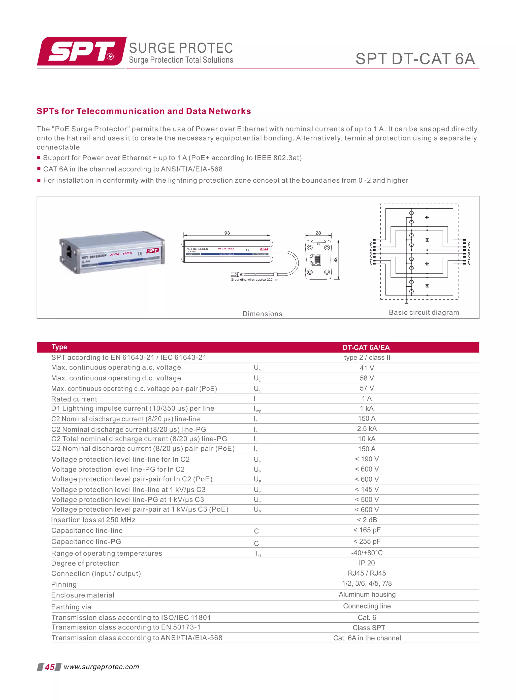
![Modular SPD for Single Pair
SPT-DC Series
D1 C1 C2 C3
• • •
5 12 15 24 30* 48 60 110
Electrical
Lines Protected 1
Nominal Operating Voltage (DC) Un 5V 12 V 15 V 24 V 30 V 48 V 60 V 110 V
Maximum Continuous Operating Voltage (DC) Uc 6V 15 V 18 V 28 V 33 V 52 V 64 V 170 V
Rated Load Current at 25ºC IL 1A
C2 Nominal Discharge Current (8/20 µs) In 10kA
Maximum Discharge Current (8/20 µs) Imax 20kA
D1 Impulse Current (10/350 µs) Iimp 2.5kA
Residual Voltage at 5 kA (8/20 µs) Ures 22V 42 V 48 V 70 V 80 V 140 V 160 V 450 V
Rated Spark Overvoltage (Line-Ground) 7-10V 16-21 V 21-25 V 31-37 V 36-44 V 57-69 V 68-84 V 184-264 V
(Line-Line) 7-10V 16-21 V 21-25 V 31-37 V 36-44 V 57-69 V 68-84 V 184-264 V
Response Time Overvoltage Protection tA 1 ns
Thermal Protection Ye s
SURGE PROTEC
Surge Protection Total Solutions
IEC/ENCategory: D1/C1/C2/C3
ModeofProtection: Longitudinal,Transverse
CoarseProtection:
Voltages: 5,12,15,24,30*,48,60,110VDC
FrequencyRange: 30MHz
SurgeDischargeRatings: In:10kA,Imax:20kA,Iimp:2.5kA
SeriesLoadCurrent: 1A
Enclosure: DIN438802/3TE,DINRailMount
Terminals: Strandedto4mm2
Housing: ModularDesign
Compliance: IEC/EN61643-21
UL497B4thEdition
3TerminalGDT
Cut-off Frequency fG 30MHz
Order Information
Order Code 5 12 15 24 30* 48 60 110
SPT-DC-xxx 9086.33 9086.34 9086.35 9086.36 9082.80 9086.37 9086.38 9086.39
SPT-DC-xxxM (module) 9086.40 9086.41 9086.42 9086.43 9082.81 9086.44 9086.45 9086.46
Mechanical
Temperature Range -40 ºF to +176 ºF [-40 ºC to +80 ºC]
Terminal Cross Section Multi-strand (max.) 2 2
12 AWG [4 mm , 2.5 mm QVersion]
Degree of Protection IEC/EN 60529 IP20 (built-in)
Mounting IEC/EN 60715 35 mm DIN Rail
Technical Data
SPT-DC Series
Basic circuit diagram
1 1
2 2
PE PE
IN OUT
G D
L
L
D D
Dimensions
13
90
65
48
45
1 2
IN
OUT
1 2
PE
PE
SPT-DC Series
46
www.surgeprotec.com](https://image.slidesharecdn.com/buildingautomationnetworkingcommunicationpresentationbylvs2022-220423035623/75/Building-Automation-Networking-Communication-Presentation-by-LVS-2022-pdf-188-2048.jpg)
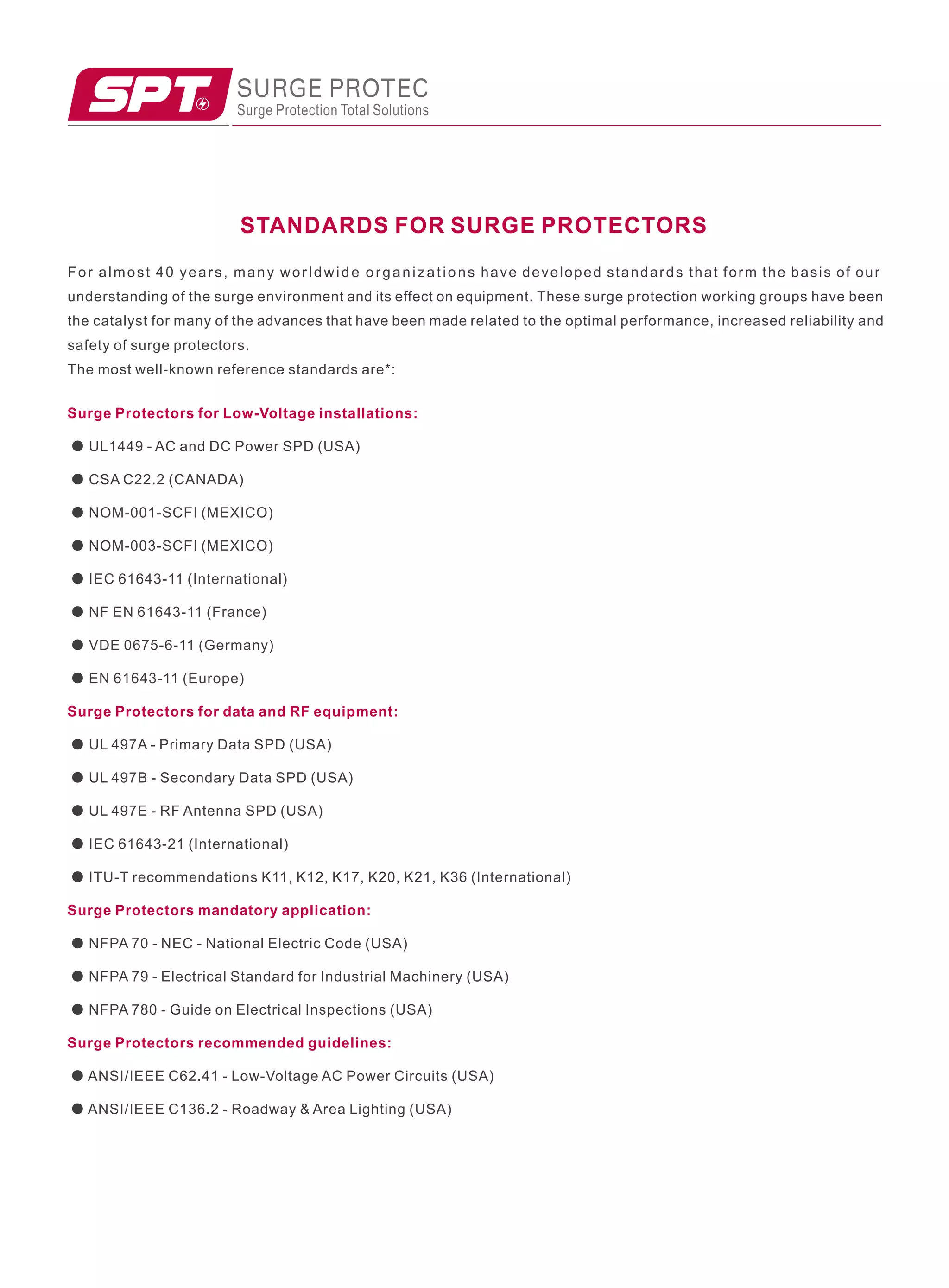

Link Vue System specializes in building automation, electrical consultancy, and security solutions for various sectors including solar power and electric vehicles. The company will be in Dubai/Sharja from February 7-13, 2022, to meet with consultants and EPC companies, offering a range of products and services including surge protection, earthing solutions, and smart data management systems. Additionally, they emphasize the importance of electrical safety and sustainability in modern infrastructure.


