Lightning it's not joke kills or destry only safety first

We are witness globally weather is changing due to development and destroy nature by Industries and Infrastructure Demand. Lightning strike to ground can not be stop but this can be control and discharge to ground safely using best and latest practice document for Installation of Lightning Protection available Follow IEC62305 Conventional and Advance Effective ESE Type Lightning Protection NFC17-102 . Now Days in India Many disaster happened more than 100 People Died due to Lightning and national Figure reported Human Loss 5000 or More and 1000 Cr. Value Assets burn partial of fully. Lightning Early Warning is Responsibility of Every Government along with mandatory of Installation Lightning Protection under Electrical Safety . Every Structure or Shed which is use for Public , other purpose Like Highways, Road ,Public Park , Museum should be protected from Lightning with Effective Earthing to discharge safely to ground. Earthing and Surge Protection is very important under Electrical Safety to protect assets and Human Life for any kind of threat due to Lightning and Other Surges Reason Over Voltage or Transients. Worldwide its duty of Engineering while design and Installation of any Projects for Building Infra, Industries and Public Transports Electrical Safety for any Power Supply to Equipment's will consider as priority and do Design ,Engineering ,Selection of Earthing ,Lightning and Surge Protection as per application and environment condition not a Similar BOQ for all Equipment's. They should also give proper instruction for installation and Maintenance procedure to ensure long life and Safety of Human and sustainability of Equipment Life with performance . Our Electrical and Fire Safety departments should aware latest National Electric Code follow and instruct all the Industries to follow same and ensure periodical maintenance by these people for safety of human Life and Valuable assets. All The Leading Insurance Companies who do Insurance under cover Fire and other Damage of Equipment's due to power should aware Electrical Safety Law and ask report from customer before accept any Insurance or issuing Policy otherwise they may have bear huge loss plz refer USA and other forward Company report loss due to Lightning and Electrical Short Circuit. Plz go through presentation Link Vue System Offering Design ,Engineering ,Selection of Genuine and Right Components , Supply and extending support for Installation . want to know more about us plz visit webpage www.linkvuesystem.com Call M- 9811247237 manav.chandra@linkvuesystem.com Mahesh Chandra Manav

Recommended
Recommended
More Related Content
What's hot
What's hot (20)
Similar to Lightning it's not joke kills or destry only safety first
Similar to Lightning it's not joke kills or destry only safety first (20)
More from Mahesh Chandra Manav
More from Mahesh Chandra Manav (20)
Recently uploaded
Recently uploaded (20)
Lightning it's not joke kills or destry only safety first
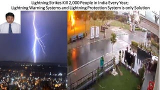
- 1. Lightning Strikes Kill 2,000People in India Every Year; Lightning Warning Systems and Lightning Protection System is only Solution
- 2. Advantages and disadvantages of the different Lightning Protection
- 3. 24X7Early Warning Lightning(We Alert to Safe yourAssets)
- 4. The useof an early lightning warning systemas both for thunderstorms formed over the area to be protected and for incoming thunderstorms (up to 40km), allows companies and public administrations to deploy temporary preventive actions capable of preventing or minimizing any possible damage. Systemprovides data which facilitates decision making, allowing an activity to be stopped only during the time of risk and restarting it once the risk is over. Lightning warning: The mostemployed technologies in lightning detection systems are: Based on an electrostatic field sensor. These are systems which monitor the environmental electrostatic field evolution which is produced by the electrical discharges presentin the stormclouds. This phenomenon can be detected from the first stage of the thunderstormformation so the alarm can anticipate the first discharge. Based on an electromagnetic field sensor. Thesesystems detect the electromagnetic impulses generated by electrical discharges and consequently they can only alert once the firstlightning bolt strikes. Aplicaciones Tecnológicas has developed and patented the Field-Controlled Electrometric Sensor to overcome the disadvantages of field mills, avoiding mobile parts. Lightning Early Warning Sensor System Electrostatic sensorItmonitors the conditions for the formation of thunderstorms over the target area (physicalextension where the alert is needed) with several tens of minutes of early warning. This information is directly related to lightning strike risk. This is a fully electronic system without mechanical mobile parts, which avoids any deterioration, obstruction or breakdown and therefore provides significant maintenance savings. Electromagnetic sensorItdetects active thunderstorms approaching the target area in a 40kmradius. Italso provides an estimation of the distance between the thunderstormand the target area. This information is complementary to the information about risk given by the electrostatic field sensor. Communication system The communication fromthe installed sensor is carried out through a private network (VPN), viaservers and reaching our control tools., Our systemensures redundancy with 2G/3G and LAN communication. Its operation is based on a global M2M systemwith particular channels to ensuredata delivery. This is a fully electronic system without mechanical mobile parts, which avoids any deterioration, obstruction or breakdown and therefore provides significant maintenance savings.,Electromagnetic sensorItdetects active thunderstorms approaching the target area in a 40kmradius. Italso provides an estimation of the distance between the thunderstormand the target area. This information is complementary to the information about risk given by the electrostatic field sensor. Communication system The communication fromthe installed sensor is carried out through a private network (VPN), viaservers and reaching via LAN communication. Its operation is based on a global M2M systemwith particular channels to ensuredata delivery. Acquisitionand processing system Servers in redundant locations. Remote monitoring fromAT. Privatebroadband communication Continuous improvement of the algorithms that process sensor readings, gradually increasing its adaptation to the local characteristics. Power stabilizers to ensurean immediate responsefromthe system. Sistemade alimentación ininterrumpida (SAI) queapoyatoda la infraestructura. Uninterruptible power supply (UPS) to supportthe entire infrastructure. Permanentsupervision of the readings fromthe detection units and the alert systemservices.
- 5. Alerts system Risk alerts arrive through different channels: private portal web, mobile phones, tablets, emails and the automation with remote relay modules, a multichannel management system so no alert goes unnoticed. Remote relay units can be connected to the alarms in a detection system. Each unit incorporates four potential-free or dry-contact outputs. The activation or deactivation is remotely controlled so all the process is 100% automated. The location of this device is independent of the detection unit since wiring is not necessary. This system allows total flexibility in different alarm systems: public addressing systems, panels, UPS units, sirens, strobe lights, etc. Areas of application of lightning warning systems,It is very useful for decision makers from the public and private sector to have information from these warning systems to protect individuals, goods and services against the adverse effects caused by thunderstorms. Besides, the international standard IEC 62793 recommends its installation for: Responsibles for labour risk prevention. ,Loss prevention in operations and industrial processes. ,Companies operating in open areas such as mining companies, shipyards, energy companies, etc.,High-risk sectors like oil and gas, chemical or nuclear sectors.; The continuity of basic services: ,oTelecommunications, energy generation, transport and distribution. ,oEmergency and health services., Civil defense, military equipment, barracks, telecommunications, etc.,Infrastructure operators such as airports, ports, roads, highways, cableways, etc., Responsibles for outdoor activities: sports, culture, tourist, etc., People in open areas in several fields like:,oWorks, sports or outdoor activities.,oCompetitions and multitudinous events. Agricultural, farming and fishing activities. Public administrations responsible of open areas like parks, beaches and municipalities.Civil and environmental protection. Sectors with an intensive use of electronic technology to protect sensitive goods: Data processing centers. Industry. Hospitals. Computer systems. Electrical or electronic controls. Emergency, alarm and security systems. Structures with outdoor areas open to the public. It is important to remember that lightning warning systems are preventive instruments which do not replace lightning protection systems but only complement them. Only when lightning protection systems cannot be undertaken, the installation of lightning detection systems could be the only option.
- 6. Awareness,Implementaion&Maintenance of Lightning Protection along with Electrical Safety is Medatory to protect Human & Valuavle Assets Lightning strikes are the biggest natural killers in India, causing more than 2,000 deaths each year, according to the top experts from the IMD and the NDMA. India has witnessed an increasing death toll and damages due to lightning bolts over the past few years, said Mr.Rajendra Singh, Member, National Disaster Management Authority (NDMA), while addressing a national-level workshop on the issue organized by the Indian Meteorological Society, Indian Institute of Tropical Meteorology and National Centre for Medium Range Weather Forecasting. Cloud lightning Strike is "a serious threat", Mr.Mrutyunjay Mohapatra, the Director-General of India Meteorological Department (IMD), said this happens primarily due to increased exposure of people, especially farmers, fishermen and labourers who remain outdoors for reasons of livelihood. Implementation of Lightning Early Warning System and Installation of Lighting Protection System in Buildings, Telecom Towers, High Mast Lightning Poles , Transmission and Distribution Towers and specific Location High Rise Buildings is follow as per National and International Documents to Protect from Lightning to ground as per IEC62395 Conventional as well Effective Advance Lightning Protection(ESE Type) will be safe people and Assets from Lightning and Discharge with minor or negligible loss if any. Our Central Govt should declare Effective Installation of Lightning Protection ,Surge Protection and Effective Earthing under necessary Electrical Safety and advise all Director General Electrical Inspectorate to ensure by Fire and Electrical Safety Inspectors before occupancy Clearance for new Construction and also monitor Implementation of Proper maintenance to ensure perfect and healthy condition of these product and Installation. They should also mentioned mandatory of all these Govt , public and private Infrastructure to cover risk under Lightning and Fire with Insurance company 24X7 if not found and any such incident happening HOD should book in Criminal Office and recover all Human Loss and Customer Assets value from them also the responsible Fire and Safety inspector and Maintenance HOD of said premises should book under LAW. The country should have Control Room who can monitor Advance Early Lightning Threat and inform to local now capable of having 'real-time' information about lightning updated every 5 minutes to alert the people about the potential threats. Economic losses occur with cultivated fields and buildings, infrastructure like communication networks, power plants and so on, which are often destroyed by lightning strikes, and occasionally even igniting potentially devastating wildfires.
- 8. Lightning Charges Travel in KM & Enter (Systems) from many medium
- 9. Take Care of your Equipment’sEarthing to protect from Lightning & Surge
- 13. Link Vue System Electrical Safety (SurgeProtection,LightningProtection& Earthing)
- 14. Airport and Other Building Infra
- 15. Know Your System and Keep Safe with Punctual
- 16. We are Happy to A Part of Modern Digital Development
- 17. Store Your Power and Supply as per Load Demand
- 24. Solar PV Power and Electric Car Charging with Parking
- 25. High Energy StorageBattery Offer Long Duration Power Supply(DEMAND)
- 31. Conventional as per IEC 62035 High Cost Installation &Maintenanace
- 32. Conventional Lightning Protection Standard(IEC62305)
- 33. Conventional Lightning IEC62305 Design Risky and Require High Maintenance Lightning ROD In a lightning protection system, a lightning rod is a single component of the system. The lightning rod requires a connection to earth to perform its protective function. Lightning rods come in many different forms, including hollow, solid, pointed, rounded, flat strips or even bristle brush-like. The main attribute commonto all lightning rods is that they are all made of conductive materials, such as copper and aluminum. Copper and its alloys are the most common materials used in lightning protection. Down Conductor The Down-Conductor is that part of the external Lightning Protection System (LPS) that conducts lightning current from the Air Terminal system to the Earth Termination system. The Down Conductor must be installed straight and vertically in order to provide the shortest and most direct path to earth. In conventional lightning protection system for every 100 ft. perimeter 1 down-conductor is necessary (recommended by NFPA 780). Conductors and Down-conductors are divided into two types: for building over 75 ft. class II is applicable and of buildings having lower height than 75 ft. class I is appropriate. Earthing In a lightning protection system, a earth rod is an unavoidable component of the system. The earth rod requires a connection to earth to perform its protective function. It completes the path for lightning to go into the earth. For each earthing system a test point is necessary so that earth resistance value can easily be measured for future reference. Though different standard has recommended earth resistance to be less than 10 – 50 ohms, but in most standards it is recommended that it should be less than 10- 20 ohms. Therefore, to ensure proper function of lightning protection system earth resistance value needs to be carefully checked by professional engineers or contractors.
- 35. Design (IEC62305)which relias Engineering Installation and Periodical Maintenance (RISK High)
- 36. Lightning Special Design for (Natural Components) Structure, Tanks and for Vessels • Protection using «natural» components • Components that have a lightning protection function but that were not installed for this purpose. Comment: these are conducting parts of a structure or building that are able to participate in the external protection through their capacity to capture a lightning strike or to conduct lightning current. They can be used to replace all or part of a down conductor or in addition to an external installation. • These components may be made up of: • The frame of metal constructions; • Metal coatings of walls or metal cladding • Sheet metal covering the volume to be protected, provided there is no risk of them being perforated by an impact • Metal components of a roof structure (interconnected steel frames, etc.), even if covered with non-metallic materials, provided that these may be excluded from the volume to be protected • Metal rods in reinforced concrete, provided that there is electrical interconnection between them, and particularly with the capture means and earthing system • Metal parts such as gutters, decoration, guardrails, etc, provided that their cross-section is not less than that specified for normal components • Metal pipes and tanks, provided they are at least 2.5 mm thick and if perforated, do not cause a dangerous or unacceptable situation • These elements must comply with thickness, cross-section and continuity requirements, thus making their use a difficult matter.
- 37. Technology and Design Work To-Gather (SAFE)
- 38. Professional Approach Right Design Perfect Installation
- 42. Substation Power Distribution ESE Lightning Protection
- 43. Only ESE Lightning Produce Test Certificate before Installation
- 45. Surge Damage Your Systems It’s Serious Topic Let Understand
- 47. Surge Protection Installation Important Guidline
- 48. Surge Introduction and Equipment’s Failure • Sources of Surges • A surge is a transient wave of voltageor current. The duration is not tightly specified but is usuallyless than a few milliseconds. The following are typical sources of surges: • Lightning. • Utility switching,including capacitor switching. • Equipmentswitching and switchinginductive loads • within a facility. • Protectionagainst surges is referred to as surge protection, and includes protection against bothsurge voltages and currents. The devices used to protect against surges are referredto as surge protectivedevices, or SPDs. A surge of duration longer than a few millisecondsis referred to as aswell or temporary overvoltage(TOV) and requires a differenttype of protection design; SPDs can fail if exposed to long duration TOVs. • Surge Effects • Surges can cause equipment damage. Large surges damage equipment and other components in the electrical distribution system.Smaller surges can cumulativelydamage equipment and can causenuisanceequipment tripping. Both surge voltage and current can be damaging. In the case of • lightningstrokes, the surge can be carried into a facility via all of the connectedconductive paths.There is a limit on how high of a voltage can be transmitted into a facility or residence.Above a certain level, a high voltagewill result in flashover in the insulationsystem of electrical equipment and conductors. A flashover can cause insulationdamage, electric shock, and fire. • Industry confirmed catastrophic failure or damage of electrical or electronic equipment due to a lightningevent or voltage surge and premature failure of electrical or electronic equipment,including failure of life safety equipment.
- 49. External - Atmospheric Over-Voltage (lightning)
- 50. Electrical Safety Mean Lot’s Your Equipment‘s While in Operation or in Ideal Conditions We Power all equipment’s and make safe use and protection human from Eletrical Hazard Earthing for Equipment and Body is Important and as per Electrical Equipment Cataugry Earthing Value is Define in IEEE80 ,IEC62305,NFPA, NEC and NBC2016. We Generally observe Nutral and Earthing and ensure safe operation of Equipment’s. Single Phase Line Nutral and Earthing 3Phase Line 1,Line2,Line3 , Nutral and Earthing. We are witness of Surge Travel into our System from Power Supply ,Ground and Communication Ports . These Surge reason may be Overvoltages , Transient Voltages or Lighting Direct or through Indirect sources also from Communication Cable . another reason may be Loose Contact ,Poor Jointing ,Disconnection and Short Circuit. Reason of Surge and Damage Advances in technology have caused electronics to become sensitive to voltage impulses, because : Most electronics are never totally turned off Most electronics require a good grounding and wiring system Many electronics have connections to another cable system, besides power Most electronics can be damaged by very low-level voltages that get into the circuits Micro-miniaturization in electronic systems increase sensitivity to transient effect SURGE PROTECTION SYSTEM Design with Effective Earthing as per IS3043(2018) Protection of the electrical & electronic equipment againstsurges from lightning strike or other transient effects Building with a proper lightning protection system will reduce possibilities of induced voltage surges in power or data lines Design requirement for surge protection will be coordinated with lightning protection system
- 54. Surge Protection and Earthing for Rail/Road Tunnels
- 55. Surge Protection Applications Selected by Voltage
- 56. Reason for Surge and Electrical Entrance Cataugry as per IEC
- 62. Surge is Danger Threat It’s Pick-up and Travel to System Pulse/MicroSec (10/350,8/20&1.2/50) as per UL 1449 and IEC 61643-11 Surge protection devices suppress the excess voltage, divert it safely to the ground and prevents it from causing any harm. Surge or Lightening Protector is designed to provide Line to Line protection and Line to Ground protection. Operating Voltage of the Surge or Lightening protector is greater than the normal operating voltage of the device or system to be protected. During the normal operating condition, the Surge or Lightening are non-functional as they provide a high impedance path between Lines to Ground.
- 64. Why Surge Protection Mendatory in Your Electrical Installation
- 65. Selection of Surge Protection as per Equipments Location
- 68. Surge Protection Installation Guide Line SPD for power lines 7 module full mode protection Monoblock type Not interrupt the system kA rating determine by the weakest link Enclosed in rugged,safe, all metal enclosure Provided with solid state indicators (LED) Installed in parallel Design to withstand multiple strikes SPD for data/signal Compatible & transparent to existing system Not interrupt operation system
- 70. SURGE PROTECTION SELECTION FOR POWER SYSTEM
- 71. SURGE PROTECTION SELECTION FOR PABX SYSTEM
- 72. SURGE PROTECTION SELECTION FOR FIRE ALARM SYSTEM
- 73. SURGE PROTECTION SELECTION FOR CCTV SYSTEM
- 74. SURGE PROTECTION SELECTION FOR NETWORKING SYSTEM
- 76. Surge Protection Installation Application /Equipment
- 77. Marketing by Link Vue System India, Australia,Singapore,Bangladesh
- 79. Surge Protection
- 80. Surge Protection
- 81. UL Latest Documentation for SPD Year 2019
- 82. Your Answer for Queries of Surge and Lightning • What is the 10/350 waveform and how is it related to the IEC Class I SPD tests? • The 10/350 waveform is an electrical impulse produced in a laboratory by a surge impulse generator. The "10" refers to the 10 microseconds it takes the impulse to reach 90% of its peak current. The "350" refers to the time in microseconds it takes for the impulse to decay down to 50% of that peak. IEC standards state that this waveform simulates direct lightning and is based on research findings of CIGRE (International Council on Large Electrical Systems - headquartered in France). As shown elsewhere on this website both of those claims are false. Nevertheless, the IEC Class 1 Test stipulates this waveform be used to test SPDs which are to protect against direct lightning. • I've read that the 10/350 waveform is much more powerful than the other waveforms currently used in SPD testing such as the 8/20. If that's true and only spark gaps can pass those tests, then why do you oppose them? Why wouldn't we want a "stronger" SPD protectingour equipment? • The mistake we've all made is to think of the 10/350 waveform as a "powerful" impulse. Far more accurately, it should be thought of as an "irrelevant" impulse. A spark gap protector (because it responds slowly and is a crowbar device) can endure a high amplitude 10/350 waveform but doesn't do very well protecting electronic equipment from actual lightning. An MOV protector responds 1000 times faster and actually absorbs energy in the process of clamping the lightning voltage down to safe levels. MOVs don't do so well with a 10/350 waveform because they absorb part of the energy, but they far more effectively protect electronic equipment from actual lightning. CIGRE's 2013 Technical Brochure 549 has corrected the misconception that the 10/350 waveform is the waveform of a lightning first stroke--because it isn't. That is why it's accurate to call the 10/350 waveform irrelevant. We do want stronger SPDs protecting our equipment and that's why we consider it disingenuous for standards to treat MOV-based SPDs as second-class citizens when in fact they are superior at handling direct lightning. • What is the Lightning Protection Zone system and how is that related to the 10/350 waveform? • The Lightning Protection Zone (or LPZ) system is a surge protective concept that divides a structure into several "risk zones" nested within each other. The concept has been around since 1977 when E.F. Vance of the Stanford Research Institute proposed it. Here is a diagram showing Vance's risk zones, extracted from his 1977 paper "Shielding and Grounding Topology for Interference Control ." By "grounding" the outside of each shield to the inside of the adjacent shield, Vance sought to control the effect of external surges entering a facility. He also realized the need to limit the surges on the power and data lines entering the structure. Zone 0 was the external environment liable to lightning strikes. Zone 1 was the area inside the structure. • Although the purpose of the LPZ system is to mitigate the impact of incoming lightning, practically speaking, the entire function of the IEC LPZ system has become the regulation of structural and surge protective devices deemed "proper" for use in each zone. IEC international lightning protection standards adopted Vance's idea, but sabotaged it by interjecting the 10/350 waveform. In the IEC 62305 version, direct lightning (Zone 0) must be represented by a 10/350 waveform, hence only spark gap "lightning arrestors" which could pass the 10/350 Class I test were allowed to be used in Zone Zero or at locations bordering on Zone 1 (service entrance locations.) The problems with this approach are documented throughout this web, namely: 1) the CIGRE 2013 Technical Brochure 549 shows that the 10/350 waveform does not represent actual lightning, and 2) the spark gap "lightning arrestors" are intrinsically flawed. • Interestingly, although the IEC-branded LPZ system has been in widespread continuous use for over 20 years, there are apparently no statistical studies to prove its effectiveness. • More on the LPZ system can be found here.
- 83. Your Answer for Queries of Surge and Lightning • We have spark gaps installed but sometimes we've noticed that the downstream MOV protectorsburn out or our electronic control systems get damaged yet the spark gap hasn't registereda surge. What is that? • In the first case you mention, what's happening is the MOV protectors are responding faster than the spark gaps. That is easy to understand since MOVs inherently react 3 orders of magnitude faster than spark gaps. If the dinky "Class II MOV arrestors" are rated too low to handle lightning (which is always the case with the ones used together with spark gaps) then they can and do burn out before the spark gap can react. As to your equipment burning out, you need to understand that spark gaps may not respond till the voltage level reaches 2.5 kV to 3kV. A transient surge of 2.3 kV is high enough to fry your electronic equipment but not high enough to trigger the spark gap. • Was the 10/350 waveform ever a valid lightningparameter? • Unfortunately not. • Why has it taken so long to correct this situation? • You'll have to ask the members of TC 81 about this one. One possible reason is that the 10/350 waveform has always been predominantly a marketing tool and there were vested interests around making sure it was promoted and stayed in place. People who knew there was a major problem with it became afraid of speaking out against it. This could be attributed partly to the shy nature of people and partly to all the force that was employed to keep it going. But these are just opinions. • Does effective surge protection require 3 stages as the IEC standards state? • No. The reason the IEC standards required 3 stages was that spark gaps were unable to clamp overvoltages down to safe levels. They therefore had to be used together with several extra levels of MOV SPDs. A single properly sized MOV-based SPD can itself clamp overvoltages down to safe levels. That isn't to say you would never use additional stages. In critical installations a second stage is typically used as a safety factor and to handle transient voltages that are internally created (i.e. created within the facility itself) or appear on the building grounding steel. The best SPD in the world, if installed at the building entrance, would not be able to forestall damage from the overvoltages of internally-created transients. • Exaggerated ground resistance values? What does that mean? • It comes from the predilection of many surge protection companies to The most often heard "excuse" given when spark gaps failed to protect electronic equipment was "Your 5 ohm ground resistance is too high. You need to get it down to 1 ohm for your surge protection to work." This is another urban legend. Per Ohms law, (even discounting impedance which can make this situation worse) a 50kA surge going through a 1 ohm circuit will produce a voltage of 50,000 volts. This is 100 times more than could be withstood by electronic equipment. This only says that no matter how good your grounding is, to protect electronic equipment requires fast acting efficient surge protectors (which eliminates spark gaps.) •
- 84. I am Power Plug I will be Marry with only My Right Partner Make you Safety and Comfort
- 86. Electrical Power Socket IP Protection Outdoor
- 87. Electrical Socket for Indoor and Out Door Purpose
- 90. Electrical PLUG & Socket High Voltage IP 68
- 91. Electrical PLUG &Socket High Voltage IP 68
- 92. Electrical Plug & Socket High Voltage IP 68
- 93. I should Design Electrical Installation to Perform My Equipment and Safety of Mine and Other’s from Electrical Shocks Earthing Design is Not a BOQ It’s Design New Every Installation Depend on Soil Report Earthing Value should be Achive and Maintained 24X7 365Days
- 94. Earthing is Mendatory and Importance of Perfect Installations Why the need for Grounding and Bonding Equipment Protection Satisfy Warranty Requirement System Performance Service Protection Personnel Safety Voltage Difference between Two Equipment Earthing below 5 Volts Earthing Value is below 1.00 OHM for Low Voltage and 0.50 Ohms for All Other Electronic Sensitive Equipment’s
- 95. Earthing for Equipments as per Latest Electrical Safety Indian Standard
- 97. Earthing should be Eqavapotentail but use Spark Gap for Insolation
- 101. Maintenance Free Earthing Installation
- 102. Maintenance Free Earthing Value Calcullation & Costing Per PIT • BOQ Per Earthing PIT • 17.2mm Copper Bonded 3 Mtr ROD=1 • Earth Enhance Compound(Value 0.012 Ohm) Qty -30 KG • Earthing Clamp Connector for Connecting FLAT STRIP/Conductor - 01 • Earthing Strip /Conductor as per Equipment Load /Fault Current -10 Mtrs • High Quality Industrial Plastic PIT Cover
- 104. Earthing and Conductor Installation
- 105. Platform Touch Voltage Protection Membrane System
- 106. Take Care of your Equipment’s from Lightning and Surge
- 107. Earthing Design
- 108. Earthing Design
- 109. Install and Monitor your Earthing
- 110. Be Genuine Buy Genuine Installation by Professional
- 111. You are in Right Hand We are Right Partner For You Genuine and Professional DEAL
- 112. Contact us India, Singapore and Austrilia LinkVue System India Pvt Ltd Head Office: I-19 New Moti Nagar, KMP- New Delhi-15, INDIA Telephone : 91-11-25105947 Branch: Chandigarh / Dehradun INT: AUSTRALIA / SINGAPORE www.linkvuesystem.com Mr.Manish Khatri Director M- 9811698640 manish@linkvuesystem.com Mahesh Chandra Manav HEAD Marketing&Sales M-9811247237 Manav.Chandra@linkvuesystem.com We Prefer Waatsup Call Visit our webpage www.linkvuesystem.com
- 113. Link Vue INT: INDIA/AUSTRALIA/ SINGAPORE /BANGLADESH
- 114. 1
- 115. We offer end to end engineering solutions from project conceptualization, engineering design, Constancy with incorporates our own In-house Singapore brand of Ethernet M2M connectivity wide range of products with International industries approvals of CE, FCC & ROHS standards, Moreover We are the strategic partners, sole distributors for world’ leading Enterprise ICT & Industrial class Surveillances security products from products selection to project commissioning services for industries assisted with onshore & offshore 24X7 service support Link Vue System Private Limited - India established to provide premier Integrated solutions for Industrial & Enterprise Grade Ethernet Connectivity / Wireless WLAN, GSM Technology incorporates value added supply services & End to End support for Govt.& small to large businesses to plan, build deploy & manage their Industrial Automation SCADA communication control, Ethernet LAN/WAN networks System infrastructure, CCTV Surveillances, Access Control as per their standards - all within their stipulated budget and cost effective solution. With our extensive knowledge & rich industry hands-on experience in the Networks communication & Industrial Automation arena, we continuously innovate and upgrade our products range aimed the varied applications needs of our customers, we maintain high quality standards for our offering products which we have received many quality and testing certifications from industries internationalcertifications bodies. Performance Enabling Solutions Advanced CCTV Surveillances & Access control Security on Ethernet Platform Industrial & Enterprise Networking LAN/WAN, Wireless WLAN & GSM Data Loggers. IP Security Collaboration I Messaging Mission Critical Data Storages NAS /GRID Industrial Automation DCS I PLC I SCADA HMI I Industrial Computers Products & Implementations Consultancy in Enterprise and Industrial Automation Networks Design Sourcing of best Components Supply from in-house brand/ customized based on the project requirements for industrial and enterprise connectivity and automation verticals. IT Data Centre and ICT Products Infrastructure Management. 2
- 116. 3
- 117. 4
- 118. 5
- 119. 6
- 120. 7
- 121. 8
- 122. 9
- 123. PERIMETER INTRUSION DETECTION SYSTEM (PIDS)SECURE YOUR PREMISES Perimeter Intrusion Detection System (PIDS) is designed to protect assets within a perimeter by detecting intruders attempting to gain access and blocking such access using the control station. Blue Star R&R offers robust and reliable solutions for accurate detection of such unauthorized entry and protection of assets against these threats. The company's turnkey solutions can detect any unauthorized physical intrusions across the perimeter, assess the situation and track intruders for future actions. Features such as instant alarm generation and control by reporting to central monitoring station make it easier to manage such situations, PIDS solutions from Link Vue Systems Pvt Ltd are based on microwave technology, Optical Fiber Cable (OFC) or video cameras. These can be fence mounted, buried underground or can be tailored for specific needs, based on customer requirements Seamless integration of PIDs with other security systems adds one more layer of comfort for the customer. This security system is well suited for military bases, government facilities oil refineriesPetrochemical plants, power plants,sea ports, airports, VIP residences. Storage yards and so on. 10
- 124. Link Vue System Trading Produts Portfolio ↓ www.linkvuesystem.com 11
- 125. 12
- 126. TeleMON™ is an industrial grade x86 based gateways. Telemon gateway provides two RS485 serial interface for Modbus RTU protocol, an ethernet interface for Modbus TCP and transfers the data to the cloud using MQTT (SSL/TLS) over 3G or 4G cellular modem or ethernet Interface. TeleMON gateway acquires data from legacy devices and modern sensors analyzes and make the data available at the cloud which would provide a platform for various applications like remote asset management, centralized monitoring etc. TeleMON is specifically designed to implement data collection systems which operate according to the Internet of Things (IoT) paradigms; It allows bidirectional communication between field equipment and the Cloud software platform. All the data transferred to the cloud are encrypted with Transport Layer Security (TLS). It is possible to configure the MQTT message structure in order to better adapt to the different MQTT Brokers available (Amazon AWS, Mosquito etc.) 13
- 127. 14
- 128. 15
- 129. 16
- 130. Smart Grid & Smart City Solution Smart cities depend on a smart grid to ensure reliable energy efficient and quality power Distribution System. Smart Grid is Digitalization of Power Transmission and Distribution System. Major areas of concern in the power distribution sector are high AT&C loss and poor power distribution reliability. To address these problems accurate measurement, diagnosis and Local remedial action is essential. The reliability of power is measured in the terms of SAFI and SAIDI which requires solution besed on real time monitoring and Control. The Feeder Remote Terminal Unit (FRTU) for SAIFA /SAIDI measurement is required at primary substation to our data from status Input devices of breakers or protection relay viz O/C & E/F, CMRs, Multifunction Transducers (MFTs), discrete transducers for analogdata The FRTUs shall be interfaced with the substation equipment, communication equipment, power supply distribution boards; Along with effective Monitoring, FRTU should also incorporate self-healing and logic for taster restoration of supply even in the absence of control Centre SCADAIntelligent Protocol Gateways in Smart Grid combine the Functionality of Traditional Protocol Converters and loT Gateways, TheseGateways not only help in interoperability between various equipment supporting difforart Protocols as per Functional requirements.But also support clustering data processing. Processing, network security and Many connectivity Options RS Consultancy is Pioneer in Engineering and Development of Smart Grid Solutions in Partnership with Global Market Leader in loT Hardware Advantech Co. Ltd, we Offer indigenized Solutions with. •Intelligent FRTU •Smart Grid IoT Gateway •RSK PGA Smart Utilities 17
- 131. 18
- 132. 19
- 133. 20
- 134. Battery Chargers for Grid TIE and OffGrid with Solar Panels 21
- 135. 22
- 136. 23
- 137. 24
- 138. 25
- 139. 26
- 140. UL SPD Types - Per 1449 4th Edition Type 1- One port. permanently connected SPDs, except for watt- hour meter socket enclosure, intended for installation between the secondary of the service transformer and the line side of the service equpment overcurrent device, as well as the load side, including watt-hour meter socket enclosures and Molded Case SPDs intended to be installed without an extemal overcurrent protective device. Type 1 SPDs for use in PV systems can be connected between the PV aarry and the main service disconnect. DIN-RAIL SPDs are open Type 1. Type 2- Permanently connected SPDs intended for installation on the load side of the service equipment overcurrent device, including SPDs located at the branch panel and Model Case SPDs. Type 3 - Point of utilization SPDs, installed at a minimum conductor length of 10 meters (30 feet) from the electrical service panel to the point of utilization, for example cord connected, direct plug-in receptacle type and SPDs installed at the utilization equipment being protected. See marking in 80.3. The distance (10 meters) is exclusive of conductors provided with or used to attach SPDs. Note: type 2 and 3 SPDs ware previously known as TVSSs, Type 4 - Component Assemblies - Component assembly consisting of one or more Type 5 components together with a disconnect (integral or external) or a means of complying with the limited current tests in 44.4. Type 1, 2, 3 Component Assemblies - Consists of a Type 4 component assembly with internal or external short circuitprotection. Type 5 - Discrete component surge suppressors such as MOVS that may be mounted on a PVVB connected by its leads or provided within an enciosure with mounting means and wiring terminations. V/Uπ----nominal system voltage. A nominal value assigned to designate a system of a given voltage class in accordance w ANSI CB4,1. Typical voltages include 120 208, 240, 277, 347, 480,600O Vac. V --- Voltage Protection Rating A ring selected from a list of preferred values as given inToble 63. 1 of UL 1449 4th Edition andassigned to each mode of protection. The value of V is determined as the nearest highest value taken from Table 63.1 to the measured limiting voltage determined during the surge test using the compination wave generator at a setting of 6 kV, 3kA. It is also known as let-through voltage. Guide to Surge Protection Devices (SPDs): selection, application and theory The following common terminologies, as recognised by BS EN 61643/IEC 62305 are used throughout SPD specifications in order to aid correct selection and aredefined as follows: Nominal Voltage UO is the line voltage to Earth a.c. voltage of the mains system (derived from the nominal system voltage) for which the SPD is designed to is the voltage by which the power system is designated -e g. 230V. Maximum Continuous Operating Voltage Uc is the maximum RMS voltage that may be continuously applied to the SPD's mode of protection e.g. phase to neutralmode. This is equivalent to the SPD's rated peak voltage. Temporary Overvoltage UT is the stated test value of momentary voltage increaseor overvoltage that the power SPD must withstand safely for a defined time.Temporary overvoltages, typically lasting up to several seconds, usually originate from switching operations or wiring faults (for example, sudden load rejection, single phase faults) as well as mains abnormalities such as ferro-resonance effects and harmonics. Impulse Current Amp is defined by three parameters, a current peak with a chargeand a specific energy typically simulated with the 10/350us waveform to represent partial lightning currents. This waveform is used with peak Imp current value stated. for the mains Type 1 SPD Class I test and typically for data telecom SPD TestCategory D. Nominal Discharge Current /nspdis a defined nominal peak current value through the SPD, with an 8/20µs current waveshape. This is used for classification of mains SPDs(Class Il test) and also for preconditioning of SPDs In Class I and Class IItests. Maximum Discharge Current /maxis the peak current value through the SPD, with an B/20us waveshape. Imax is declared for mains Type 2 SPDs in accordance to the test sequence of the Class Il operating duty test. In general, max is greater than /nspd. Combined Impulse Test with Open Circuit Voltage Uoc is a hybrid 1.2/50µs voltage test combined with an8/20µs current. The test is performed using a combination wave generator where its open circuit voltage is defined as Loc. typically 6kV 1,2/50µs for the mains Class III test and up to 4kV 12/50µs for signal/telecom Test Category C. With an 27
- 141. value of Uoc (3KA 8 20us for the mains Class I test and up to 2kA 8/20us for signal telecom Test Category C). With both voltage and current test waveforms, the combined impulse test is designed to stress alltechnologies used within SPDS Voltage Protection Level Up is the key parameter that characterises the performance of the SPD in limiting the transient overvoltage across its terminals Alow protection level value (also known as let-through voltage) is therefore particularly critical for the effective protection and continued operation of electronic equipment The peak voltage protection level Up is declared when the SPD is tested with its stated nominal discharge current in for the peak current peak of imp) and is also declared when the SPD is subject to combined impulse test mars Class test forType 3 SPDS) as well as data telecom Test Categories C and B Modes' refer to tie combinations of conductors in which transient overvoltage car Lightning transients are generally disturbance with respect to Eat commonmode), whist switching transients are disturbances between line/phase and neutral (differential mode). During propagation mode conversion can occur (e.g. as a resultof flashover). Hence transients can exist simultaneously between any combinations of conductors. Electronic systems now pervade almost every aspect of our lives, from the work environment, through filling the car and even shopping at the local supermarket. As a society, we are now heavily reliant on the continuous and efficientrunning of such systems. The use of computers, electronic process controls and telecommunications has 'increased exponentially’ during the last two decades. Not only are there more systems in existence the physical size of the electronics involved has reduced considerably. This reduction in size means less energy is required to damage components. The operation of electronic systems can be severely affected by lightning activityduring thunderstorms or electrical switching events. Both can cause very short duration increases in voltage on mains power and/or data Communication/signal/telephone lines, with potentially devastatingconsequences. These increases in voltages are called surges or transient over voltages, all sorts of electronic equipment are at risk such as •Computers •Building management systems •PABX telephone exchanges • CCTV equipment •Fire and burglar alarms •Uninterruptible power supplies • programmable logic controllers (PLCS) •Plant sensors, telemetry and data acquisition equipment •Weighbridge installations A lightning surge is severe enough to present a risk of loss of life through fire and/or electric shock hazards through a dangerous flashover. This can occur when the surge voltage exceeds the withstand rating of the cable insulation or equipment. The home environment has also evolved everyday activities rely on electronic equipment Products such as plasma televisions home theatre equipment alarms. microwaves and washing machines are all vulnerable to voltage surges Protecting all home electronic equipment is simple with the qualified installation of a surge protection device Products such as LCD screens. computer networks. data servers and industrial equipment including PLCs provide essential services now crucial to business operational productivity Protection against the effects of voltage surges inbusiness today is no longer an option, it has become a necessity. Circuit breakers/fuses are not designed to provide overvoltage protection Fuses and circuit breakers (aka Overcurrent Protective Devices (OCPDs) are designed to protect your home business equipment and possibly even your life from an event such as a short circuit or overload, The Surge Protective Device (hereafter referred to as an SPD) is specifically designed to protect equipment from events such as extremely short duration high voltage spikes. These voltage spikesor transients are everyday occurrences and can be caused by anything from switching on a lamp toalightning storm most spikes are of low energy. Some spikes could possibly cause irreparable damage to equipment if no SPD is installed to redirect the harmful voltage away from the equipment. 28
- 142. 29
- 143. 30
- 144. 31
- 145. 32
- 146. 33
- 147. LED Light for Outdoor Conditions 34
- 148. 35
- 149. 36
- 150. 37
- 151. 38
- 152. 39
- 153. Freedom Wire Connectorsand Industrial Plug and Socket for High Power Equipment’s 40
- 154. 41
- 155. 42
- 156. 43
- 157. 44
- 158. 45
- 159. 46
- 160. 47
- 161. MC 4 Connectors DC Voltage 1500 V-1800V 30Amps
- 162. Electric Vehicle and ElectricVehicle ChargingConnectors,Cable Harness 48
- 163. 49
- 164. Director:- Mr. Manish Khatri Head Marketing & Sales:- Mr. Mahesh Chandra Manav India Link Vue System Pvt Ltd Head Office: I-19, Karampura, New Moti Nagar, New Delhi, (India). Mobile: +91-9811247237 Tel: +91 11 45597781 Email:manav.chandra@linkvuesystem.com Email:manish@linkvuesystem.com Website: www.linkvuesystem.com Australia Sydney Link Vue Systems Pty Ltd 2 BRUCE STREET, BLACKTOWN NSW 2148, Sydney, Australia Mobile:+61-423064098, Email:pawandeep@linkvuesystem.com Mobile: +91-9811247237, Email:manav.chandra@linkvuesystem.com Singapore Mobile: +91-9811247237, Email:manav.chandra@linkvuesystem.com Bangladesh Mobile: +91-9811247237, Email:manav.chandra@linkvuesystem.com 50