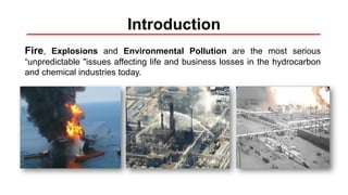
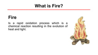
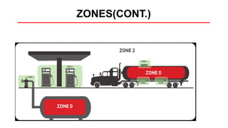
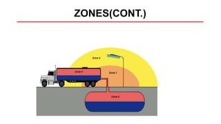
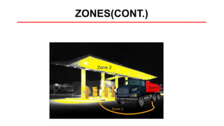
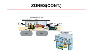
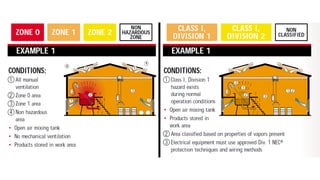
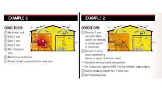
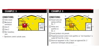
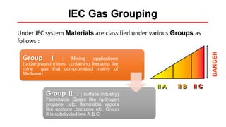
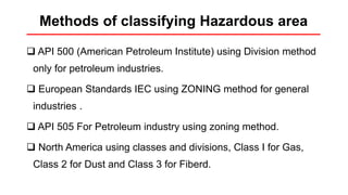
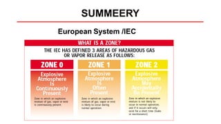
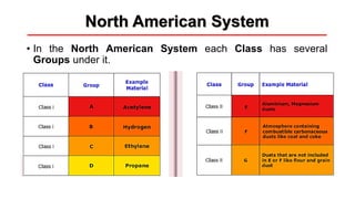
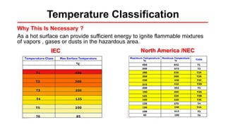
Hazardous Area
Classification
Introduction
Fire, Explosions and Environmental Pollution are the most serious
“unpredictable "issues affecting life and business losses in the hydrocarbon
and chemical industries today.
Fire and Explosion Fundamentals
• What is Fire?
• Flammable Hazardous Material
• Fire Triangle and Fire Tetrahedron
• What is an Explosion?
• Properties of Hazardous Materials
What is Fire?
Fire
Is a rapid oxidation process which is a
chemical reaction resulting in the evolution of
heat and light.
Flammable or hazardous material
• Flammable Material can be gas , vapor , liquid or solid that can react
continuously with oxygen and may result in fire or explosion.
• This reaction can be initiated by Spark or Hot Surfaces
• Flammable Materials can be:
• Flammable vapors generated by liquid
• Flammable Mists
• Flammable Gases
• Combustible Dusts
Paint
Flammable
Vapor
Fire Triangle
 Fuel
 Heat
 Oxygen
All three elements must be
present to initiate a fire.
 Fuel
 Heat
 Oxygen
 Chemical reaction
Fire Tetrahedron
May be the combustible
material. Can be solid ,liquid
or gas
Those materials that yield
oxygen or other Oxidizing
gases during the course of
a chemical reaction.
Heat is the energy
component needed to
increase the fuel’s
temperature to the point
where sufficient vapors are
produced for ignition to
occur.
The chemical chain reaction
known as fire occurs when
fuel, oxygen and heat are
present in the right
conditions and amount.
FUEL OXIDIZING AGENT (O2) HEAT
CHEMICAL CHAIN
REACTION
Fire Tetrahedron
What is an Explosion?
Explosion
is an uncontrolled release of energy
accompanied by a sudden and
violent expansion of gases and
possibly rapid combustion of any
flammable materials present.
Explosion
Properties of Hazardous Materials
Flammability Range
The minimum or maximum concentration
of gas in air that will ignite.
Lower Flammability Limit
The lowest concentration at which a
fuel/air mixture will burn. Below this there
is too little fuel (the mixture is too lean)
Upper Flammability Limit
The highest concentration at which a
fuel/air mixture will burn. Above this there
is not enough oxygen (the mixture is too
rich)
Properties of Hazardous Materials
Flash Point
The minimum temperature to which a liquid fuel gives off sufficient vapor that
can be ignited momentarily by a flame.
Fire Point
The minimum temperature to which a liquid fuel gives off sufficient vapor to
support continuous combustion.
Auto Ignition Temperature
The minimum temperature at which a liquid fuel will ignite without the presence
of a pilot flame or spark.
What is Hazardous Area?
The area in which an explosive gas
atmosphere present or likely to be
present in quantities such as to
require specific precautions for
construction, installation and use of
electrical apparatus.
HAC is Defined by three main criteria:
What is Hazardous Area?
Type of the hazard ( gas , vapor, dust, fibers)
Likelihood of the hazard being present in
flammable concentrations
The Auto Ignition Temperature of the
hazardous temperature.
Why do we classify Hazardous Areas?
• If proper area classification and safety engineering practices are followed
while working in those areas we can greatly reduce the risk of fire and
explosions hazards in these places.
• All electrical equipment produce energy in the form of sparks which can
ignite these hazardous materials and or cause explosions causing
catastrophic damage .
• In hazardous area we use special purpose explosion protected electrical
equipment and instruments.
Concept of Classification
• Hazardous Area Classification is to be done for the areas of the plant that
would have instances of flammable mixtures of vapors ,gases or dusts in
normal day to day operations.
• Under unusual conditions like a catastrophic accidental release of large
quantity of inflammable which are not easily predictable.
• Under usual day to day operational conditions in the plant or facility there
are some areas which would have the presence of flammable mixtures of
vapors and gases e.g.. Vapor space in the storage tank, around a
mechanical seal of a pump , the area around surrounding the breathing
valve on the storage tank.
Basic concepts
• What is Hazard?
• What is Risk?
• Can we avoid the risk altogether?
• Area classification – a measure of the risk
• Area classification benefits.
• How does Area Classification work?
• How can area classification reduce the costs?
HAZARD & RISK
Hazard
is the source of potential damage, harm or
adverse health effects. A hazard can exist
without incurring any harm.
NO EXPOSURE: NO RISK
21
What is the risk?
• Is the measure of likelihood that the undesired event or accident
will actually occur
Can we avoid the risk altogether?
• It is not possible in the world without some amount of risk
Hierarchy of Control
• Since we cannot avoid the risk we can manage it in a logical way.
• Since we have no control over the severity of the consequence , we
reduce the other factor in the risk equation which is the probability of
the occurrence.
• In the same way we manage the risk of handling and storing large
amounts of flammable and explosive materials by area classification
which reduce the probability of the materials catching fire or
explosion.
Can we avoid the risk altogether?
Area classification - A Measure of the Risk
• Hazardous Area Classification provides a
profile of the risk of explosion in these areas.
• It Cannot predict definitively that an explosion
will or will not take place in that area.
• It only segregates the plant areas into areas
where the likelihood of an explosion is high and
areas where the likelihood is low or improbable.
• The classification provides us a tool to mitigate
the risk of explosion in such areas.
How Does Area Classification Works ?
• Identify which areas of the plant are more hazardous and need
special attention or equipment.
• Identify areas of the plant carry more risks than others.
• Area classification allows the operations managers to
mitigate these risks by taking appropriate safety measures in
each identified areas and reduce the overall risk of the facility
• Design operations , material and staff movement to restrict
access to these areas and have special work procedures for
these areas.
Area Classification Benefits
• Give us a risk profile of the plant or facility to enable us to operate it
safer
• Enables top management to really understand the real risk of the facility
and then come up with appropriate strategies to mitigate the risk.
• Enable us to design and install electrical instrumentation and control
system equipment that will not cause fires or explosions at the optimum cost
• Reduce the costs of compliance to regulations and standards without
compromising on the safety
• Make the overall operations safer and more profitable
How Area Classification Reduce Costs?
• It tells us what kind of equipment can be used in the area and
what type cannot be used.
How
• Put explosion protected electrical equipment designed for
use only in certain area.
• The equipment carry marking which tells weather it can
be used or not.
• Based on this it will be safely use the equipment in that area
without any worry.
• There would be some electrical equipment and instruments
that are suitable for use only in zone 2 whereas certain
other types can be used safely in zone 1
Standards for Area Classification
• European System /IEC System ( Zones & Groups )
• North American System (NEC) ( Classes & Divisions )
IEC : International Electrotechnical Committee.
NEC : National Electric Code.
Standards for Area Classification
European System /IEC System
• The European System is based on zones
• Every Hazardous Area is broken up into different zones
based on the likelihood of a hazardous gas/vapor mixture
being present.
European System /IEC
Examples
Examples
European System (ZONES)
ZONES(CONT.)
ZONES(CONT.)
ZONES(CONT)
ZONES(CONT.)
ZONES(CONT.)
ZONES(CONT.)
ZONES(CONT.)
ZONES(CONT.)
ZONES(CONT.)
ZONES(CONT.)
ZONES(CONT.)
ZONES(CONT.)
ZONES(CONT.)
ZONES(CONT.)
Floating roof tank
Openings classification
• Openings are classified as A, B, C, D with the following characteristics:
• Type A – Openings not conforming to the characteristics specified for types B, C or D
• Examples:
• open passages for access or utilities, for example, ducts, pipes through walls, ceilings and
floors;
• fixed ventilation outlets in rooms, buildings and similar openings of types B, C and D which
are opened frequently or for long periods.
Openings classification(cont.)
• Openings are classified as A, B, C, D with the following characteristics:
• Type B – Openings which are normally closed (for example, automatic closing)
and infrequently opened, and which are close-fitting.
Openings classification(cont.)
• Type C – Openings normally closed and infrequently opened, conforming to type B,
which are also fitted with sealing devices (for example, a gasket) along the whole
perimeter; or two type B openings in series, having independent automatic closing
devices.
Openings classification(cont.)
• Openings are classified as A, B, C, D with the following characteristics:
• Type D – Openings normally closed conforming to type C which can only be opened
by special means or in an emergency.
IEC Gas Grouping
II C
DANGER
II B
II A
Under IEC system Materials are classified under various Groups as
follows :
Group I : Mining applications
(underground mines containing firedamp the
mine gas that compromised mainly of
Methane)
Group II :: ( surface industry)
Flammable Gases like hydrogen
propane ..etc. flammable vapors
like acetone ,benzene etc. Group
II is subdivided into A,B,C
IEC Gas Grouping
North American System/ NEC
• This system consists of Classes , Divisions & Groups:
Class I :locations in which flammable gases,
flammable liquids-produced vapors are or may be
present in the air in quantities sufficient to produce
explosive or ignitable mixtures ,
Class II :locations that are hazardous
because of present of combustible dust.
Class III :locations that are hazardous
because of the presence of easily ignitable
fibers.
North American System/NEC
• The NEC System is based on Divisions
Division 1
• In which ignitable concentrations of hazard
exists under normal operation conditions
and/or where hazard is caused by frequent
maintenance or repair work or frequent
equipment failure.
Division 2 • In which ignitable concentrations of hazard are
handled, processed or used, but which are
normally in closed containers or closed
systems from which they can only escape
through accidental rupture or breakdown of
such containers or systems.
North American System
• In the North American System each Class has several
Groups under it.
Material Classification under the two systems
Temperature Classification
Why This Is Necessary ?
As a hot surface can provide sufficient energy to ignite flammable mixtures
of vapors , gases or dusts in the hazardous area.
IEC North America /NEC
Protection Techniques
Popular Types
Exd: Flame/Explosion Proof
Exi: Intrinsically safe
Exe: Increased safety
Exn: No-sparking
Exp: Pressurization
Not - Popular Types
Exq: Powder Filled
Exo: Oil Immersed
Protection Techniques
Flameproof enclosure “ d ”
• is totally enclosed construction.
• When gas or vapor get into the enclosure and an
explosion take place,
• the enclosure withstands the pressure of explosion
and,
• preventing the ignition of a specified gas or vapor
surrounding the enclosure by sparks, flashes, or
explosion of the gas or vapor within, and which
operates at such an external temperature that a
surrounding flammable atmosphere will not be
ignited thereby.
Application:
switchgear, motors, Machine Control Systems
Protection Techniques
Increased Safety “ e ”
• IN case of INCREASED SAFETY CONCEPT
additional measures are applied to increase the level
of safety,
• thus preventing the possibility of high temperatures
and the occurrence of sparks or electric arcs within the
enclosure or on exposed parts of electrical equipment
• “Increased safety” increases the insulation
performance
Application :
Junction boxes/terminal boxes - Lighting - Measuring
instruments - Transformers - Squirrel cage motors
Methods of protection
The “e” Principal
insulated enclosure,
minimum IP 54
Ex certified electrical components
(with electrical connections that
cannot loosen by themselves)
Protection Techniques
Methods of protection
“de” protection
Protection Techniques
• Mainly junction boxes have 100% increased safety “e”
• Sparking equipment often incorporates “d ” components
• Most products commonly referred to as “e” combine the 2 types of
protection “e+d”
Methods of protection
“de” products
also called «ed»
flameproof “d” chambers
“e” enclosure
16A plug and socket
Protection Techniques
Methods of protection
“de” products
also called «ed»
Control stations
Protection Techniques
Methods of protection
“de” products
also called «ed»
fluorescent luminaire
Protection Techniques
Methods of protection
stainless steel - “e” (junction box)
cabinet - “de” (control station)
“de” products
also called «ed»
Protection Techniques
Intrinsically safe “ i ”
• Electrical system /apparatus and its wiring is not capable of realizing sufficient
electrical or thermal energy under normal or abnormal conditions to cause ignition
of a specific flammable or combustible mixture in its most ignitable concentrations.
Ex ia
Equipment that incapable of causing
ignition in normal operation with two
faults
Ex ib
Equipment incapable of causing
ignition in normal operation with a
single fault
Intrinsically
safe “ i ”
e.g. switch amplifier
Protection Techniques
Pressurization type “ p ”
• is a type of protection by which the entry of a
surrounding atmosphere into the enclosure of the
electrical apparatus is prevented by maintaining,
• inside the said enclosure, a protective gas at a
higher pressure than that of the surrounding
atmosphere.
• The over pressure is maintained with or without
continuous flow of the protective gas.
• The protective gas can be either air, inert gas or an
other suitable gas.
Protection Techniques
Pressurization type “ p ”
Application:
• Large machines
• Switching and M&C panels
• Switch rooms & control centers
• Analysis & monitoring apparatus
• Special application solutions
Protection Techniques
No – sparking “n”
It is applicable to electric equipment which is not capable of igniting potentially
explosive atmospheres under normal operation.
is the special explosion protection construction for Zone 2 or Division 2.
Protection Techniques
Powder Filled “q”
is a type of protection in which the enclosure of the electrical
apparatus is filled with a material in a finely granulated
state so that, in the intended conditions of service, any arc
occurring within the enclosure of the electrical apparatus
will not ignite the surrounding atmosphere.
No ignition shall be caused either by flame or by excessive
temperature of the surfaces of the enclosure.
Application :
• Fuses
• Capacitors
• Electronic circuit boards - EVG
Protection Techniques
Oil immersion “o”
• is a type of protection in which the electrical
apparatus or parts of the electrical apparatus are
immersed in oil
• in such a way that an explosive atmosphere which
may be above the oil or outside the enclosure
cannot be ignited.
Application :
• Switching units
• Circuit breakers
• Transformers
Protection Techniques
Encapsulation “m”
• is a type of protection, in which the parts that could
ignite an explosive atmosphere,
• are enclosed in a resin sufficiently resistant to
environmental influences,
• in such a way that this explosive atmosphere cannot be
ignited either by sparking or heating which may
occur within the encapsulation.
Application :
• Valves
• Electronic circuit boards
• Miniature motors
 API 500 (American Petroleum Institute) using Division method
only for petroleum industries.
 European Standards IEC using ZONING method for general
industries .
 API 505 For Petroleum industry using zoning method.
 North America using classes and divisions, Class I for Gas,
Class 2 for Dust and Class 3 for Fiberd.
Methods of classifying Hazardous area
CENELEC: European committee for electrotechnical standardization
Ex Marking
Ex Marking
ATEX MARKING SYSTEM
ATEX: Explosive Atmosphere
Installation rules
Methods of installation throughout the world
• wire, braid or steel-tape
armoured cable.
• connection using an earth
continuity cable gland
• unarmoured cable
• connection using a cable gland
• conductors placed inside a
rigid threaded conduit
• connection using a seal
Installation rules
Multicore cables
Protection against mechanical shocks
• armoured cables
Or • cable ducting + installation clamps
Protection against chemical attack
• most industrial cables are suitable
Protection against fire
• minimum: cable which does not propagate flames
• ideal : cable capable of withstanding fire
Methods of installation throughout the world
Installation rules
Selecting cable inlets
The cable gland must:
• be adapted to the type of thread of the product on which it is
mounted
• be Exe or Exd certified
• have at least the same index of protection as the product on
which it is mounted
• be adapted to the cable diameter and type
• sometimes clamp the cable
Methods of installation throughout the world
Installation rules
Selecting cable glands
The cable gland must be certified:
• Exe if the enclosure is Exe or Exed
• Exd if the enclosure is Exd
IP of the cable gland ≥ IP of the product ( later will be explained)
Methods of installation throughout the world
Installation rules
Selecting cable glands
The cable gland must be matched to the cable type
• Cable diameter
• Cable .armoured
or .unarmoured
or .MICC
Mineral-insulated copper-clad cable
Methods of installation throughout the world
Selecting cable glands
The cable must be correctly clamped by means of the
cable gland
• Internal clamping system
• External clamping system
or by means of an installation clamp
Methods of installation throughout the world
cable clamp
Selecting
cable glands
“e” cable gland
• polycarbonate
• IP 67
• for unarmoured cable
Methods of installation throughout the world
Selecting
cable glands
“e” plastic cable gland
unarmoured cable
“ed” 16A 230V socket
Methods of installation throughout the world
Selecting cable glands
“ed” rotary switch
armoured cable
“e” cable gland for
an armoured cable
Methods of installation throughout the world
Installation rules
Selecting cable glands
cable clamping
rings
“e” cable gland for an armoured cable
and earth continuity
NB: this type of gland ensures the earth continuity of the armoured cable
Methods of installation throughout the world
Installation rules
Selecting cable glands
“d” cable gland
Methods of installation throughout the world
Installation rules
Selecting cable glands
seal
Compound
• The connection between the
conduit and the electrical
device is achieved using a
seal
• The connector is filled with a
sealing compound (to prevent
an explosion from spreading
through the conduits)
Methods of installation throughout the world
Installation rules
Advantages of an installation with cable glands
compared to a conduit installation
• More competitive prices
• No need to thread the conduits on site
• No generalized seals
• Easier maintenance, inspection and extensions
• Far fewer problems with corrosion
Methods of installation throughout the world
Conduit installation
Installationwith cable gland
What do you think?
EX !!!
What do you think?
EX !!!
Ingress Protection
• IP classification system designates the
degree of protection provided by an
enclosure against impact and water or
dust penetration (ingress).
• It has two numbers;
• First: Protection against solid objects,
• second: Protection against water.
Ingres Protection
EXAMPLE: IP 54
IP Rating
IP Rating
IP ratings
What if hazardous area is wrongly classified ?
Unnecessarily pay more money
More Maintenance Costs
Facility will incur more costs over its lifecycle.
Cost could be high as they may result in unwanted
explosion leading to loss of life and property
 API 500 (American Petroleum Institute) using Division method
only for petroleum industries.
 European Standards IEC using ZONING method for general
industries .
 API 505 For Petroleum industry using zoning method.
 North America using classes and divisions, Class I for Gas,
Class 2 for Dust and Class 3 for Fiberd.
Methods of classifying Hazardous area
SUMMEERY
European System /IEC
North American System/ NEC
• This system consists of Classes , Divisions & Groups:
Class I :locations in which flammable gases,
flammable liquids-produced vapors are or may be
present in the air in quantities sufficient to produce
explosive or ignitable mixtures ,
Class II :locations that are hazardous
because of present of combustible dust.
Class III :locations that are hazardous
because of the presence of easily ignitable
fibers.
North American System
• In the North American System each Class has several
Groups under it.
Temperature Classification
Why This Is Necessary ?
As a hot surface can provide sufficient energy to ignite flammable mixtures
of vapors , gases or dusts in the hazardous area.
IEC North America /NEC
CENELEC: European committee for electrotechnical standardization
Ex Marking
Ex Marking
ATEX MARKING SYSTEM
ATEX: Explosive Atmosphere
NEC Marking
Ingres Protection
EXAMPLE: IP 54
How to carry out area classification?
Step by step
STEP 1 :
Decide on the standard that would be followed (IEC- NEC)
STEP 2 :
Check out the lay out of the facility or the plant, the quantities that are
handled in the process plant
STEP 3 :
what is the material temperature classification of these materials ?flash points,
auto ignition temperature, density of vapor/ gas (lighter or heavier than air)
How to carry out Area Classification?
Step by step
STEP 4 :
• Divide the plant into different units
• Start to evaluate the sources of release of unit
• Classify them as continuous grade, primary grade or secondary grade
• Tabulate them findings in a worksheet and mark these on the general
arrangement drawing of the unit
STEP 5 :
Evaluate ventilation in the area (closed or open) how does the wind go? Does the
wind direction remain the same or changed if the vapor cloud formed , how far it
will travel along with the wind ? Are there are any places where escaped vapors
may accumulate
Sources of
release
How to carry out Area Classification?
Step by step
STEP 6 :
based on the findings on step 4&5 and the standard you are following
mark the hazardous area on the drawings these extents will be
surrounding the release points that have been marked in step4
STEP 7 :
Divide the hazardous area into divisions or zones ( depending on the standard
you are using)
Consequence of Poor area classification
• Over Classification – White Elephant
• Under Classification – Playing with Fire
• Proper Area Classification is the virtuous in between
Over classification- A White Elephant
• Increase capital expenditure on new projects due to more
expensive equipment being specified
• Increase operations and maintenance expenditure of an
existing facility as replacement parts will become more expensive
maintenance work permits will be stringent and time consuming
leading to higher costs
• Unnecessary label your facility dangerous in the local
community
• Increase your insurance premiums
Under classification – Playing With Fire
• Increase The Risks of your plant or facility without anybody
knowing it, especially the top management.
• In case of an unfortunate accident expose you and your
company to lawsuits.
• Give lot of bad press to your company and even threaten its
existence
So now what do we do?
• Conduct an Audit of your Facility.
• Marking Hazardous Areas with reference to the current
standards.
• Training personnel on the basics of HAC.

Presentation Hazardous Area Classification.pdf

  • 1.
  • 2.
    Introduction Fire, Explosions andEnvironmental Pollution are the most serious “unpredictable "issues affecting life and business losses in the hydrocarbon and chemical industries today.
  • 3.
    Fire and ExplosionFundamentals • What is Fire? • Flammable Hazardous Material • Fire Triangle and Fire Tetrahedron • What is an Explosion? • Properties of Hazardous Materials
  • 4.
    What is Fire? Fire Isa rapid oxidation process which is a chemical reaction resulting in the evolution of heat and light.
  • 5.
    Flammable or hazardousmaterial • Flammable Material can be gas , vapor , liquid or solid that can react continuously with oxygen and may result in fire or explosion. • This reaction can be initiated by Spark or Hot Surfaces • Flammable Materials can be: • Flammable vapors generated by liquid • Flammable Mists • Flammable Gases • Combustible Dusts Paint Flammable Vapor
  • 6.
    Fire Triangle  Fuel Heat  Oxygen All three elements must be present to initiate a fire.
  • 7.
     Fuel  Heat Oxygen  Chemical reaction Fire Tetrahedron
  • 8.
    May be thecombustible material. Can be solid ,liquid or gas Those materials that yield oxygen or other Oxidizing gases during the course of a chemical reaction. Heat is the energy component needed to increase the fuel’s temperature to the point where sufficient vapors are produced for ignition to occur. The chemical chain reaction known as fire occurs when fuel, oxygen and heat are present in the right conditions and amount. FUEL OXIDIZING AGENT (O2) HEAT CHEMICAL CHAIN REACTION Fire Tetrahedron
  • 9.
    What is anExplosion? Explosion is an uncontrolled release of energy accompanied by a sudden and violent expansion of gases and possibly rapid combustion of any flammable materials present.
  • 10.
  • 11.
    Properties of HazardousMaterials Flammability Range The minimum or maximum concentration of gas in air that will ignite. Lower Flammability Limit The lowest concentration at which a fuel/air mixture will burn. Below this there is too little fuel (the mixture is too lean) Upper Flammability Limit The highest concentration at which a fuel/air mixture will burn. Above this there is not enough oxygen (the mixture is too rich)
  • 12.
    Properties of HazardousMaterials Flash Point The minimum temperature to which a liquid fuel gives off sufficient vapor that can be ignited momentarily by a flame. Fire Point The minimum temperature to which a liquid fuel gives off sufficient vapor to support continuous combustion. Auto Ignition Temperature The minimum temperature at which a liquid fuel will ignite without the presence of a pilot flame or spark.
  • 13.
    What is HazardousArea? The area in which an explosive gas atmosphere present or likely to be present in quantities such as to require specific precautions for construction, installation and use of electrical apparatus.
  • 14.
    HAC is Definedby three main criteria: What is Hazardous Area? Type of the hazard ( gas , vapor, dust, fibers) Likelihood of the hazard being present in flammable concentrations The Auto Ignition Temperature of the hazardous temperature.
  • 15.
    Why do weclassify Hazardous Areas? • If proper area classification and safety engineering practices are followed while working in those areas we can greatly reduce the risk of fire and explosions hazards in these places. • All electrical equipment produce energy in the form of sparks which can ignite these hazardous materials and or cause explosions causing catastrophic damage . • In hazardous area we use special purpose explosion protected electrical equipment and instruments.
  • 16.
    Concept of Classification •Hazardous Area Classification is to be done for the areas of the plant that would have instances of flammable mixtures of vapors ,gases or dusts in normal day to day operations. • Under unusual conditions like a catastrophic accidental release of large quantity of inflammable which are not easily predictable. • Under usual day to day operational conditions in the plant or facility there are some areas which would have the presence of flammable mixtures of vapors and gases e.g.. Vapor space in the storage tank, around a mechanical seal of a pump , the area around surrounding the breathing valve on the storage tank.
  • 17.
    Basic concepts • Whatis Hazard? • What is Risk? • Can we avoid the risk altogether? • Area classification – a measure of the risk • Area classification benefits. • How does Area Classification work? • How can area classification reduce the costs?
  • 18.
    HAZARD & RISK Hazard isthe source of potential damage, harm or adverse health effects. A hazard can exist without incurring any harm. NO EXPOSURE: NO RISK 21
  • 19.
    What is therisk? • Is the measure of likelihood that the undesired event or accident will actually occur
  • 20.
    Can we avoidthe risk altogether? • It is not possible in the world without some amount of risk
  • 21.
  • 22.
    • Since wecannot avoid the risk we can manage it in a logical way. • Since we have no control over the severity of the consequence , we reduce the other factor in the risk equation which is the probability of the occurrence. • In the same way we manage the risk of handling and storing large amounts of flammable and explosive materials by area classification which reduce the probability of the materials catching fire or explosion. Can we avoid the risk altogether?
  • 23.
    Area classification -A Measure of the Risk • Hazardous Area Classification provides a profile of the risk of explosion in these areas. • It Cannot predict definitively that an explosion will or will not take place in that area. • It only segregates the plant areas into areas where the likelihood of an explosion is high and areas where the likelihood is low or improbable. • The classification provides us a tool to mitigate the risk of explosion in such areas.
  • 24.
    How Does AreaClassification Works ? • Identify which areas of the plant are more hazardous and need special attention or equipment. • Identify areas of the plant carry more risks than others. • Area classification allows the operations managers to mitigate these risks by taking appropriate safety measures in each identified areas and reduce the overall risk of the facility • Design operations , material and staff movement to restrict access to these areas and have special work procedures for these areas.
  • 25.
    Area Classification Benefits •Give us a risk profile of the plant or facility to enable us to operate it safer • Enables top management to really understand the real risk of the facility and then come up with appropriate strategies to mitigate the risk. • Enable us to design and install electrical instrumentation and control system equipment that will not cause fires or explosions at the optimum cost • Reduce the costs of compliance to regulations and standards without compromising on the safety • Make the overall operations safer and more profitable
  • 26.
    How Area ClassificationReduce Costs? • It tells us what kind of equipment can be used in the area and what type cannot be used. How • Put explosion protected electrical equipment designed for use only in certain area. • The equipment carry marking which tells weather it can be used or not. • Based on this it will be safely use the equipment in that area without any worry. • There would be some electrical equipment and instruments that are suitable for use only in zone 2 whereas certain other types can be used safely in zone 1
  • 27.
    Standards for AreaClassification • European System /IEC System ( Zones & Groups ) • North American System (NEC) ( Classes & Divisions ) IEC : International Electrotechnical Committee. NEC : National Electric Code.
  • 28.
    Standards for AreaClassification European System /IEC System • The European System is based on zones • Every Hazardous Area is broken up into different zones based on the likelihood of a hazardous gas/vapor mixture being present.
  • 29.
  • 30.
  • 31.
  • 33.
  • 34.
  • 35.
  • 36.
  • 37.
  • 38.
  • 39.
  • 40.
  • 41.
  • 42.
  • 43.
  • 44.
  • 45.
  • 46.
  • 47.
  • 48.
  • 51.
  • 53.
    Openings classification • Openingsare classified as A, B, C, D with the following characteristics: • Type A – Openings not conforming to the characteristics specified for types B, C or D • Examples: • open passages for access or utilities, for example, ducts, pipes through walls, ceilings and floors; • fixed ventilation outlets in rooms, buildings and similar openings of types B, C and D which are opened frequently or for long periods.
  • 54.
    Openings classification(cont.) • Openingsare classified as A, B, C, D with the following characteristics: • Type B – Openings which are normally closed (for example, automatic closing) and infrequently opened, and which are close-fitting.
  • 55.
    Openings classification(cont.) • TypeC – Openings normally closed and infrequently opened, conforming to type B, which are also fitted with sealing devices (for example, a gasket) along the whole perimeter; or two type B openings in series, having independent automatic closing devices.
  • 56.
    Openings classification(cont.) • Openingsare classified as A, B, C, D with the following characteristics: • Type D – Openings normally closed conforming to type C which can only be opened by special means or in an emergency.
  • 61.
    IEC Gas Grouping IIC DANGER II B II A Under IEC system Materials are classified under various Groups as follows : Group I : Mining applications (underground mines containing firedamp the mine gas that compromised mainly of Methane) Group II :: ( surface industry) Flammable Gases like hydrogen propane ..etc. flammable vapors like acetone ,benzene etc. Group II is subdivided into A,B,C
  • 62.
  • 63.
    North American System/NEC • This system consists of Classes , Divisions & Groups: Class I :locations in which flammable gases, flammable liquids-produced vapors are or may be present in the air in quantities sufficient to produce explosive or ignitable mixtures , Class II :locations that are hazardous because of present of combustible dust. Class III :locations that are hazardous because of the presence of easily ignitable fibers.
  • 65.
    North American System/NEC •The NEC System is based on Divisions Division 1 • In which ignitable concentrations of hazard exists under normal operation conditions and/or where hazard is caused by frequent maintenance or repair work or frequent equipment failure. Division 2 • In which ignitable concentrations of hazard are handled, processed or used, but which are normally in closed containers or closed systems from which they can only escape through accidental rupture or breakdown of such containers or systems.
  • 66.
    North American System •In the North American System each Class has several Groups under it.
  • 67.
  • 69.
    Temperature Classification Why ThisIs Necessary ? As a hot surface can provide sufficient energy to ignite flammable mixtures of vapors , gases or dusts in the hazardous area. IEC North America /NEC
  • 71.
    Protection Techniques Popular Types Exd:Flame/Explosion Proof Exi: Intrinsically safe Exe: Increased safety Exn: No-sparking Exp: Pressurization Not - Popular Types Exq: Powder Filled Exo: Oil Immersed
  • 72.
    Protection Techniques Flameproof enclosure“ d ” • is totally enclosed construction. • When gas or vapor get into the enclosure and an explosion take place, • the enclosure withstands the pressure of explosion and, • preventing the ignition of a specified gas or vapor surrounding the enclosure by sparks, flashes, or explosion of the gas or vapor within, and which operates at such an external temperature that a surrounding flammable atmosphere will not be ignited thereby. Application: switchgear, motors, Machine Control Systems
  • 73.
    Protection Techniques Increased Safety“ e ” • IN case of INCREASED SAFETY CONCEPT additional measures are applied to increase the level of safety, • thus preventing the possibility of high temperatures and the occurrence of sparks or electric arcs within the enclosure or on exposed parts of electrical equipment • “Increased safety” increases the insulation performance Application : Junction boxes/terminal boxes - Lighting - Measuring instruments - Transformers - Squirrel cage motors
  • 74.
    Methods of protection The“e” Principal insulated enclosure, minimum IP 54 Ex certified electrical components (with electrical connections that cannot loosen by themselves) Protection Techniques
  • 75.
    Methods of protection “de”protection Protection Techniques • Mainly junction boxes have 100% increased safety “e” • Sparking equipment often incorporates “d ” components • Most products commonly referred to as “e” combine the 2 types of protection “e+d”
  • 76.
    Methods of protection “de”products also called «ed» flameproof “d” chambers “e” enclosure 16A plug and socket Protection Techniques
  • 77.
    Methods of protection “de”products also called «ed» Control stations Protection Techniques
  • 78.
    Methods of protection “de”products also called «ed» fluorescent luminaire Protection Techniques
  • 79.
    Methods of protection stainlesssteel - “e” (junction box) cabinet - “de” (control station) “de” products also called «ed» Protection Techniques
  • 80.
    Protection Techniques Intrinsically safe“ i ” • Electrical system /apparatus and its wiring is not capable of realizing sufficient electrical or thermal energy under normal or abnormal conditions to cause ignition of a specific flammable or combustible mixture in its most ignitable concentrations. Ex ia Equipment that incapable of causing ignition in normal operation with two faults Ex ib Equipment incapable of causing ignition in normal operation with a single fault Intrinsically safe “ i ” e.g. switch amplifier
  • 81.
    Protection Techniques Pressurization type“ p ” • is a type of protection by which the entry of a surrounding atmosphere into the enclosure of the electrical apparatus is prevented by maintaining, • inside the said enclosure, a protective gas at a higher pressure than that of the surrounding atmosphere. • The over pressure is maintained with or without continuous flow of the protective gas. • The protective gas can be either air, inert gas or an other suitable gas.
  • 82.
    Protection Techniques Pressurization type“ p ” Application: • Large machines • Switching and M&C panels • Switch rooms & control centers • Analysis & monitoring apparatus • Special application solutions
  • 83.
    Protection Techniques No –sparking “n” It is applicable to electric equipment which is not capable of igniting potentially explosive atmospheres under normal operation. is the special explosion protection construction for Zone 2 or Division 2.
  • 84.
    Protection Techniques Powder Filled“q” is a type of protection in which the enclosure of the electrical apparatus is filled with a material in a finely granulated state so that, in the intended conditions of service, any arc occurring within the enclosure of the electrical apparatus will not ignite the surrounding atmosphere. No ignition shall be caused either by flame or by excessive temperature of the surfaces of the enclosure. Application : • Fuses • Capacitors • Electronic circuit boards - EVG
  • 85.
    Protection Techniques Oil immersion“o” • is a type of protection in which the electrical apparatus or parts of the electrical apparatus are immersed in oil • in such a way that an explosive atmosphere which may be above the oil or outside the enclosure cannot be ignited. Application : • Switching units • Circuit breakers • Transformers
  • 86.
    Protection Techniques Encapsulation “m” •is a type of protection, in which the parts that could ignite an explosive atmosphere, • are enclosed in a resin sufficiently resistant to environmental influences, • in such a way that this explosive atmosphere cannot be ignited either by sparking or heating which may occur within the encapsulation. Application : • Valves • Electronic circuit boards • Miniature motors
  • 88.
     API 500(American Petroleum Institute) using Division method only for petroleum industries.  European Standards IEC using ZONING method for general industries .  API 505 For Petroleum industry using zoning method.  North America using classes and divisions, Class I for Gas, Class 2 for Dust and Class 3 for Fiberd. Methods of classifying Hazardous area
  • 89.
    CENELEC: European committeefor electrotechnical standardization Ex Marking
  • 90.
    Ex Marking ATEX MARKINGSYSTEM ATEX: Explosive Atmosphere
  • 91.
    Installation rules Methods ofinstallation throughout the world • wire, braid or steel-tape armoured cable. • connection using an earth continuity cable gland • unarmoured cable • connection using a cable gland • conductors placed inside a rigid threaded conduit • connection using a seal
  • 92.
    Installation rules Multicore cables Protectionagainst mechanical shocks • armoured cables Or • cable ducting + installation clamps Protection against chemical attack • most industrial cables are suitable Protection against fire • minimum: cable which does not propagate flames • ideal : cable capable of withstanding fire Methods of installation throughout the world
  • 93.
    Installation rules Selecting cableinlets The cable gland must: • be adapted to the type of thread of the product on which it is mounted • be Exe or Exd certified • have at least the same index of protection as the product on which it is mounted • be adapted to the cable diameter and type • sometimes clamp the cable Methods of installation throughout the world
  • 94.
    Installation rules Selecting cableglands The cable gland must be certified: • Exe if the enclosure is Exe or Exed • Exd if the enclosure is Exd IP of the cable gland ≥ IP of the product ( later will be explained) Methods of installation throughout the world
  • 95.
    Installation rules Selecting cableglands The cable gland must be matched to the cable type • Cable diameter • Cable .armoured or .unarmoured or .MICC Mineral-insulated copper-clad cable Methods of installation throughout the world
  • 96.
    Selecting cable glands Thecable must be correctly clamped by means of the cable gland • Internal clamping system • External clamping system or by means of an installation clamp Methods of installation throughout the world
  • 97.
    cable clamp Selecting cable glands “e”cable gland • polycarbonate • IP 67 • for unarmoured cable Methods of installation throughout the world
  • 98.
    Selecting cable glands “e” plasticcable gland unarmoured cable “ed” 16A 230V socket Methods of installation throughout the world
  • 99.
    Selecting cable glands “ed”rotary switch armoured cable “e” cable gland for an armoured cable Methods of installation throughout the world
  • 100.
    Installation rules Selecting cableglands cable clamping rings “e” cable gland for an armoured cable and earth continuity NB: this type of gland ensures the earth continuity of the armoured cable Methods of installation throughout the world
  • 101.
    Installation rules Selecting cableglands “d” cable gland Methods of installation throughout the world
  • 102.
    Installation rules Selecting cableglands seal Compound • The connection between the conduit and the electrical device is achieved using a seal • The connector is filled with a sealing compound (to prevent an explosion from spreading through the conduits) Methods of installation throughout the world
  • 103.
    Installation rules Advantages ofan installation with cable glands compared to a conduit installation • More competitive prices • No need to thread the conduits on site • No generalized seals • Easier maintenance, inspection and extensions • Far fewer problems with corrosion Methods of installation throughout the world
  • 104.
  • 105.
  • 106.
    What do youthink? EX !!!
  • 107.
    What do youthink? EX !!!
  • 108.
    Ingress Protection • IPclassification system designates the degree of protection provided by an enclosure against impact and water or dust penetration (ingress). • It has two numbers; • First: Protection against solid objects, • second: Protection against water.
  • 109.
  • 110.
  • 111.
  • 112.
  • 113.
    What if hazardousarea is wrongly classified ? Unnecessarily pay more money More Maintenance Costs Facility will incur more costs over its lifecycle. Cost could be high as they may result in unwanted explosion leading to loss of life and property
  • 114.
     API 500(American Petroleum Institute) using Division method only for petroleum industries.  European Standards IEC using ZONING method for general industries .  API 505 For Petroleum industry using zoning method.  North America using classes and divisions, Class I for Gas, Class 2 for Dust and Class 3 for Fiberd. Methods of classifying Hazardous area
  • 115.
  • 116.
    North American System/NEC • This system consists of Classes , Divisions & Groups: Class I :locations in which flammable gases, flammable liquids-produced vapors are or may be present in the air in quantities sufficient to produce explosive or ignitable mixtures , Class II :locations that are hazardous because of present of combustible dust. Class III :locations that are hazardous because of the presence of easily ignitable fibers.
  • 117.
    North American System •In the North American System each Class has several Groups under it.
  • 119.
    Temperature Classification Why ThisIs Necessary ? As a hot surface can provide sufficient energy to ignite flammable mixtures of vapors , gases or dusts in the hazardous area. IEC North America /NEC
  • 121.
    CENELEC: European committeefor electrotechnical standardization Ex Marking
  • 122.
    Ex Marking ATEX MARKINGSYSTEM ATEX: Explosive Atmosphere
  • 123.
  • 124.
  • 125.
    How to carryout area classification? Step by step STEP 1 : Decide on the standard that would be followed (IEC- NEC) STEP 2 : Check out the lay out of the facility or the plant, the quantities that are handled in the process plant STEP 3 : what is the material temperature classification of these materials ?flash points, auto ignition temperature, density of vapor/ gas (lighter or heavier than air)
  • 126.
    How to carryout Area Classification? Step by step STEP 4 : • Divide the plant into different units • Start to evaluate the sources of release of unit • Classify them as continuous grade, primary grade or secondary grade • Tabulate them findings in a worksheet and mark these on the general arrangement drawing of the unit STEP 5 : Evaluate ventilation in the area (closed or open) how does the wind go? Does the wind direction remain the same or changed if the vapor cloud formed , how far it will travel along with the wind ? Are there are any places where escaped vapors may accumulate
  • 127.
  • 128.
    How to carryout Area Classification? Step by step STEP 6 : based on the findings on step 4&5 and the standard you are following mark the hazardous area on the drawings these extents will be surrounding the release points that have been marked in step4 STEP 7 : Divide the hazardous area into divisions or zones ( depending on the standard you are using)
  • 129.
    Consequence of Poorarea classification • Over Classification – White Elephant • Under Classification – Playing with Fire • Proper Area Classification is the virtuous in between
  • 130.
    Over classification- AWhite Elephant • Increase capital expenditure on new projects due to more expensive equipment being specified • Increase operations and maintenance expenditure of an existing facility as replacement parts will become more expensive maintenance work permits will be stringent and time consuming leading to higher costs • Unnecessary label your facility dangerous in the local community • Increase your insurance premiums
  • 131.
    Under classification –Playing With Fire • Increase The Risks of your plant or facility without anybody knowing it, especially the top management. • In case of an unfortunate accident expose you and your company to lawsuits. • Give lot of bad press to your company and even threaten its existence
  • 132.
    So now whatdo we do? • Conduct an Audit of your Facility. • Marking Hazardous Areas with reference to the current standards. • Training personnel on the basics of HAC.