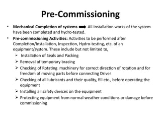
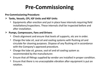
Procedure for Pre-Commissioning
& Commissioning of ETP
Project
Client
TPIA
Contractor
INDEX
• Introduction
• Systems & Equipments of ETP at Lingala
• Checklist
• Pre-Commissioning
• Pre Start Checks
• Start Up Procedure
• Shut Down Procedure
• Commissioning
• Performance Guarantee Test Run
INTRODUCTION
Introduction
Oil Wells
(Crude Oil +
Associated Gas)
ETP (Produced
Water from GGSs
for treatment i.e.,
removal of
Oil/Suspended
Solids)
Separators
(Separates
Liquid and
Gas)
Heater Treater
( Crude
Emulsion is
treated to
separate water
from crude oil)
Produced Water
(Effluent) (free
oil, emulsified
oil + dissolved&
suspended
solids +
impurities)
GGSs
SYSTEMS & EQUIPMENTS OF
ETP
Systems & Equipments of ETP
Raw Effluent
tanks
CPI Unit
Effluent Feed
Pumps
IGF Unit
Treated
Effluent
Booster Pumps
Skim Oil pumps
NSF Units
Nutshell Filters
Nutshell Filter
Backwash
pumps
Treated
Water Tanks
Treated Water
Transfer Pumps
Chemical Dosing
System
Deoiler-I Storage Vessels
Deoiler-I Injection Pumps
Scale Inhibitor Storage
Vessels
Scale Inhibitor Injection
Pumps
Deoiler-II Storage Vessels
Deoiler-II Injection Pumps
Dewatering Chemical
Storage Vessels
Dewatering Chemical
Injection Pumps
Instrument Air
Compressor
Package
Instrument Air
Compressors
Air Pre-Filters
Instrument Air Dryers
Air After-Filters
Instrument Air Receivers
Slop Oil System
Slop Oil Sump
Slop Oil Pumps
Slop Oil Tank
Slop Oil Transfer Pumps
Raw Water Transfer
Pumps
Sludge Handling
System
Wet Sludge Pit
Sludge Pumps
Thickner
Sludge Collection Sump
Sludge Feed Pumps
Centrifuge
Sludge Drying Bed
Gas Generator
Set
Systems & Equipments of ETP
CHECKLIST
Checklist
Vessels &
Storage Tanks
• Location, Orientation, Elevation of nozzles as per drawing
• Internal Installations as per drawing
• Tanks Internally for cleanliness
• All platforms and ladders provided for easy access
• Man way inspection
CPI, IGF &
NSF
• Internal Installations
• Internal pipes installation with correct bolts and gaskets
• Instrument nozzles, Vessel Nozzles in right location, clear and no obstruction
• Inspection of Vessels internally for cleanliness
• Inlet pipes and distribution pipes installation as per design Intent
Pumps
• Base Plate properly grouted to foundation
• Operation of suction and discharge valves
• Pump and Driver checks for freedom of movement
• Motor bearing lubrication
• Instrument alarms/shutdown settings
Checklist
Agitators
• Equipment Installation as per drawing
• Equipment cleanliness
• Free rotation of shaft in correct direction that rotor does not foul with tank internals
• Bolting lubrication
Dosing Pumps
• Installation damages
• Suction and discharge piping is clean and supported
• Motor rotation
• Coupling and coupling guard installation
Instrument air
compressors
• Compressor Lubrication
• All electrical connections are tight
• Rotation in the correct direction
PRE-COMMISSIONING
Pre-Commissioning
• Mechanical Completion of systems All Installation works of the system
have been completed and hydro-tested.
• Pre-commissioning Activities: Activities to be performed after
Completion/Installation, Inspection, Hydro-testing, etc. of an
equipment/system. These include but not limited to,
 Installation of Seals and Packing
 Removal of temporary bracing
 Checking of Rotating machinery for correct direction of rotation and for
freedom of moving parts before connecting Driver
 Checking of all lubricants and their quality, fill etc., before operating the
equipment
 Installing all safety devices on the equipment
 Protecting equipment from normal weather conditions or damage before
commissioning
Pre-Commissioning Procedure:
 Tanks, Vessels, CPI, IGF Units and NSF Units
• Equipments after erection and put in place have internals requiring field
installations/inspections. These internals shall be inspected before and
after installation.
 Pumps, Compressors, Fans and Drivers
• Check alignment and ensure that levels of supports, etc are in order.
• Charge the lube oil, seal oil and cooling systems with flushing oil and
circulate for cleaning purposes. Dispose of any flushing oil in accordance
with the Company’s approved procedure.
• Charge the lube oil, grease, seal oil and oil cooling system as
recommended by the manufacturer.
• Ensure that all fittings supplied by vendor are installed in proper condition.
• Ensure that there is no unacceptable vibration after equipment is put on
rotation.
Pre-Commissioning
Pre-Commissioning
Pre-Commissioning Procedure:
 Piping System
• Orifice Plates, Control Valves and any other online instruments should not
be installed before testing and flushing.
• Piping System shall be thoroughly flushed and cleaned to the satisfaction
of the company.
• Hydrostatically and pneumatically test all piping as required by the
drawings or specifications.
• Vents shall be provided at high points of loops and shall be plugged after
testing.
 Instrumentation System
• Functional Check of all instrument and controllers
• Checking positions of all valves as per drawings
• Checking of all electrical signals and alarm wiring fro continuity, correct
source of power and polarity
• Check all Shut down Systems before commissioning.
Pre-Commissioning
Pre-Commissioning Procedure:
 Electrical System
• To perform continuity test and Insulation Resistance Test for power and
control circuits.
• Earth continuity test for all circuits.
• Verification of phase sequence.
• Checking of Safety features for correctness of operation etc.
• Checking of all wired interface contacts for PLC at panel and equipment
terminal chambers as applicable.
• A close visual inspection of electrical equipment in hazardous areas shall be
made to ensure that equipment is suitable for the classified zone and gas
group and correctly installed, with all covers, bolts, nuts and hardware
intact and there is no physical damage mark seen on the enclosure.
PRE START CHECKS
Pre-Start Checks
• Ensure safety systems are in place.
• Ensure all the Utilities are available.
• Sufficient copies of Log Books should be ready.
• Required Quantity of Chemicals for one day should have to be shifted from Chemical store
room.
• Check the spare parts and Tools that are availability at site.
• Prepare the chemical in the dosing tanks as per the procedure laid down.
• Required parameters will be analyzed as per standard method of ASTM/IS code, check
availability of Lab instruments and chemicals accordingly.
START UP PROCEDURE
Start Up Procedure
• Intake the effluent from the nearby existing GGS to stabilize the plant.
• The effluent is collected from the Existing Heater Treater to Raw Effluent Tank
(005-TK-001 A/B).
• Inlet samples are taken to analyze the pH, TSS and Oil and grease.
• Deoiler-I dosing pumps (005-P-011 A/B), Scale Inhibitor pumps (005-P-014 A/B)
and agitator will be started when the effluent received in the Raw Effluent Tank.
• The Effluent water will enter into the Raw Effluent Tank after the addition of
Deoiler from Deoiler-I Injection Skid (005-A-004) by Deoiler-I dosing pumps and
Scale Inhibitor from Scale Inhibitor Injection Skid (005-A-007).
• The free oil that is separated by gravity will float on the upper layer of Effluent
Water and will be collected by oil skimming pumps (005-P-002 A/B) that is
routed to Slop Oil Sump (005-A-001).
• And the Treated Raw Effluent Water enters the CPI separator (005-Z-001)
through Low Shear Centrifugal Effluent Feed Pumps (005-P-001 A/B).
• In the CPI the Free floating oil will be removed by the corrugated plate and
suspended solids will be separated.
•The separated oil from CPI flows to the Slop Oil Sump and the suspended solids will get
deposited in Wet Sludge Pit (005-A-002).
•Maintain the flow rate as per the requirement.
•The Treated Raw Effluent from CPI is collected by IGF (005-Z-002) through gravity.
•Deoiler from Deoiler-II Dosing Tanks (005-V-004 A/B) will be pumped to IGF at Inlet by
Deoiler-II Injection Pumps (005-P-012 A/B).
•The gas will be introduced in IGF for the removal of Emulsified Oil.
•Sample will be collected at the IGF Inlet and Outlet.
•The outlet water from IGF will be pumped to the Nutshell filters (005-P-003 A/B) through
Treated Effluent Booster Pumps (005-P-003 A/B) for further treatment.
•The outlet water from NSF will be transferred to CPI through NSF Backwash Pumps (005-P-
004).
•Treated water from NSF shall be collected by Treated Water Tank.
•From wet sludge pit, the sludge is pumped to Thickner (005-A-011) for removing free
water.
•The free water from the Thickner flows to the water compartment of Slop oil Sump.
•Then the sludge after removal of free water is collected by sludge collection sump (005-A-
012).
Start Up Procedure
• Dewatering Chemicals will be added in Sludge Collection Sump to by
Dewatering Chemical Injection pumps (005-P-013 A/B).
• The sludge from the Sludge Collection Sump will be pumped to centrifuge
(005-A-013) by Sludge Feed pumps (005-P-017 A/B).
• The residual sludge from centrifuge will be collected by sludge Drying bed
where the water evaporates and the dry sludge will be sent for disposal and
the free water from centrifuge goes to the water compartment of the Slop Oil
Sump by Gravity.
• Samples will be collected at the Outlet of NSF system and required parameters
will be analyzed.
Start Up Procedure
SHUT DOWN PROCEDURE
Shutdown Procedure
• Close the main inlet valves to the ETP at Inlet Header (4”-PW-001-G1).
• Close the Effluent inlet valve in the Raw effluent Tanks (005-TK-001 A/B).
• Stop the Deoiler-I Dosing pumps (005-P-011 A/B), Agitator and Close the suction
and discharge valves.
• Stop the Scale Inhibitor pumps (005-P-014 A/B), Agitator and Close the suction
and discharge valves.
• Stop the Effluent Feed pumps (005-P-001 A/B) and Close the suction and
discharge valves.
• Close the effluent inlet valve for the CPI Separator (005-Z-001).
• Close the effluent inlet valve in the IGF (005-P-002).
• Stop the Deoiler-II Dosing pumps (005-P-011 A/B), Agitator and Close the
suction and discharge valves.
• Close the fuel gas inlet control valve in IGF.
• Stop the Skim Oil Pumps (005-P-002 A/B) from the IGF to the Slop Oil Sump and
close the suction and Discharge valves.
• Stop the Treated Effluent Booster pumps (005-P-003 A/B) and close the suction and
discharge valves.
• Stop the Nutshell filter Back Wash pumps (005-P-004 A/B) and close the suction and
discharge valves.
• Close the treated effluent inlet valve in the Nutshell filters (005-F-001 A/B).
• Close the inlet valves for the Treated Water Tanks (005-TK-003 A/B).
• Stop the Treated Water Transfer Pumps (005-P-009 A/B) and close the suction and discharge
valves.
• Stop the slop oil pumps (005-P-005 A/B) and close the suction and discharge valves.
• Close the inlet valves for the Slop Oil Tank (005-TK-002).
• Stop the slop oil transfer pumps (005-P-007 A/B) and close the suction and discharge valves.
• Stop the sludge pumps (005-P-006 A/B) and close the suction and discharge valves.
• Stop the Thickener (005-A-011).
• Stop the Dewatering Chemical Injection Pumps (005-P-013 A/B) and close the suction and
discharge valves.
• Stop the sludge feed pumps (005-P-017 A/B) and close the suction and discharge valves.
• Stop the Centrifuge (005-A-013).
• Stop the Instrument Air Compressor (005-K-001 A/B) and close the discharge valves.
Shutdown Procedure
COMMISSIONING
Commissioning
• The ETP shall be considered `Ready for Commissioning' when all the facilities
have been completed along with their auxiliaries and support facilities in every
respect including charging of lubes, chemicals, preparation of solution, any last
minute modifications, if any, as recommended by the Company/Vendors. All
temporary structures, scaffolding etc. used for carrying out the pre-
commissioning works shall be removed.
• Commissioning shall mean taking the feed, passing it through the normal route;
establishing the process control parameters first at turn down & then at design
value.
• The plant/facility shall be considered to be commissioned successfully when the
plant/facility, with instrumentation / control systems, process, utilities and
support systems have been on uninterrupted stable operation for not less than
72 hours. Whether the 72 hours operation has been successful or not, shall be
decided by the COMPANY based on observations recorded during 72 hours. The
countdown for 72 hours operation shall start only after plant/facility has been
on stable operation with all controls and safety system in normal operation for a
period of not less than 48 hours.
PERFORMANCE GUARANTEE
TEST RUN (PGTR)
PGTR
• After the plant/facility have been completed, put into operation and steady
state operation is established, performance test of units shall be conducted
before carrying out the performance test of facilities.
• M/s. Owner intends to install an ETP facility for treating the Produced Water i.e.
removal of free/emulsified oil, dissolved & suspended solids, to meet the
requirements for sub surface disposal under given parameter.
• The pre-commissioning checks, commissioning procedure and performance
guarantee test run (PGTR) to be carried out for 72 Hrs at ETP facility
• As per the Bid document the unit must be operated for 72 hours with specified
inlet and outlet parameters both quantity and quality wise including power and
utility consumption without any interruption. The outlet parameters shall be
required to meet contractual requirements.

Pre-Commissioning-Commissioning. .pdf

  • 1.
    Procedure for Pre-Commissioning &Commissioning of ETP Project Client TPIA Contractor
  • 2.
    INDEX • Introduction • Systems& Equipments of ETP at Lingala • Checklist • Pre-Commissioning • Pre Start Checks • Start Up Procedure • Shut Down Procedure • Commissioning • Performance Guarantee Test Run
  • 3.
  • 4.
    Introduction Oil Wells (Crude Oil+ Associated Gas) ETP (Produced Water from GGSs for treatment i.e., removal of Oil/Suspended Solids) Separators (Separates Liquid and Gas) Heater Treater ( Crude Emulsion is treated to separate water from crude oil) Produced Water (Effluent) (free oil, emulsified oil + dissolved& suspended solids + impurities) GGSs
  • 5.
  • 6.
    Systems & Equipmentsof ETP Raw Effluent tanks CPI Unit Effluent Feed Pumps IGF Unit Treated Effluent Booster Pumps Skim Oil pumps NSF Units Nutshell Filters Nutshell Filter Backwash pumps Treated Water Tanks Treated Water Transfer Pumps
  • 7.
    Chemical Dosing System Deoiler-I StorageVessels Deoiler-I Injection Pumps Scale Inhibitor Storage Vessels Scale Inhibitor Injection Pumps Deoiler-II Storage Vessels Deoiler-II Injection Pumps Dewatering Chemical Storage Vessels Dewatering Chemical Injection Pumps Instrument Air Compressor Package Instrument Air Compressors Air Pre-Filters Instrument Air Dryers Air After-Filters Instrument Air Receivers Slop Oil System Slop Oil Sump Slop Oil Pumps Slop Oil Tank Slop Oil Transfer Pumps Raw Water Transfer Pumps Sludge Handling System Wet Sludge Pit Sludge Pumps Thickner Sludge Collection Sump Sludge Feed Pumps Centrifuge Sludge Drying Bed Gas Generator Set Systems & Equipments of ETP
  • 8.
  • 9.
    Checklist Vessels & Storage Tanks •Location, Orientation, Elevation of nozzles as per drawing • Internal Installations as per drawing • Tanks Internally for cleanliness • All platforms and ladders provided for easy access • Man way inspection CPI, IGF & NSF • Internal Installations • Internal pipes installation with correct bolts and gaskets • Instrument nozzles, Vessel Nozzles in right location, clear and no obstruction • Inspection of Vessels internally for cleanliness • Inlet pipes and distribution pipes installation as per design Intent Pumps • Base Plate properly grouted to foundation • Operation of suction and discharge valves • Pump and Driver checks for freedom of movement • Motor bearing lubrication • Instrument alarms/shutdown settings
  • 10.
    Checklist Agitators • Equipment Installationas per drawing • Equipment cleanliness • Free rotation of shaft in correct direction that rotor does not foul with tank internals • Bolting lubrication Dosing Pumps • Installation damages • Suction and discharge piping is clean and supported • Motor rotation • Coupling and coupling guard installation Instrument air compressors • Compressor Lubrication • All electrical connections are tight • Rotation in the correct direction
  • 11.
  • 12.
    Pre-Commissioning • Mechanical Completionof systems All Installation works of the system have been completed and hydro-tested. • Pre-commissioning Activities: Activities to be performed after Completion/Installation, Inspection, Hydro-testing, etc. of an equipment/system. These include but not limited to,  Installation of Seals and Packing  Removal of temporary bracing  Checking of Rotating machinery for correct direction of rotation and for freedom of moving parts before connecting Driver  Checking of all lubricants and their quality, fill etc., before operating the equipment  Installing all safety devices on the equipment  Protecting equipment from normal weather conditions or damage before commissioning
  • 13.
    Pre-Commissioning Procedure:  Tanks,Vessels, CPI, IGF Units and NSF Units • Equipments after erection and put in place have internals requiring field installations/inspections. These internals shall be inspected before and after installation.  Pumps, Compressors, Fans and Drivers • Check alignment and ensure that levels of supports, etc are in order. • Charge the lube oil, seal oil and cooling systems with flushing oil and circulate for cleaning purposes. Dispose of any flushing oil in accordance with the Company’s approved procedure. • Charge the lube oil, grease, seal oil and oil cooling system as recommended by the manufacturer. • Ensure that all fittings supplied by vendor are installed in proper condition. • Ensure that there is no unacceptable vibration after equipment is put on rotation. Pre-Commissioning
  • 14.
    Pre-Commissioning Pre-Commissioning Procedure:  PipingSystem • Orifice Plates, Control Valves and any other online instruments should not be installed before testing and flushing. • Piping System shall be thoroughly flushed and cleaned to the satisfaction of the company. • Hydrostatically and pneumatically test all piping as required by the drawings or specifications. • Vents shall be provided at high points of loops and shall be plugged after testing.  Instrumentation System • Functional Check of all instrument and controllers • Checking positions of all valves as per drawings • Checking of all electrical signals and alarm wiring fro continuity, correct source of power and polarity • Check all Shut down Systems before commissioning.
  • 15.
    Pre-Commissioning Pre-Commissioning Procedure:  ElectricalSystem • To perform continuity test and Insulation Resistance Test for power and control circuits. • Earth continuity test for all circuits. • Verification of phase sequence. • Checking of Safety features for correctness of operation etc. • Checking of all wired interface contacts for PLC at panel and equipment terminal chambers as applicable. • A close visual inspection of electrical equipment in hazardous areas shall be made to ensure that equipment is suitable for the classified zone and gas group and correctly installed, with all covers, bolts, nuts and hardware intact and there is no physical damage mark seen on the enclosure.
  • 16.
  • 17.
    Pre-Start Checks • Ensuresafety systems are in place. • Ensure all the Utilities are available. • Sufficient copies of Log Books should be ready. • Required Quantity of Chemicals for one day should have to be shifted from Chemical store room. • Check the spare parts and Tools that are availability at site. • Prepare the chemical in the dosing tanks as per the procedure laid down. • Required parameters will be analyzed as per standard method of ASTM/IS code, check availability of Lab instruments and chemicals accordingly.
  • 18.
  • 19.
    Start Up Procedure •Intake the effluent from the nearby existing GGS to stabilize the plant. • The effluent is collected from the Existing Heater Treater to Raw Effluent Tank (005-TK-001 A/B). • Inlet samples are taken to analyze the pH, TSS and Oil and grease. • Deoiler-I dosing pumps (005-P-011 A/B), Scale Inhibitor pumps (005-P-014 A/B) and agitator will be started when the effluent received in the Raw Effluent Tank. • The Effluent water will enter into the Raw Effluent Tank after the addition of Deoiler from Deoiler-I Injection Skid (005-A-004) by Deoiler-I dosing pumps and Scale Inhibitor from Scale Inhibitor Injection Skid (005-A-007). • The free oil that is separated by gravity will float on the upper layer of Effluent Water and will be collected by oil skimming pumps (005-P-002 A/B) that is routed to Slop Oil Sump (005-A-001). • And the Treated Raw Effluent Water enters the CPI separator (005-Z-001) through Low Shear Centrifugal Effluent Feed Pumps (005-P-001 A/B). • In the CPI the Free floating oil will be removed by the corrugated plate and suspended solids will be separated.
  • 20.
    •The separated oilfrom CPI flows to the Slop Oil Sump and the suspended solids will get deposited in Wet Sludge Pit (005-A-002). •Maintain the flow rate as per the requirement. •The Treated Raw Effluent from CPI is collected by IGF (005-Z-002) through gravity. •Deoiler from Deoiler-II Dosing Tanks (005-V-004 A/B) will be pumped to IGF at Inlet by Deoiler-II Injection Pumps (005-P-012 A/B). •The gas will be introduced in IGF for the removal of Emulsified Oil. •Sample will be collected at the IGF Inlet and Outlet. •The outlet water from IGF will be pumped to the Nutshell filters (005-P-003 A/B) through Treated Effluent Booster Pumps (005-P-003 A/B) for further treatment. •The outlet water from NSF will be transferred to CPI through NSF Backwash Pumps (005-P- 004). •Treated water from NSF shall be collected by Treated Water Tank. •From wet sludge pit, the sludge is pumped to Thickner (005-A-011) for removing free water. •The free water from the Thickner flows to the water compartment of Slop oil Sump. •Then the sludge after removal of free water is collected by sludge collection sump (005-A- 012). Start Up Procedure
  • 21.
    • Dewatering Chemicalswill be added in Sludge Collection Sump to by Dewatering Chemical Injection pumps (005-P-013 A/B). • The sludge from the Sludge Collection Sump will be pumped to centrifuge (005-A-013) by Sludge Feed pumps (005-P-017 A/B). • The residual sludge from centrifuge will be collected by sludge Drying bed where the water evaporates and the dry sludge will be sent for disposal and the free water from centrifuge goes to the water compartment of the Slop Oil Sump by Gravity. • Samples will be collected at the Outlet of NSF system and required parameters will be analyzed. Start Up Procedure
  • 22.
  • 23.
    Shutdown Procedure • Closethe main inlet valves to the ETP at Inlet Header (4”-PW-001-G1). • Close the Effluent inlet valve in the Raw effluent Tanks (005-TK-001 A/B). • Stop the Deoiler-I Dosing pumps (005-P-011 A/B), Agitator and Close the suction and discharge valves. • Stop the Scale Inhibitor pumps (005-P-014 A/B), Agitator and Close the suction and discharge valves. • Stop the Effluent Feed pumps (005-P-001 A/B) and Close the suction and discharge valves. • Close the effluent inlet valve for the CPI Separator (005-Z-001). • Close the effluent inlet valve in the IGF (005-P-002). • Stop the Deoiler-II Dosing pumps (005-P-011 A/B), Agitator and Close the suction and discharge valves. • Close the fuel gas inlet control valve in IGF. • Stop the Skim Oil Pumps (005-P-002 A/B) from the IGF to the Slop Oil Sump and close the suction and Discharge valves.
  • 24.
    • Stop theTreated Effluent Booster pumps (005-P-003 A/B) and close the suction and discharge valves. • Stop the Nutshell filter Back Wash pumps (005-P-004 A/B) and close the suction and discharge valves. • Close the treated effluent inlet valve in the Nutshell filters (005-F-001 A/B). • Close the inlet valves for the Treated Water Tanks (005-TK-003 A/B). • Stop the Treated Water Transfer Pumps (005-P-009 A/B) and close the suction and discharge valves. • Stop the slop oil pumps (005-P-005 A/B) and close the suction and discharge valves. • Close the inlet valves for the Slop Oil Tank (005-TK-002). • Stop the slop oil transfer pumps (005-P-007 A/B) and close the suction and discharge valves. • Stop the sludge pumps (005-P-006 A/B) and close the suction and discharge valves. • Stop the Thickener (005-A-011). • Stop the Dewatering Chemical Injection Pumps (005-P-013 A/B) and close the suction and discharge valves. • Stop the sludge feed pumps (005-P-017 A/B) and close the suction and discharge valves. • Stop the Centrifuge (005-A-013). • Stop the Instrument Air Compressor (005-K-001 A/B) and close the discharge valves. Shutdown Procedure
  • 25.
  • 26.
    Commissioning • The ETPshall be considered `Ready for Commissioning' when all the facilities have been completed along with their auxiliaries and support facilities in every respect including charging of lubes, chemicals, preparation of solution, any last minute modifications, if any, as recommended by the Company/Vendors. All temporary structures, scaffolding etc. used for carrying out the pre- commissioning works shall be removed. • Commissioning shall mean taking the feed, passing it through the normal route; establishing the process control parameters first at turn down & then at design value. • The plant/facility shall be considered to be commissioned successfully when the plant/facility, with instrumentation / control systems, process, utilities and support systems have been on uninterrupted stable operation for not less than 72 hours. Whether the 72 hours operation has been successful or not, shall be decided by the COMPANY based on observations recorded during 72 hours. The countdown for 72 hours operation shall start only after plant/facility has been on stable operation with all controls and safety system in normal operation for a period of not less than 48 hours.
  • 27.
  • 28.
    PGTR • After theplant/facility have been completed, put into operation and steady state operation is established, performance test of units shall be conducted before carrying out the performance test of facilities. • M/s. Owner intends to install an ETP facility for treating the Produced Water i.e. removal of free/emulsified oil, dissolved & suspended solids, to meet the requirements for sub surface disposal under given parameter. • The pre-commissioning checks, commissioning procedure and performance guarantee test run (PGTR) to be carried out for 72 Hrs at ETP facility • As per the Bid document the unit must be operated for 72 hours with specified inlet and outlet parameters both quantity and quality wise including power and utility consumption without any interruption. The outlet parameters shall be required to meet contractual requirements.