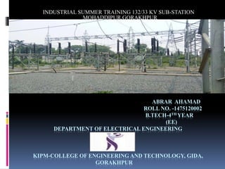
ABRAR AHAMAD
ROLL NO. -1475120002
B.TECH-4TH YEAR
(EE)
DEPARTMENT OF ELECTRICAL ENGINEERING
KIPM-COLLEGE OF ENGINEERING AND TECHNOLOGY, GIDA,
GORAKHPUR
INDUSTRIAL SUMMER TRAINING 132/33 KV SUB-STATION
MOHADDIPUR,GORAKHPUR
TABLE OF CONTENTS
 Introduction
 Single line diagram
 132 KV Sub-Station
 Panel Section
 Yard Section
 Battery Room
 Components of Sub-Station
 Conclusion
 References
INTRODUCTION
Utter Pradesh Power transmission Corporation Limited (UPPTCL) is
The Company responsible for electricity transmission and distribution
within the Indian state of Uttar Pradesh. Its chairman is Shri ALOK
KUMAR. Mr. RAM SURESH is the chief executive engineer of
electricity transmission division-1, UPPTCL Mohaddipur- Gorakhpur.
Basically, MOHADDIPUR Sub-station was established at since 2012.
It sub-station has two division as an old Sub-station division-1,and
other one is new sub-station division-2, which contains of 132/33 kv
power supply . The section-2 of 132/33 kv sub-station was
inaugurated by last Chief Minister of Uttar Pradesh Sri AKHILESH
YADAV.
SINGLE LINE DIAGRAM
The single line diagram of 132/33 kv :-
There areThree sectionof sub-station-
 One incoming section of 132 kv and
 Two outgoing section of 132 kv and 33 kv
1)-132 KV INCOMING SECTION:-
There are Two incoming lines of 132 kv-
• MOTIRAM ADDA
• BARAHUA, MOHADDIPUR
132 /33 KVOUTGOING-
1. 132 KV Outgoing to Railway and
2. 33 kv outgoing to…
 KHORABAR FEEDER
 RAILWAY FEEDER
 TARAMANDAL FEEDER
 UNIVERSITY FEEDER
 DISTT. COURT+HOSPITAL FEEDER
 SAHARA FEEDER
 BUXIPUR
 GDA TOWER
PANELSECTION
 It is a room of various type of panels.
 It has two sections-
• Control Panel Section:-
It contains panels related to controlling of several instruments like-
Feeder Panel, X- mer Panel, etc.
• Relay and Protection Panel Section:-
It contain panel related to relay systems and protection systems like-
Relay Panel , Transmission line protection panel, etc.
YARD SECTION
132 KV SECTION:-
• It work on 132 kv.
• There are Two bus bars in which one is Main bus-bar and other one is
Transfer bus-bar.
• It has Two incoming feeders i.e. from MOTIRAM ADDAAND
BARAHUA MOHADDIPUR
132/33 KV SECTION:-
132 kv Railway (Outgoing) And
33 kv outgoingsection-
• It is work on 33 kv.
• It has Four Outgoing feeders of 33 kv .
• It is transmission of the power supply through the outgoing feeders to
SHAHPUR, BUXIPUR, GDA TOWER…..
• These 33 kv supply is given by three 40 MVA transformers.
• These three transformers converts 132/33 kv.
• These lines is directly injected to many industries and distributers like-
SAHARA FEEDER, RAILWAY FEEDER,KHORABAR FEEDER,
TATARAMANDAL FEEDER and etc.
BATTERY ROOM
 110 dc supply required for operation of circuit breakers-
o 55 batteries of 2 v,300AH (For regular use.
o 55 batteries of 2v, 300AH (For backup).
 DC supply also required for operation in Control Room-
o Batteries of 2v, 500 AH (Exide Industrial)
COMPONENTS OS SUB-STATION-
 REAY
 CIRCUIT BREAKER
 ISOLATER
 TRANSFORMER
• CURRENT TRANSFORMER (CT)
• POTENTIAL TRANSFORMER(PT)
• CAPACITOR VOLTAGE TRANSFORMER (CVT)
 LIGHTENING ARRESTER (LA)
 FEEDER
 BUS-BAR
 INSULATOR
 WAVE TRAP
 CAPACITOR BANK
RELAY
 A relay is an electromagnetic device which detects the fault and is
responsible for energising the trip circuit of a circuit beaker.
 The relay operates when the resultant torque is positive.
CIRCUIT BREAKER
 A circuit breaker is automatically operated electrical switch, it has to
perform major duties under short short circuit conditions-
• It opens the contacts to clear the faults.
• To carry faults current for short duration while another circuit breaker
is clearing the fault.
• To close the contacts on to a fault.
ISOLATER
 It is an off load device.
 It is a switch operated manually, which separate the circuit from the
power main and discharges the trapped charges in the circuit.
TRANSFORMER
Transformer is an static device which operates on the principal of
Faraday’s law of electromagnetic induction. It transfer the electrical
energy in the form of like (voltage or current) from one circuit to
another circuit without change in its frequency but change in voltage.
There are three 40 MVA transformer-
1. Two 40 MVA, 132/33 kv transformer (BBL MAKER) and
2. One 40 MVA, 132/33 kv transformer (AREVA MAKER).
CURRENT TRANSFORMER
It is a step up transformer which is used to measure the current by
stepping up the voltage level.
POTENTIAL TRANSFORMER
It is a step down transformer which is used to measure the voltage level
by stepping up the voltage level.
CAPACITOR VOLTAGE TRANSFORMER
It is used to step down extra high voltage signals and provide a low
voltage signal for voltage measurement.
LIGHTNING ARRESTER
 It divert to very high voltage level line to ground.
 It protect to the insulation and conductors of the system from the
damaging effects of lightning.
FEEDER
 It is a circuit conductor b/w the power supply source and final branch
circuit over current device.
BUS-BAR
 A bus-bar is a thick strip of Copper or Aluminium that conduct
electricity in electrical power distribution system.
 It can be rectangular shape or can be hollow tubes.
CAPACITOR BANK
Capacitor bank is provide extra energy source to the system while the
voltage may get low.
WAVE TRAP
Tripping the high frequency communication signal sent on the line from
the wide sub-station and diverting them to the telecom panel in the sub
station control room.
CONCLUSION
Every engineer want to getting any important task in practically but not
theoretically, and every students supposed to undergo practical training
session after 3rd year where I have widely got the knowledge about
transmission, distribution and maintenance with economical factors
related to it.
At last I would like to say that practical training taken at 132 kv sub
station MOHADDIPUR has widened knowledge and widened my
thinking as a professional.
REFERENCES
 WWW.Slide shere.net
 WWW.Scrbd.com
 WWW.Seminorsonly.com
 WWW.Wikipedia.com

PPT ON SUMMER VOCATIONAL TRAINING ON 132/33 KV AT MOHADDIPUR, SUB-STATION, GORAKHPUR

  • 1.
    ABRAR AHAMAD ROLL NO.-1475120002 B.TECH-4TH YEAR (EE) DEPARTMENT OF ELECTRICAL ENGINEERING KIPM-COLLEGE OF ENGINEERING AND TECHNOLOGY, GIDA, GORAKHPUR INDUSTRIAL SUMMER TRAINING 132/33 KV SUB-STATION MOHADDIPUR,GORAKHPUR
  • 2.
    TABLE OF CONTENTS Introduction  Single line diagram  132 KV Sub-Station  Panel Section  Yard Section  Battery Room  Components of Sub-Station  Conclusion  References
  • 3.
    INTRODUCTION Utter Pradesh Powertransmission Corporation Limited (UPPTCL) is The Company responsible for electricity transmission and distribution within the Indian state of Uttar Pradesh. Its chairman is Shri ALOK KUMAR. Mr. RAM SURESH is the chief executive engineer of electricity transmission division-1, UPPTCL Mohaddipur- Gorakhpur. Basically, MOHADDIPUR Sub-station was established at since 2012. It sub-station has two division as an old Sub-station division-1,and other one is new sub-station division-2, which contains of 132/33 kv power supply . The section-2 of 132/33 kv sub-station was inaugurated by last Chief Minister of Uttar Pradesh Sri AKHILESH YADAV.
  • 4.
    SINGLE LINE DIAGRAM Thesingle line diagram of 132/33 kv :-
  • 5.
    There areThree sectionofsub-station-  One incoming section of 132 kv and  Two outgoing section of 132 kv and 33 kv 1)-132 KV INCOMING SECTION:- There are Two incoming lines of 132 kv- • MOTIRAM ADDA • BARAHUA, MOHADDIPUR
  • 6.
    132 /33 KVOUTGOING- 1.132 KV Outgoing to Railway and 2. 33 kv outgoing to…  KHORABAR FEEDER  RAILWAY FEEDER  TARAMANDAL FEEDER  UNIVERSITY FEEDER  DISTT. COURT+HOSPITAL FEEDER  SAHARA FEEDER  BUXIPUR  GDA TOWER
  • 7.
    PANELSECTION  It isa room of various type of panels.  It has two sections- • Control Panel Section:- It contains panels related to controlling of several instruments like- Feeder Panel, X- mer Panel, etc. • Relay and Protection Panel Section:- It contain panel related to relay systems and protection systems like- Relay Panel , Transmission line protection panel, etc.
  • 8.
    YARD SECTION 132 KVSECTION:- • It work on 132 kv. • There are Two bus bars in which one is Main bus-bar and other one is Transfer bus-bar. • It has Two incoming feeders i.e. from MOTIRAM ADDAAND BARAHUA MOHADDIPUR
  • 9.
    132/33 KV SECTION:- 132kv Railway (Outgoing) And 33 kv outgoingsection- • It is work on 33 kv. • It has Four Outgoing feeders of 33 kv . • It is transmission of the power supply through the outgoing feeders to SHAHPUR, BUXIPUR, GDA TOWER….. • These 33 kv supply is given by three 40 MVA transformers. • These three transformers converts 132/33 kv. • These lines is directly injected to many industries and distributers like- SAHARA FEEDER, RAILWAY FEEDER,KHORABAR FEEDER, TATARAMANDAL FEEDER and etc.
  • 10.
    BATTERY ROOM  110dc supply required for operation of circuit breakers- o 55 batteries of 2 v,300AH (For regular use. o 55 batteries of 2v, 300AH (For backup).  DC supply also required for operation in Control Room- o Batteries of 2v, 500 AH (Exide Industrial)
  • 11.
    COMPONENTS OS SUB-STATION- REAY  CIRCUIT BREAKER  ISOLATER  TRANSFORMER • CURRENT TRANSFORMER (CT) • POTENTIAL TRANSFORMER(PT) • CAPACITOR VOLTAGE TRANSFORMER (CVT)  LIGHTENING ARRESTER (LA)  FEEDER  BUS-BAR  INSULATOR  WAVE TRAP  CAPACITOR BANK
  • 12.
    RELAY  A relayis an electromagnetic device which detects the fault and is responsible for energising the trip circuit of a circuit beaker.  The relay operates when the resultant torque is positive. CIRCUIT BREAKER  A circuit breaker is automatically operated electrical switch, it has to perform major duties under short short circuit conditions- • It opens the contacts to clear the faults. • To carry faults current for short duration while another circuit breaker is clearing the fault. • To close the contacts on to a fault.
  • 13.
    ISOLATER  It isan off load device.  It is a switch operated manually, which separate the circuit from the power main and discharges the trapped charges in the circuit. TRANSFORMER Transformer is an static device which operates on the principal of Faraday’s law of electromagnetic induction. It transfer the electrical energy in the form of like (voltage or current) from one circuit to another circuit without change in its frequency but change in voltage. There are three 40 MVA transformer- 1. Two 40 MVA, 132/33 kv transformer (BBL MAKER) and 2. One 40 MVA, 132/33 kv transformer (AREVA MAKER).
  • 14.
    CURRENT TRANSFORMER It isa step up transformer which is used to measure the current by stepping up the voltage level. POTENTIAL TRANSFORMER It is a step down transformer which is used to measure the voltage level by stepping up the voltage level. CAPACITOR VOLTAGE TRANSFORMER It is used to step down extra high voltage signals and provide a low voltage signal for voltage measurement. LIGHTNING ARRESTER  It divert to very high voltage level line to ground.  It protect to the insulation and conductors of the system from the damaging effects of lightning. FEEDER  It is a circuit conductor b/w the power supply source and final branch circuit over current device.
  • 15.
    BUS-BAR  A bus-baris a thick strip of Copper or Aluminium that conduct electricity in electrical power distribution system.  It can be rectangular shape or can be hollow tubes. CAPACITOR BANK Capacitor bank is provide extra energy source to the system while the voltage may get low. WAVE TRAP Tripping the high frequency communication signal sent on the line from the wide sub-station and diverting them to the telecom panel in the sub station control room.
  • 16.
    CONCLUSION Every engineer wantto getting any important task in practically but not theoretically, and every students supposed to undergo practical training session after 3rd year where I have widely got the knowledge about transmission, distribution and maintenance with economical factors related to it. At last I would like to say that practical training taken at 132 kv sub station MOHADDIPUR has widened knowledge and widened my thinking as a professional.
  • 17.
    REFERENCES  WWW.Slide shere.net WWW.Scrbd.com  WWW.Seminorsonly.com  WWW.Wikipedia.com