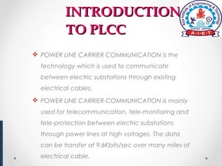
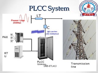
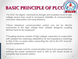
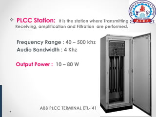
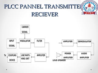
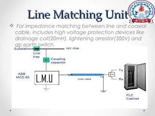
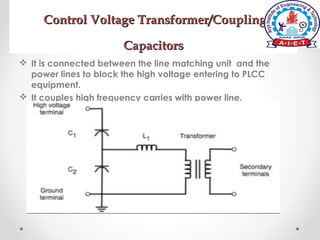
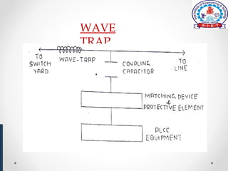
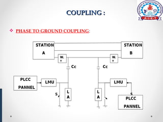
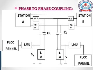
Submitted By:- Submitted To:-
Md Aslam Er. Vidhi Virat
12EAIEC090 Er. Nemichand
(Seminar Coordinator)
INTRODUCTIONINTRODUCTION
TO PLCCTO PLCC
 POWER LINE CARRIER COMMUNICATION is the
technology which is used to communicate
between electric substations through existing
electrical cables.
 POWER LINE CARRIER COMMUNICATION is mainly
used for telecommunication, tele-monitoring and
tele-protection between electric substations
through power lines at high voltages. The data
can be transfer at 9.6Kbits/sec over many miles of
electrical cable.
PLCC SystemPLCC System
BASIC PRINCIPLE OF PLCCBASIC PRINCIPLE OF PLCC
In PLCC the higher mechanical strength and insulation level of high
voltage power lines result in increased reliability of communication
and lower attenuation over long-distance.
Since telephone communication system can not be directly
connected to the high voltage lines, suitably designed coupling
devices have to be employed.
Coupling devices consists of high voltage capacitors in conjunction
with suitable line matching units(LMU’s) for line impedance matching
to that of the co-axial cable connecting the unit to the PLC transmit-
receive equipment.
Carrier currents used for communication have to be prevented from
entering the power equipment used in GSS as this would results in
complete loss of power system.
EQUIPMENTS USEDEQUIPMENTS USED
 PLCC Station.
 Line Matching Unit
(LMU).
 CVT/CC.
 Earth switching.
 Lightning Arrestor.
 Wave Trap.
 Co axial Cable.
 PLCC Station: It is the station where Transmitting,
Receiving, amplification and Filtration are performed.
Frequency Range : 40 – 500 khz
Audio Bandwidth : 4 Khz
Output Power : 10 – 80 W
ABB PLCC TERMINAL ETL- 41
PLCC PANNEL TRANSMITTER/PLCC PANNEL TRANSMITTER/
RECIEVERRECIEVER
Line Matching UnitLine Matching Unit
 For impedance matching between line and coaxial
cable, includes high voltage protection devices like
drainage coil(20mH), lightening arrestor(500V) and
an earth switch.
LMU functional
Control Voltage Transformer/CouplingControl Voltage Transformer/Coupling
CapacitorsCapacitors
 It is connected between the line matching unit and the
power lines to block the high voltage entering to PLCC
equipment.
 It couples high frequency carries with power line.
 Earth Switch: This is used for the maintenances of
LMU. The main function of Earth switch is to ground the
trapped charges.
 Lightning Arrestor: This is used for arresting any
A.C. high voltages spike entering to the LINE MATCHING
UNIT.
 Co- Axial cable: This is used for interconnection
between PLCC Station and LMU for carrying high
frequency signal.
WAVE TRAPS or LINE TRAPS
•Wave traps – (WT’s) are used between the transmission line and
the power stations to avoid carrier power dislocation in the power
plant and cross talk with other power line carrier circuits connected
to the same power station.
•WT’s also ensure proper operating conditions and signal levels at
the PLCC transmit receive equipment irrespective of switching
conditions of the power circuits and equipment in the station.
A wave trap must satisfy the following requirements:
 1)     It must block the carrier currents. By blocking, we mean that
the track should attenuate the H.F. signals by at least 8 to 10 dB.
2)  It must carry the power frequency current safely during normal
operation as well as during short circuit fault conditions.
WAVE
TRAP
COUPLING :COUPLING :
 PHASE TO GROUND COUPLING:
 PHASE TO PHASE COUPLINGPHASE TO PHASE COUPLING::
ADVANTAGESADVANTAGES
• 1. No separate wires are needed for communication purposes, as the power lines
themselves carry power as well as communication signals. Hence the cost is less.
• 2. Power lines have appreciably higher mechanical strength compared with
ordinary lines. They would normally remain unaffected under the conditions,
which might seriously damage telephone lines.
• 3. Power lines usually provide the shortest route between the power stations.
• 4. Power lines have large cross-sectional area resulting in very low resistance
per unit length. Consequently carrier signals suffer much less attenuation than
when they travel on telephone lines of equal lengths.
• 5. Power lines are well insulated to provide only negligible leakage between
conductors and ground even in adverse weather conditions
• 6. Largest spacing between conductors reduces capacitance, which results in
smaller attenuation at high frequencies. The large spacing also reduces the
cross talk to a considerable extent.
DISADVANTAGESDISADVANTAGES
• 1. Proper care has to be taken to guard carrier equipment and persons
using them against high voltages and currents on the lines.
• 2. High voltage lines have transformer connections, attenuate carrier
currents. Sub-station equipments adversely affect the carrier currents.
• 3.  Noise introduced by power lines is far more than in case of telephone
lines. This is due to the noise generated by discharge across insulators,
corona and switching processes.
• 4. The noise is also introduced in the signal due to bad weather
conditions.
THANK YOU
QUERIES…..QUERIES…..

Ppt.aslam

  • 1.
    Submitted By:- SubmittedTo:- Md Aslam Er. Vidhi Virat 12EAIEC090 Er. Nemichand (Seminar Coordinator)
  • 2.
    INTRODUCTIONINTRODUCTION TO PLCCTO PLCC POWER LINE CARRIER COMMUNICATION is the technology which is used to communicate between electric substations through existing electrical cables.  POWER LINE CARRIER COMMUNICATION is mainly used for telecommunication, tele-monitoring and tele-protection between electric substations through power lines at high voltages. The data can be transfer at 9.6Kbits/sec over many miles of electrical cable.
  • 3.
  • 4.
    BASIC PRINCIPLE OFPLCCBASIC PRINCIPLE OF PLCC In PLCC the higher mechanical strength and insulation level of high voltage power lines result in increased reliability of communication and lower attenuation over long-distance. Since telephone communication system can not be directly connected to the high voltage lines, suitably designed coupling devices have to be employed. Coupling devices consists of high voltage capacitors in conjunction with suitable line matching units(LMU’s) for line impedance matching to that of the co-axial cable connecting the unit to the PLC transmit- receive equipment. Carrier currents used for communication have to be prevented from entering the power equipment used in GSS as this would results in complete loss of power system.
  • 5.
    EQUIPMENTS USEDEQUIPMENTS USED PLCC Station.  Line Matching Unit (LMU).  CVT/CC.  Earth switching.  Lightning Arrestor.  Wave Trap.  Co axial Cable.
  • 6.
     PLCC Station:It is the station where Transmitting, Receiving, amplification and Filtration are performed. Frequency Range : 40 – 500 khz Audio Bandwidth : 4 Khz Output Power : 10 – 80 W ABB PLCC TERMINAL ETL- 41
  • 7.
    PLCC PANNEL TRANSMITTER/PLCCPANNEL TRANSMITTER/ RECIEVERRECIEVER
  • 8.
    Line Matching UnitLineMatching Unit  For impedance matching between line and coaxial cable, includes high voltage protection devices like drainage coil(20mH), lightening arrestor(500V) and an earth switch. LMU functional
  • 9.
    Control Voltage Transformer/CouplingControlVoltage Transformer/Coupling CapacitorsCapacitors  It is connected between the line matching unit and the power lines to block the high voltage entering to PLCC equipment.  It couples high frequency carries with power line.
  • 10.
     Earth Switch:This is used for the maintenances of LMU. The main function of Earth switch is to ground the trapped charges.  Lightning Arrestor: This is used for arresting any A.C. high voltages spike entering to the LINE MATCHING UNIT.  Co- Axial cable: This is used for interconnection between PLCC Station and LMU for carrying high frequency signal.
  • 11.
    WAVE TRAPS orLINE TRAPS •Wave traps – (WT’s) are used between the transmission line and the power stations to avoid carrier power dislocation in the power plant and cross talk with other power line carrier circuits connected to the same power station. •WT’s also ensure proper operating conditions and signal levels at the PLCC transmit receive equipment irrespective of switching conditions of the power circuits and equipment in the station. A wave trap must satisfy the following requirements:  1)     It must block the carrier currents. By blocking, we mean that the track should attenuate the H.F. signals by at least 8 to 10 dB. 2)  It must carry the power frequency current safely during normal operation as well as during short circuit fault conditions.
  • 12.
  • 13.
    COUPLING :COUPLING : PHASE TO GROUND COUPLING:
  • 14.
     PHASE TOPHASE COUPLINGPHASE TO PHASE COUPLING::
  • 15.
    ADVANTAGESADVANTAGES • 1. Noseparate wires are needed for communication purposes, as the power lines themselves carry power as well as communication signals. Hence the cost is less. • 2. Power lines have appreciably higher mechanical strength compared with ordinary lines. They would normally remain unaffected under the conditions, which might seriously damage telephone lines. • 3. Power lines usually provide the shortest route between the power stations. • 4. Power lines have large cross-sectional area resulting in very low resistance per unit length. Consequently carrier signals suffer much less attenuation than when they travel on telephone lines of equal lengths. • 5. Power lines are well insulated to provide only negligible leakage between conductors and ground even in adverse weather conditions • 6. Largest spacing between conductors reduces capacitance, which results in smaller attenuation at high frequencies. The large spacing also reduces the cross talk to a considerable extent.
  • 16.
    DISADVANTAGESDISADVANTAGES • 1. Propercare has to be taken to guard carrier equipment and persons using them against high voltages and currents on the lines. • 2. High voltage lines have transformer connections, attenuate carrier currents. Sub-station equipments adversely affect the carrier currents. • 3.  Noise introduced by power lines is far more than in case of telephone lines. This is due to the noise generated by discharge across insulators, corona and switching processes. • 4. The noise is also introduced in the signal due to bad weather conditions.
  • 17.
  • 18.