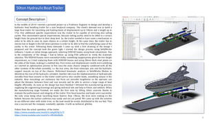
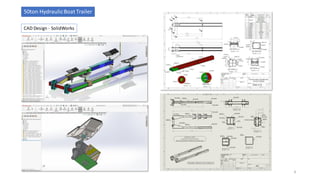
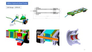
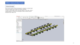
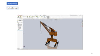
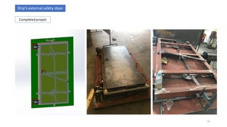
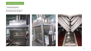
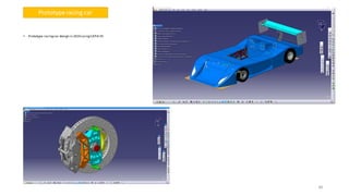
THEODOROS DRAGONAS
Mechanical Design Engineer
PORTFOLIO
Marine Industry
Construction Industry
Special Purpose Machinery
+ Conveyors
Food Processing
Industry
+30-6932980020
theodragonas@gmail.com
https://www.linkedin.com/in/th-dragonas/
Motorsport
Marine Industry
50ton HydraulicBoat Trailer
180ton HydraulicBoat Trailer
200ton HydraulicBoat Trailer
Off-Shore Crane
2
Special Structure for Catamaranyachts
Ship’sexternal safety door
In the middle of 2014 I started a personal project as a Freelance Engineer to design and develop a
hydraulic boat handling trailer for a new boatyard company. The client’s demand was to build a
large boat trailer for launching and hauling boats of displacement up to 50tons and a length up to
17m. One additional specific requirement was the trailer to be capable of servicing also sailing
yachts. This necessitated special requirements, because sailing yachts need to be lifted in a certain
height from the ground due to their deep keel. So, the trailer needed to have some a mechanism in
order to be able to raise its main chassis to a certain height. At the same time, the trailer has to
remain low in height in the full down position in order to be able to find the underlying cause of the
yachts in the water. Following these demands I came up with a first drawing of the design I
proposed and the concept took the green light. I started the design process using SolidWorks
software. I made an initial design approach, selecting HEB340 beams using hand calculations. Due
to the complexity of the design, I had to follow up using FEA software to verify the materials
selection. The HEB340 beams were somewhat bulky, something inappropriate given the low height
requirement, so I tried replacing them with HEB300 beams and using 20mm thick steel plates on
the sides of the beam, making it a welded box. First stress and displacement results were satisfying
so I started an optimization process to fine tune the main chassis integrity combined with all the
other systems of the whole assembly, i.e. the rear arms, the front telescopic arm and the hydraulic
support mounts on top of the chassis. Performed kinematic analysis in SolidWorks Motion to
determine the size of the hydraulic cylinders. Another idea was the implementation of hydraulically
movable front boat mounts so the trailer could service also smaller boats, something unique in the
industry. Rear mountings are stationary but front are movable lengthwise so the operator can
adjust the distance between front and rear mounts and be able to service a large range of boat
lengths efficiently. As soon as the design has been finished I followed the manufacturing process,
supplying the engineering drawings and giving technical info and help to fitters and welders. When
the manufacturing stage finished, we made the first tests by lifting 10ton concrete blocks to
evaluate the performance and integrity of the trailer. First boat launches and hauls were successful;
the only issue being when launching boats heavier than 10tons, the tires were sinking on the
bottom because the surface undersea was sandy and not yet paved. We came up with the solution
to use different axles with wider tires, so the load would be evenly distributed to the sea bed. That
was a success and the company constantly operates it with no technical glitches.
Videos from the actual operation of the trailer:
https://www.youtube.com/watch?v=p4g3O9q7e7Y
https://www.youtube.com/watch?v=48I6h6dhkIk
Concept Description
50ton HydraulicBoat Trailer
3
CAD Design - SolidWorks
50ton HydraulicBoat Trailer
4
F.E.A. Analysis- ANSYS
50ton HydraulicBoat Trailer
5
50ton total Load
• FEA Analysis with a total external load of 50t plus gravity force.
• Load distribution: 10t on each front support, 15t on each rear support
• Front retractable bracket fully extended
• Mesh optimization
• Perfectly acceptable stress figures on the whole chassis, well below material’s
yield point
• Abnormal peak stress on rear support pin, requires further analysis
• Mesh singularity possibility will be checked
• Nonlinear contacts will be applied in the pin-bushing intersection to get more
realistic results
F.E.A. Analysis- ANSYS
50ton HydraulicBoat Trailer
6
60ton total Load
• FEA Analysis with a total external load of 60t plus gravity force.
• Load distribution: 12t on each front support, 18t on each rear support
• Front retractable bracket fully extended
• Mesh optimization
• Perfectly acceptable stress figures on the whole chassis, well below material’s
yield point
• Abnormal peak stress on rear support pin, requires further analysis
• Mesh singularity possibility will be checked
• Nonlinear contacts will be applied in the pin-bushing intersection to get more
realistic results
The nonlinear contact analysis showed that the stress peak was not
realistic. Maximum von-Mises stress was still past the material’s yield
point, so the 60ton load was inappropriate, except of increasing the
diameter of the pin. That was not an option because the percentage of
yachts in the area weighing more than 50tons is very small. A back to
back analysis was performed with a load of 50tons and everything was
back to normal.
F.E.A. Analysis– ANSYSNonlinear
50ton HydraulicBoat Trailer
7
Non-linear Contacts
60ton
Linear Contacts
Non-linear Contacts
50ton60ton – 370MPa
50ton – 269MPa
The last study was a fatigue analysis of the rear support pin, for a total
load of 50tons. Soderberg criteria selected as most appropriate for this
type of material (C45E). Fatigue life was found to be 9.185 cycles.
In the situation where the trailer conducts one haul and 1 launch per day,
then the expected life of the support pin should be 12.5 years which is
perfectly acceptable.
F.E.A. Analysis– ANSYSFatigue
50ton HydraulicBoat Trailer
8
KinematicAnalysis of the trailer height-adjusting mechanism was
critical as the ability of the system to withstand large-scale loads
while being able to remain functional, could then be evaluated.
Furthermore, this analysis was essential to select the hydraulic
cylinders’ characteristics, as well as the hydrauliccircuit working
pressure.The analysis was held on SolidWorks Motions Analysis
add-in and it gave some important results. With the front
hydraulicarm fully retracted,the force applied on the front
chassis supports was 264kN,while with the front arm fully
extended the force was 326kN. That was for a 12-secfull
displacement cycle beginning from the bottom to the top
position. The load exerted on the front supports was 40tons,
quire a safe number given that the total load exerted on both the
front and rear supports would never exceed 50tons.
Another set of analyses were held with no externalloads exerted
on the supports, just the gravity force.
Click on the link below to watch the animation
https://youtu.be/5zN97mq6pUc
KinematicAnalysis
SolidWorks
40ton Load / Front Arm fully retracted /264 kN max. force
40ton Load / Front Arm fully extended/326 kN max. force
Gravity Force / Front Arm fully retracted / 216 kN max. force
Gravity Force / Front Arm fully retracted / 263 kN max. force
50ton HydraulicBoat Trailer
9
10
50ton HydraulicBoat Trailer
10
Completed Project
Structure for CatamaranYachts
Completed Project
YouTube link:
https://youtu.be/h6vu8MzLZf8
11
12
Concept Description
180ton HydraulicBoat Trailer
12
• Concept started in 2010, after a request from a large boatyard of the area.
• The trailer should be very low, with steerable front wheels
• The hydraulic cylinders supporting the boat should be telescopic to reach the
minimum height required
• The chassis should have 4 heavy-duty hydraulic supports on its bottom to rest
on them as long as the boat was placed on its final position at the boatyard.
• We could only use 12 wheels so we had to source some heavy-duty aircraft
tires to withstand the high loads.
• The wheels rims should be bespoke and split.
• The trailer was designed in CATIA V5 and analyzed in ANSYS F.E.A.
• The trailer is still in service today with great success.
CAD Design – CATIA V5
180ton HydraulicBoat Trailer
13
This is a new concept I currently developing for a boatyard in a Greek island.
Totally new design, with an option to be remote controlled.
A series of wheel bogies ensure the high capacity of the trailer, while a
complex hydraulic circuit has to be developed to make it efficient and safe.
Estimated trailer length: 30m
Future Concept
200ton HydraulicBoat Trailer
14
PORT Crane
15
Future Concept
Ship’sexternal safety door
16
Completed project
Construction
Industry
Tower Crane
Excavator
Truck Crane
17
TOWER Crane
18
Future Concept
Excavator
19
Future Concept
Truck Crane
20
Future Concept
Special Purpose
Machinery / Conveyors
LAFARGE Cement Factory Conveyor
VegetablePolishing Machine
Raisin Feeding Machine
Raisin Packaging Machine
Raisin Weighing Machine
Overhead Crane
Recycled MaterialsConveyor
Electric Bin Tipper
21
ALHELLAS - Saw RealignmentMachine
Concept Description
ALHELLAS - Saw RealignmentMachine
22
That was part of a large project of ALHELLAS Aluminum factory.
This specific machine’s purpose is to align the aluminum material prior
being cut at the saw. Fully designed in SolidWorks software.
Concept Description
LAFARGE Cement Factory Conveyor
23
Ferrous Material Conveyor/Weighing System – Lafarge Cement Factory
Took full responsibility for the entire project, including initial on-site
measurements and consultation. The full assembly was designed in
SolidWorks and I supervised the final erection process. Also overcame
issues with tight space available and made sure the system was
functioning perfectly and completed right on time. We received
compliments from the factory’s general manager.
That was a vegetable (carrot) polishing machine for a foreign client. This machine
consisted of a series of rotating brushes mounted on an oscillating carrier. The carrier
was driven by a high gear ratio motor/gearbox and a special mechanism. The idea was
the brushes to rotate and at the same time move in an oscillating fashion in order to
ensure that the vegetables don’t stay at the same place which would cause damage to
them. All this was mounted on a rigid steel frame. Extra care was taken of the aesthetics
too.
VegetablePolishing Machine
24
Concept Description
Dried raisin feeding machine made of stainless steel for a large raisin production factory
in Greece. Detailed analysis of the working process in order to ensure appropriate flow.
Designed using CATIA V5.
Raisin Feeding Machine
25
Concept Description
Raisin Packaging Machine
26
Concept Description
Dried raisin packagingmachinemade of stainless steel for a largeraisin production factory in
Greece. Detailed analysisof the working process in order to ensure appropriateflow.Special
attention to detail in order to ensure that the mechanismdoes not make any damage to the
cardboard boxes.Designed usingCATIA V5.
Weighing machine made of stainless steel for a large raisin production factory in Greece.
Detailed analysis of the working process in order to ensure appropriate flow. Designed using
CATIA V5.
Raisin Weighing Machine
27
Concept Description
Designed a 5ton single girder overhead travelling crane using SolidWorks and ANSYS FEA for
stress analysis and structural optimization. After reviewing the buildings’ drawings, and
respecting the height and width limitations, I designed an overhead crane of 5ton maximum
capacity. The structure was fabricated as a box beam and it required a material selection
optimization to ensure that maximum bending deflection was less than L/600 according to
the relevant standards.
CAD Design - SolidWorks
F.E.A. Analysis- ANSYS
Overhead Crane
28
Recycled materials chain conveyor. Designed in SolidWorks.
Required extra attention due to very tight available space.
Received compliments from the client.
Recycled MaterialsConveyor
29
Concept Description
Electric Bin tipper.
That was designed for a local cooperative factory.
Used SolidWorks software throughout.
The tipper was very efficient. Received compliments from the client.
Electric Bin Tipper
30
Concept Description
Food Processing
Industry
Cherries Fruit Processing Line
Apples Processing Line
31
Raisin Processing Line
Raw Potatoes Processing Machine
32
Responsible for designing a whole new cherries processing and packaging line, including all
conveyor belts, water supply networks etc. in SolidWorks.Tsomlektsoglou Fruits company
has raised its exports sincethen.
Cherries Fruit Processing Line
32
Concept Description
33
Apple processing line for an Indian client.
Used SolidWorks software throughout.
The tipper was very efficient. Received compliments from the client.
Apples Processing Line
33
Concept Description
Special type machine for raw potatoes processing.
That was designed for a local cooperative factory.
Used SolidWorks software throughout.
The tipper was very efficient. Received compliments from the client.
34
Raw Potatoes Processing Machine
Concept Description
35
Raisin processing line for an Greek client.
Used SolidWorks software throughout.
Raisin Processing Line
35
Concept Description
36
Raisin processing line for an Greek client.
Used SolidWorks software throughout.
Raisin Processing Line
36
Concept Description
37
Raisin processing line for an Greek client.
Used SolidWorks software throughout.
Raisin Processing Line
37
Concept Description
38
Raisin processing line for an Greek client.
Used SolidWorks software throughout.
Raisin Processing Line
38
Concept Description
Motorsport
Prototype racing car
39
40
• Prototype racingcar design in 2010 usingCATIA V5
40
Prototype racing car

Portfolio - Theodoros Dragonas - Mechanical Design Engineer

  • 1.
    THEODOROS DRAGONAS Mechanical DesignEngineer PORTFOLIO Marine Industry Construction Industry Special Purpose Machinery + Conveyors Food Processing Industry +30-6932980020 theodragonas@gmail.com https://www.linkedin.com/in/th-dragonas/ Motorsport
  • 2.
    Marine Industry 50ton HydraulicBoatTrailer 180ton HydraulicBoat Trailer 200ton HydraulicBoat Trailer Off-Shore Crane 2 Special Structure for Catamaranyachts Ship’sexternal safety door
  • 3.
    In the middleof 2014 I started a personal project as a Freelance Engineer to design and develop a hydraulic boat handling trailer for a new boatyard company. The client’s demand was to build a large boat trailer for launching and hauling boats of displacement up to 50tons and a length up to 17m. One additional specific requirement was the trailer to be capable of servicing also sailing yachts. This necessitated special requirements, because sailing yachts need to be lifted in a certain height from the ground due to their deep keel. So, the trailer needed to have some a mechanism in order to be able to raise its main chassis to a certain height. At the same time, the trailer has to remain low in height in the full down position in order to be able to find the underlying cause of the yachts in the water. Following these demands I came up with a first drawing of the design I proposed and the concept took the green light. I started the design process using SolidWorks software. I made an initial design approach, selecting HEB340 beams using hand calculations. Due to the complexity of the design, I had to follow up using FEA software to verify the materials selection. The HEB340 beams were somewhat bulky, something inappropriate given the low height requirement, so I tried replacing them with HEB300 beams and using 20mm thick steel plates on the sides of the beam, making it a welded box. First stress and displacement results were satisfying so I started an optimization process to fine tune the main chassis integrity combined with all the other systems of the whole assembly, i.e. the rear arms, the front telescopic arm and the hydraulic support mounts on top of the chassis. Performed kinematic analysis in SolidWorks Motion to determine the size of the hydraulic cylinders. Another idea was the implementation of hydraulically movable front boat mounts so the trailer could service also smaller boats, something unique in the industry. Rear mountings are stationary but front are movable lengthwise so the operator can adjust the distance between front and rear mounts and be able to service a large range of boat lengths efficiently. As soon as the design has been finished I followed the manufacturing process, supplying the engineering drawings and giving technical info and help to fitters and welders. When the manufacturing stage finished, we made the first tests by lifting 10ton concrete blocks to evaluate the performance and integrity of the trailer. First boat launches and hauls were successful; the only issue being when launching boats heavier than 10tons, the tires were sinking on the bottom because the surface undersea was sandy and not yet paved. We came up with the solution to use different axles with wider tires, so the load would be evenly distributed to the sea bed. That was a success and the company constantly operates it with no technical glitches. Videos from the actual operation of the trailer: https://www.youtube.com/watch?v=p4g3O9q7e7Y https://www.youtube.com/watch?v=48I6h6dhkIk Concept Description 50ton HydraulicBoat Trailer 3
  • 4.
    CAD Design -SolidWorks 50ton HydraulicBoat Trailer 4
  • 5.
    F.E.A. Analysis- ANSYS 50tonHydraulicBoat Trailer 5 50ton total Load • FEA Analysis with a total external load of 50t plus gravity force. • Load distribution: 10t on each front support, 15t on each rear support • Front retractable bracket fully extended • Mesh optimization • Perfectly acceptable stress figures on the whole chassis, well below material’s yield point • Abnormal peak stress on rear support pin, requires further analysis • Mesh singularity possibility will be checked • Nonlinear contacts will be applied in the pin-bushing intersection to get more realistic results
  • 6.
    F.E.A. Analysis- ANSYS 50tonHydraulicBoat Trailer 6 60ton total Load • FEA Analysis with a total external load of 60t plus gravity force. • Load distribution: 12t on each front support, 18t on each rear support • Front retractable bracket fully extended • Mesh optimization • Perfectly acceptable stress figures on the whole chassis, well below material’s yield point • Abnormal peak stress on rear support pin, requires further analysis • Mesh singularity possibility will be checked • Nonlinear contacts will be applied in the pin-bushing intersection to get more realistic results
  • 7.
    The nonlinear contactanalysis showed that the stress peak was not realistic. Maximum von-Mises stress was still past the material’s yield point, so the 60ton load was inappropriate, except of increasing the diameter of the pin. That was not an option because the percentage of yachts in the area weighing more than 50tons is very small. A back to back analysis was performed with a load of 50tons and everything was back to normal. F.E.A. Analysis– ANSYSNonlinear 50ton HydraulicBoat Trailer 7 Non-linear Contacts 60ton Linear Contacts Non-linear Contacts 50ton60ton – 370MPa 50ton – 269MPa
  • 8.
    The last studywas a fatigue analysis of the rear support pin, for a total load of 50tons. Soderberg criteria selected as most appropriate for this type of material (C45E). Fatigue life was found to be 9.185 cycles. In the situation where the trailer conducts one haul and 1 launch per day, then the expected life of the support pin should be 12.5 years which is perfectly acceptable. F.E.A. Analysis– ANSYSFatigue 50ton HydraulicBoat Trailer 8
  • 9.
    KinematicAnalysis of thetrailer height-adjusting mechanism was critical as the ability of the system to withstand large-scale loads while being able to remain functional, could then be evaluated. Furthermore, this analysis was essential to select the hydraulic cylinders’ characteristics, as well as the hydrauliccircuit working pressure.The analysis was held on SolidWorks Motions Analysis add-in and it gave some important results. With the front hydraulicarm fully retracted,the force applied on the front chassis supports was 264kN,while with the front arm fully extended the force was 326kN. That was for a 12-secfull displacement cycle beginning from the bottom to the top position. The load exerted on the front supports was 40tons, quire a safe number given that the total load exerted on both the front and rear supports would never exceed 50tons. Another set of analyses were held with no externalloads exerted on the supports, just the gravity force. Click on the link below to watch the animation https://youtu.be/5zN97mq6pUc KinematicAnalysis SolidWorks 40ton Load / Front Arm fully retracted /264 kN max. force 40ton Load / Front Arm fully extended/326 kN max. force Gravity Force / Front Arm fully retracted / 216 kN max. force Gravity Force / Front Arm fully retracted / 263 kN max. force 50ton HydraulicBoat Trailer 9
  • 10.
  • 11.
    Structure for CatamaranYachts CompletedProject YouTube link: https://youtu.be/h6vu8MzLZf8 11
  • 12.
    12 Concept Description 180ton HydraulicBoatTrailer 12 • Concept started in 2010, after a request from a large boatyard of the area. • The trailer should be very low, with steerable front wheels • The hydraulic cylinders supporting the boat should be telescopic to reach the minimum height required • The chassis should have 4 heavy-duty hydraulic supports on its bottom to rest on them as long as the boat was placed on its final position at the boatyard. • We could only use 12 wheels so we had to source some heavy-duty aircraft tires to withstand the high loads. • The wheels rims should be bespoke and split. • The trailer was designed in CATIA V5 and analyzed in ANSYS F.E.A. • The trailer is still in service today with great success.
  • 13.
    CAD Design –CATIA V5 180ton HydraulicBoat Trailer 13
  • 14.
    This is anew concept I currently developing for a boatyard in a Greek island. Totally new design, with an option to be remote controlled. A series of wheel bogies ensure the high capacity of the trailer, while a complex hydraulic circuit has to be developed to make it efficient and safe. Estimated trailer length: 30m Future Concept 200ton HydraulicBoat Trailer 14
  • 15.
  • 16.
  • 17.
  • 18.
  • 19.
  • 20.
  • 21.
    Special Purpose Machinery /Conveyors LAFARGE Cement Factory Conveyor VegetablePolishing Machine Raisin Feeding Machine Raisin Packaging Machine Raisin Weighing Machine Overhead Crane Recycled MaterialsConveyor Electric Bin Tipper 21 ALHELLAS - Saw RealignmentMachine
  • 22.
    Concept Description ALHELLAS -Saw RealignmentMachine 22 That was part of a large project of ALHELLAS Aluminum factory. This specific machine’s purpose is to align the aluminum material prior being cut at the saw. Fully designed in SolidWorks software.
  • 23.
    Concept Description LAFARGE CementFactory Conveyor 23 Ferrous Material Conveyor/Weighing System – Lafarge Cement Factory Took full responsibility for the entire project, including initial on-site measurements and consultation. The full assembly was designed in SolidWorks and I supervised the final erection process. Also overcame issues with tight space available and made sure the system was functioning perfectly and completed right on time. We received compliments from the factory’s general manager.
  • 24.
    That was avegetable (carrot) polishing machine for a foreign client. This machine consisted of a series of rotating brushes mounted on an oscillating carrier. The carrier was driven by a high gear ratio motor/gearbox and a special mechanism. The idea was the brushes to rotate and at the same time move in an oscillating fashion in order to ensure that the vegetables don’t stay at the same place which would cause damage to them. All this was mounted on a rigid steel frame. Extra care was taken of the aesthetics too. VegetablePolishing Machine 24 Concept Description
  • 25.
    Dried raisin feedingmachine made of stainless steel for a large raisin production factory in Greece. Detailed analysis of the working process in order to ensure appropriate flow. Designed using CATIA V5. Raisin Feeding Machine 25 Concept Description
  • 26.
    Raisin Packaging Machine 26 ConceptDescription Dried raisin packagingmachinemade of stainless steel for a largeraisin production factory in Greece. Detailed analysisof the working process in order to ensure appropriateflow.Special attention to detail in order to ensure that the mechanismdoes not make any damage to the cardboard boxes.Designed usingCATIA V5.
  • 27.
    Weighing machine madeof stainless steel for a large raisin production factory in Greece. Detailed analysis of the working process in order to ensure appropriate flow. Designed using CATIA V5. Raisin Weighing Machine 27 Concept Description
  • 28.
    Designed a 5tonsingle girder overhead travelling crane using SolidWorks and ANSYS FEA for stress analysis and structural optimization. After reviewing the buildings’ drawings, and respecting the height and width limitations, I designed an overhead crane of 5ton maximum capacity. The structure was fabricated as a box beam and it required a material selection optimization to ensure that maximum bending deflection was less than L/600 according to the relevant standards. CAD Design - SolidWorks F.E.A. Analysis- ANSYS Overhead Crane 28
  • 29.
    Recycled materials chainconveyor. Designed in SolidWorks. Required extra attention due to very tight available space. Received compliments from the client. Recycled MaterialsConveyor 29 Concept Description
  • 30.
    Electric Bin tipper. Thatwas designed for a local cooperative factory. Used SolidWorks software throughout. The tipper was very efficient. Received compliments from the client. Electric Bin Tipper 30 Concept Description
  • 31.
    Food Processing Industry Cherries FruitProcessing Line Apples Processing Line 31 Raisin Processing Line Raw Potatoes Processing Machine
  • 32.
    32 Responsible for designinga whole new cherries processing and packaging line, including all conveyor belts, water supply networks etc. in SolidWorks.Tsomlektsoglou Fruits company has raised its exports sincethen. Cherries Fruit Processing Line 32 Concept Description
  • 33.
    33 Apple processing linefor an Indian client. Used SolidWorks software throughout. The tipper was very efficient. Received compliments from the client. Apples Processing Line 33 Concept Description
  • 34.
    Special type machinefor raw potatoes processing. That was designed for a local cooperative factory. Used SolidWorks software throughout. The tipper was very efficient. Received compliments from the client. 34 Raw Potatoes Processing Machine Concept Description
  • 35.
    35 Raisin processing linefor an Greek client. Used SolidWorks software throughout. Raisin Processing Line 35 Concept Description
  • 36.
    36 Raisin processing linefor an Greek client. Used SolidWorks software throughout. Raisin Processing Line 36 Concept Description
  • 37.
    37 Raisin processing linefor an Greek client. Used SolidWorks software throughout. Raisin Processing Line 37 Concept Description
  • 38.
    38 Raisin processing linefor an Greek client. Used SolidWorks software throughout. Raisin Processing Line 38 Concept Description
  • 39.
  • 40.
    40 • Prototype racingcardesign in 2010 usingCATIA V5 40 Prototype racing car