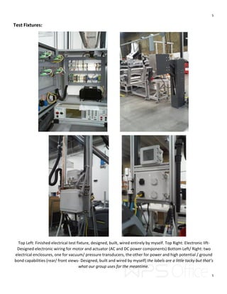
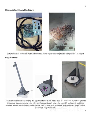
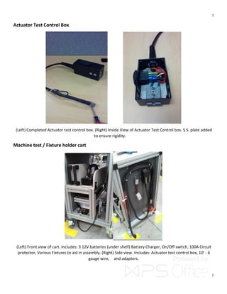
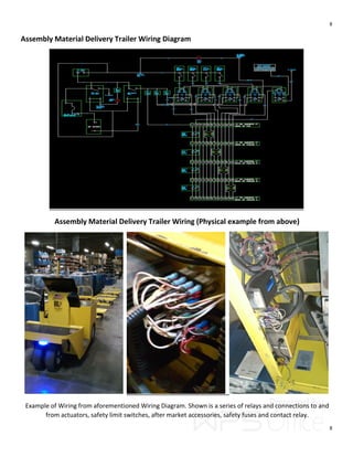
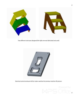
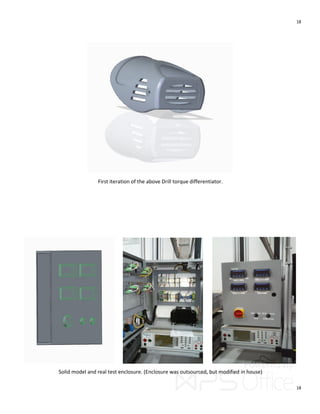
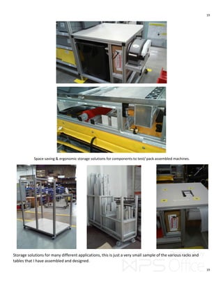
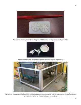
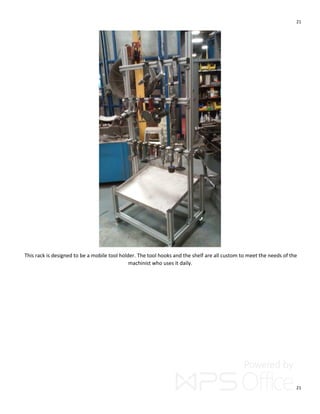
1
1
Engineering Projects from Christopher Haman
3/5/2016
This document contains a compilation of projects reflecting Engineering
achievements from the University of Colorado and Kärcher North
America.
2
2
Table of Contents:
Organic Rankine Cycle - Turbine and turbine housing
Drill torque differentiator
Electronic test fixtures
Electronic Fuel Control Enclosure
Bag Dispenser
Actuator Controls
Machine test / Fixture Cart
Material delivery system electrical project
Zip-tie dispenser rev. B
Sub assembly holder
Zip-tie dispenser rev. A
Miscellaneous small tools
Miscellaneous solid models
Organizational fixtures
3D printed non-circular gears
3D printed band brake system
Safety Fence
Traveling air tool holding rack
3
3
Organic Rankine Cycle: Turbine / Turbine housing
(Left) Complete Organic Rankine Cycle assembled- ready for operation. Success! (Right) LabView graphical results of
voltage produced from Organic Rankine Cycle operation. (Average of around 7-10 watts of power).
(Left) Exploded view of Turbine / Turbine housing components. (Middle) Finished Turbine housing. (Right) Turbine
showing impeller, without electric motor attached.
4
4
Drill torque differentiator
3D printed part and solid model
Drill torque differentiator shown on drill.
This project was to be able to, “differentiate”, like drills with different torque settings in order to keep assemblers from
using the incorrect torque for a given application. (This 3D printed part is colored to denote a specific torque setting and
that will correlate with the work instructions call outs.)
5
5
Test Fixtures:
Top Left: Finished electrical test fixture, designed, built, wired entirely by myself. Top Right: Electronic lift-
Designed electronic wiring for motor and actuator (AC and DC power components) Bottom Left/ Right: two
electrical enclosures, one for vacuum/ pressure transducers, the other for power and high potential / ground
bond capabilities (rear/ front views- Designed, built and wired by myself) the labels are a little tacky but that’s
what our group uses for the meantime.
6
6
Electronic Fuel Control Enclosure
(Left) Completed enclosure. (Right) Intermediate photo of project to emphasize, “complexity” of project.
Bag Dispenser
This assembly allows the user to tip the apparatus forward and slide a large 75+ pound roll of plastic bags onto
the circular base, then capture the roll from the top and easily return the assembly and bag roll upright to
where it is ready and readily accessible for use. (Left / Center) Cad models of, “Bag Dispenser”. (Right) Actual
assembled, “Bag Dispenser”.
7
7
Actuator Test Control Box
(Left) Completed Actuator test control box. (Right) Inside View of Actuator Test Control box. S.S. plate added
to ensure rigidity.
Machine test / Fixture holder cart
(Left) Front view of cart. Includes: 3 12V batteries (under shelf) Battery Charger, On/Off switch, 100A Circuit
protector, Various Fixtures to aid in assembly. (Right) Side view. Includes: Actuator test control box, 10’ - 6
gauge wire, and adapters.
8
8
Assembly Material Delivery Trailer Wiring Diagram
Assembly Material Delivery Trailer Wiring (Physical example from above)
Example of Wiring from aforementioned Wiring Diagram. Shown is a series of relays and connections to and
from actuators, safety limit switches, after market accessories, safety fuses and contact relay.
9
9
Engineering Projects Misc.
This economical and space saving zip-tie holder allows for a two-bin system for lean manufacturing to be employed. It
will soon be a worldwide company standardized fixture. This replaces a simple bin wherein the zip-ties do not fix
properly, fall out and hang into aisles and walkways. Designed and built entirely by myself, It allows the empty, (lower)
tube to be removed and the top tube drops down and rolls forward minimizing assembler time and effort and
maximizing time value added.
10
10
This safety inspired fixture looks over-engineered, although it is designed to hold various different water boxes,
(cream-colored tank) so the assembler can attach fittings and accessories to each one. Because of different sizes of
water boxes, the, “arm” that holds the box moves up and down. A spring is employed for safety, that when the pin is
pulled to move the height, the arm will not fall and cause injuries due to pinch points. The peculiar gray cube is an
accessory for one certain water box to be used in this fixture.
11
11
(Old design that was replaced by above zip-tie fixture)There is supposed to be a gap in between the aluminum
extrusion and the platform. This allows 2 pvc tubes filled with assembly materials to be stored, when one is
used up, it is removed and the second rolls into place where it can be consumed from.
(Left) Cylindrical brush holder. (Middle) Foam roll and PVC tube holder. (Right) Steering shaft holder.
12
12
(Left) Headlight hanging Bracket (Right) Various Hooks – Made using blacksmith techniques.
Simply enough, these are height blocks to hold a machine during testing.
13
13
.
(Left) This apparatus didn’t have the needed capacity originally. Therefore the two legs (wrapped in black
brackets) were cut in half, drilled, flipped 180° and raised to variable heights. Allowing the brackets to support
the entire apparatus to allow for needed capacity. An effective solution in lieu of rendering the apparatus
unusable. (Right) Cad model of brackets used on apparatus. (Cut and bent in metal fabrication dept.)
Shown above are magnetic fixtures for optimal label placement on a painted steel control panel.
14
14
This is a storage rack for holding various sizes of unutilized manufacturing materials.
This is a tool for compressing a fitting in an awkward position, while simultaneously a push nut is loaded into the barrel
and a hammer would hit the smaller barrel fastening the push-nut in place to hold the fitting secure.
(Left) A handmade chain tensioner with finger grips. (Middle) A, “lazy susan”, fixture to hold tall steel panels to attach
gauges etc. (Right) example of middle fixture being used.
15
15
This is a rail where material carts would position themselves to straddle the middle so as to maximize space while
minimizing potential accidents in tight areas.
A simple bracket for mounting a power supply.
Various parts coinciding with previous assemblies.
16
16
Design iterations from previous assemblies.
Various parts coinciding with previous assemblies.
17
17
Two different staircases designed (the right one was fabricated and used)
Electrical control enclosure lid for rocker switches for previous machine lift picture.
18
18
First iteration of the above Drill torque differentiator.
Solid model and real test enclosure. (Enclosure was outsourced, but modified in house)
19
19
Space saving & ergonomic storage solutions for components to test/ pack assembled machines.
Storage solutions for many different applications, this is just a very small sample of the various racks and
tables that I have assembled and designed.
20
20
This is a non-circular gear that was designed and 3D printed while pursuing my Degree At CU.
A band brake that was designed and printed while pursuing my degree at CU
A protective fence around the Roto-Mold 330 to keep objects from interfering with the operation of the platform as well
as maximizing safety for the operators and by-standers.
21
21
This rack is designed to be a mobile tool holder. The tool hooks and the shelf are all custom to meet the needs of the
machinist who uses it daily.

Engineering Projects by Christopher Haman

  • 1.
    1 1 Engineering Projects fromChristopher Haman 3/5/2016 This document contains a compilation of projects reflecting Engineering achievements from the University of Colorado and Kärcher North America.
  • 2.
    2 2 Table of Contents: OrganicRankine Cycle - Turbine and turbine housing Drill torque differentiator Electronic test fixtures Electronic Fuel Control Enclosure Bag Dispenser Actuator Controls Machine test / Fixture Cart Material delivery system electrical project Zip-tie dispenser rev. B Sub assembly holder Zip-tie dispenser rev. A Miscellaneous small tools Miscellaneous solid models Organizational fixtures 3D printed non-circular gears 3D printed band brake system Safety Fence Traveling air tool holding rack
  • 3.
    3 3 Organic Rankine Cycle:Turbine / Turbine housing (Left) Complete Organic Rankine Cycle assembled- ready for operation. Success! (Right) LabView graphical results of voltage produced from Organic Rankine Cycle operation. (Average of around 7-10 watts of power). (Left) Exploded view of Turbine / Turbine housing components. (Middle) Finished Turbine housing. (Right) Turbine showing impeller, without electric motor attached.
  • 4.
    4 4 Drill torque differentiator 3Dprinted part and solid model Drill torque differentiator shown on drill. This project was to be able to, “differentiate”, like drills with different torque settings in order to keep assemblers from using the incorrect torque for a given application. (This 3D printed part is colored to denote a specific torque setting and that will correlate with the work instructions call outs.)
  • 5.
    5 5 Test Fixtures: Top Left:Finished electrical test fixture, designed, built, wired entirely by myself. Top Right: Electronic lift- Designed electronic wiring for motor and actuator (AC and DC power components) Bottom Left/ Right: two electrical enclosures, one for vacuum/ pressure transducers, the other for power and high potential / ground bond capabilities (rear/ front views- Designed, built and wired by myself) the labels are a little tacky but that’s what our group uses for the meantime.
  • 6.
    6 6 Electronic Fuel ControlEnclosure (Left) Completed enclosure. (Right) Intermediate photo of project to emphasize, “complexity” of project. Bag Dispenser This assembly allows the user to tip the apparatus forward and slide a large 75+ pound roll of plastic bags onto the circular base, then capture the roll from the top and easily return the assembly and bag roll upright to where it is ready and readily accessible for use. (Left / Center) Cad models of, “Bag Dispenser”. (Right) Actual assembled, “Bag Dispenser”.
  • 7.
    7 7 Actuator Test ControlBox (Left) Completed Actuator test control box. (Right) Inside View of Actuator Test Control box. S.S. plate added to ensure rigidity. Machine test / Fixture holder cart (Left) Front view of cart. Includes: 3 12V batteries (under shelf) Battery Charger, On/Off switch, 100A Circuit protector, Various Fixtures to aid in assembly. (Right) Side view. Includes: Actuator test control box, 10’ - 6 gauge wire, and adapters.
  • 8.
    8 8 Assembly Material DeliveryTrailer Wiring Diagram Assembly Material Delivery Trailer Wiring (Physical example from above) Example of Wiring from aforementioned Wiring Diagram. Shown is a series of relays and connections to and from actuators, safety limit switches, after market accessories, safety fuses and contact relay.
  • 9.
    9 9 Engineering Projects Misc. Thiseconomical and space saving zip-tie holder allows for a two-bin system for lean manufacturing to be employed. It will soon be a worldwide company standardized fixture. This replaces a simple bin wherein the zip-ties do not fix properly, fall out and hang into aisles and walkways. Designed and built entirely by myself, It allows the empty, (lower) tube to be removed and the top tube drops down and rolls forward minimizing assembler time and effort and maximizing time value added.
  • 10.
    10 10 This safety inspiredfixture looks over-engineered, although it is designed to hold various different water boxes, (cream-colored tank) so the assembler can attach fittings and accessories to each one. Because of different sizes of water boxes, the, “arm” that holds the box moves up and down. A spring is employed for safety, that when the pin is pulled to move the height, the arm will not fall and cause injuries due to pinch points. The peculiar gray cube is an accessory for one certain water box to be used in this fixture.
  • 11.
    11 11 (Old design thatwas replaced by above zip-tie fixture)There is supposed to be a gap in between the aluminum extrusion and the platform. This allows 2 pvc tubes filled with assembly materials to be stored, when one is used up, it is removed and the second rolls into place where it can be consumed from. (Left) Cylindrical brush holder. (Middle) Foam roll and PVC tube holder. (Right) Steering shaft holder.
  • 12.
    12 12 (Left) Headlight hangingBracket (Right) Various Hooks – Made using blacksmith techniques. Simply enough, these are height blocks to hold a machine during testing.
  • 13.
    13 13 . (Left) This apparatusdidn’t have the needed capacity originally. Therefore the two legs (wrapped in black brackets) were cut in half, drilled, flipped 180° and raised to variable heights. Allowing the brackets to support the entire apparatus to allow for needed capacity. An effective solution in lieu of rendering the apparatus unusable. (Right) Cad model of brackets used on apparatus. (Cut and bent in metal fabrication dept.) Shown above are magnetic fixtures for optimal label placement on a painted steel control panel.
  • 14.
    14 14 This is astorage rack for holding various sizes of unutilized manufacturing materials. This is a tool for compressing a fitting in an awkward position, while simultaneously a push nut is loaded into the barrel and a hammer would hit the smaller barrel fastening the push-nut in place to hold the fitting secure. (Left) A handmade chain tensioner with finger grips. (Middle) A, “lazy susan”, fixture to hold tall steel panels to attach gauges etc. (Right) example of middle fixture being used.
  • 15.
    15 15 This is arail where material carts would position themselves to straddle the middle so as to maximize space while minimizing potential accidents in tight areas. A simple bracket for mounting a power supply. Various parts coinciding with previous assemblies.
  • 16.
    16 16 Design iterations fromprevious assemblies. Various parts coinciding with previous assemblies.
  • 17.
    17 17 Two different staircasesdesigned (the right one was fabricated and used) Electrical control enclosure lid for rocker switches for previous machine lift picture.
  • 18.
    18 18 First iteration ofthe above Drill torque differentiator. Solid model and real test enclosure. (Enclosure was outsourced, but modified in house)
  • 19.
    19 19 Space saving &ergonomic storage solutions for components to test/ pack assembled machines. Storage solutions for many different applications, this is just a very small sample of the various racks and tables that I have assembled and designed.
  • 20.
    20 20 This is anon-circular gear that was designed and 3D printed while pursuing my Degree At CU. A band brake that was designed and printed while pursuing my degree at CU A protective fence around the Roto-Mold 330 to keep objects from interfering with the operation of the platform as well as maximizing safety for the operators and by-standers.
  • 21.
    21 21 This rack isdesigned to be a mobile tool holder. The tool hooks and the shelf are all custom to meet the needs of the machinist who uses it daily.