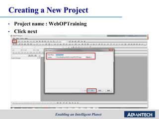
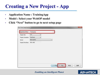
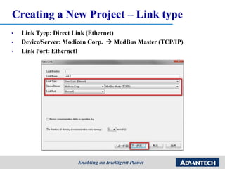
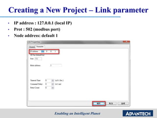
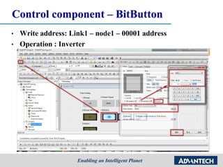
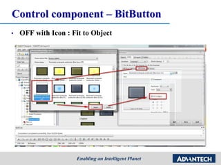
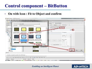
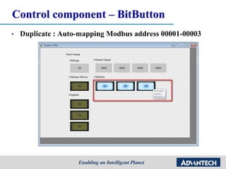
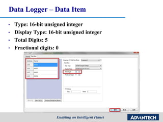
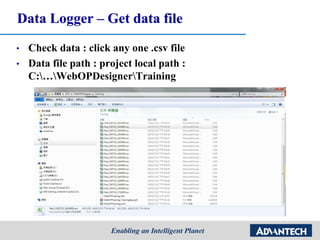
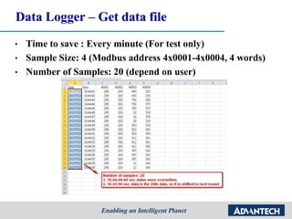
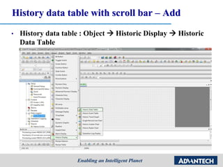
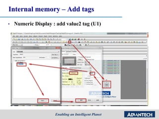
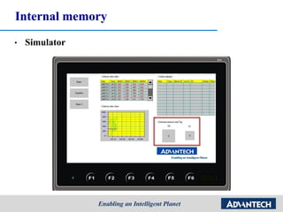
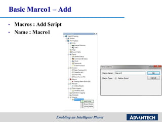
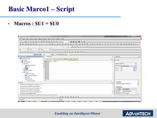
This is tutorial to give you basic concept and how to program HMI Software WebOP Designer / WebAccess-HMI.
•Level 1 : Before Start
•Level 2 : Creating a Project
•Level 3 : Background and Screen Setting
•Level 4 : Data logger and History data display
•Level 5 : Alarm function
•Level 6 : Tag and Internal memory
•Level 7 : Macros
2. C:Program Files
(x86)AdvantechDAQNaviLabviewDriver
Outline
• Level 1 : Before Start
• Level 2 : Creating a Project
• Level 3 : Background and Screen Setting
• Level 4 : Data logger and History data display
• Level 5 : Alarm function
• Level 6 : Tag and Internal memory
• Level 7 : Macros
3. Level 1 : Before Start
1.SW developing environment
2.Video training
3.AE maintenance & trouble shooting
4.Concept and tool
4. Software developing environment
• WebOP designer : 2.1.0.0
• Panel Express : 2.1.0.0
• You can’t open the WebOP project by panel express with
different version.
8. Concept and tool - Development Architecture
• Once user has done the HMI design by WebOP Designer.
• The project could be deployed to WOP Device and
communicate with Controller Device
9. Concept and tool - HMI Mode for WebOP-2000
(BIOS & Panel Setup Mode)
BIOS Mode
1. This mode is for the factory use.
2. The designer can enter this mode to adjust
the initial mode is “RUN AP” or “Panel
Setup” mode.
3. When the HMI power on, press the left-
upper corner and wait for 3~5 seconds.
When you hear the 2nd beep sound, please
release your finger.
Panel Setup Mode
1. This mode is for the designer use.
2. The designer can download their AP
from “Panel Setup” mode.
3. When the HMI power on, press the
right-upper corner and wait for 3~5
seconds. When you hear the 2nd beep
sound, please release your finger.
10. Concept and tool – Date Transfer Helper
• Download Data from WebOP machine
• Flexible to update AP
• Operate type : Logged data, Logged alarms, and recipe data..
• Link setting : Serial, Ethernet, USB
11. Level 2 : Creating a Project to Read/Write
ModBus Address Values
1.Createing a new project and link setup
2.Modbus protocol and utility (Modsim)
3.Display component: BitLamp/Numeric Display
4.Control component: BitButton/Switch/ Numeric Entry
13. Creating a New Project
• Project name : WebOPTraining
• Click next
• Creating a Project Name and selecting the project Location.
14. Creating a New Project - App
• Application Name : TrainingApp
• Model : Select your WebOP model
• Click “Next” button to go to next setup page
15. Creating a New Project – Link type
• Link Tyep: Direct Link (Ethernet)
• Device/Server: Modicon Corp. ModBus Master (TCP/IP)
• Link Port: Ethernet1
16. Creating a New Project – Link parameter
• IP address : 127.0.0.1 (local IP)
• Prot : 502 (modbus port)
• Node address: default 1
18. Creating a New Project – Add text
• Add text Project training Confirm
19. Creating a New Project – Compile
• Compile Online simulation
20. Creating a New Project – Compile
• Compile Online simulation
21. Creating a New Project – Compile
• Run Simulator monitor
22. Creating a Project to Read/Write
ModBus Address Values
1.Createing a new project and link setup
2.Modbus protocol and utility (Modsim)
3.Display component: BitLamp/Numeric Display
4.Control component: BitButton/Switch/ Numeric Entry
23. Modbus protocol and utility
• Modbus table
• Function code
address Point type Coil/Register Numbers Data Addresses Type Table Name
DO 0x 01:coil status 1-9999 0000 to 270E Read-Write Discrete Output Coils
DI 1x 02:input status 10001-19999 0000 to 270E Read-Only Discrete Input Contacts
AI 3x 04:input register 30001-39999 0000 to 270E Read-Only Analog Input Registers
AO 4x 03:holding register 40001-49999 0000 to 270E Read-Write Analog Output Holding Registers
Function Code Action Table Name For address
01 (01 hex) Read Discrete Output Coils 0x
05 (05 hex) Write single Discrete Output Coil 0x
15 (0F hex) Write multiple Discrete Output Coils 0x
02 (02 hex) Read Discrete Input Contacts 1x
04 (04 hex) Read Analog Input Registers 3x
03 (03 hex) Read Analog Output Holding Registers 4x
06 (06 hex) Write single Analog Output Holding Register 4x
16 (10 hex) Write multiple Analog Output Holding Registers 4x
27. Modbus protocol – Modsim32
• ModSim32 : connect to Modbus/TCP server
28. Modbus protocol – Modsim32
• ModSim32 – simulated modbus/TCP server in local PC.
• IP: 127.0.0.1 (default setting)
DO AI
DI AO
29. Creating a Project to Read/Write
ModBus Address Values
1.Createing a new project and link setup
2.Modbus protocol and utility (Modsim)
3.Display component: BitLamp/Numeric Display
4.Control component: BitButton/Switch/ Numeric Entry
30. Display component - BitLamp
• drag and drop a BitLamp object to the Screen 1 for displaying digital tag value
• Monitor address: Link1 – node1 – 00001 address
32. Display component - BitLamp
• BitLamp with Icon : import icon on ON and OFF state
33. Display component - BitLamp
• On with Icon : Fit to Object and confirm
• drag and drop a BitLamp object to the Screen 1 for displaying digital tag value
34. Display component - BitLamp
• OFF with Icon : Fit to Object and confirm
• drag and drop a BitLamp object to the Screen 1 for displaying digital tag value
41. Creating a Project to Read/Write
ModBus Address Values
1.Createing a new project and link setup
2.Modbus protocol and utility (Modsim)
3.Display component: BitLamp/Numeric Display
4.Control component: BitButton/Switch/ Numeric Entry
44. Control component – BitButton
• On with Icon : Fit to Object and confirm
• drag and drop a BitLamp object to the Screen 1 for displaying digital tag value
76. Level 4 : Data logger and History data
display
1.Data logger
2.History data table with scroll bar
3.History trend graph
77. Data Logger – Monitor address
• The data logger will display the value of modbus address
40001-40004 and save data in database
78. Data Logger – Monitor address
• Name: 40001 (depend on user)
• Read Address: 40001 (Monitor and save the address value)
• Sample Size: 4 (Modbus address 4x0001-4x0004, 4 words)
• Number of Samples: 20 (depend on user)
79. Data Logger – Save data to file
• File type : CSV, TXT, and LDF
• Time to save : Every minute (For test only)
• Filename Suffix : _YYMMDD_hhmmss
• Saved path : project local path
80. Data Logger – Data Item
• Type: 16-bit unsigned integer
• Display Type: 16-bit unsigned integer
• Total Digits: 5
• Fractional digits: 0
81. Data Logger – Get data file
• Check data : click any one .csv file
• Data file path : project local path :
C:…WebOPDesignerTraining
82. Data Logger – Get data file
• Time to save : Every minute (For test only)
• Sample Size: 4 (Modbus address 4x0001-4x0004, 4 words)
• Number of Samples: 20 (depend on user)
83. Data logger and History data display
1.Data logger
2.History data table with scroll bar
3.History trend graph
84. History data table with scroll bar – Add
• History data table : Object Historic Display Historic
Data Table
85. History data table with scroll bar – Setting
• Double click history data table to change setting
• Associated Data Logger: Modbus_4X(0)
• Data Source: Data Logger
•
86. History data table with scroll bar – Data Item
• Data Item : show modbus address value 4x0001-4x0004
87. History data table with scroll bar – Add bar
• Type : vertical
• Associated Object ID: HDD0000
88. History data table with scroll bar – Add bar
• Group : link the History data table with scroll bar to a group
• Choose both objects click right button of mouse group
90. Data logger and History data display
1.Data logger
2.History data table with scroll bar
3.History trend graph
91. History trend graph - Add
• History trend graph : Object Historic Display Historic
Trend Graph
92. History trend graph - Add
• Double click history trend graph to change setting
• Associated Data Logger: Modbus_4X(0)
• Data Source: Data Logger
• Number of curves : 4
129. Macro Function
• Global Macro
A global macro is a macro that can be used by all panel applications in the
same project.
• Local Macro
A local macro is a macro that can only be used by the panel application which
the macro is located in.
• Sub-macro
A sub-macro is a macro that can be run by other macros using the CALL
command.
130. Macro Function
• Startup Macro
This macro is run only once when the application starts. The HMI will not display the start-up screen until the
macro terminates. You can use Startup Macro to initialize global data and settings for your application. Specify
Startup Macro in Panel General Setup dialog box.
• Main Macro
This macro is run all the time while the application is running. The HMI runs Main Macro cyclically, i.e. it will
delay preset time to run Main Macro starting from the first command again each time after it completes the
processing of the last command of the macro or when it encounters an END command in the middle of the
macro. Specify Main Macro in Panel General Setup dialog box.
• Event Macro
This Macro is run whenever the associated trigger bit changes from 0 (off) to 1 (on). An application can have
up to four Event Macros which are numbered from 1 to 4. Specify Event Macros in the Panel General Setup
dialog box.
• Time Macro
This Macro is run periodically with a preset time interval. An application can have up to four Time Macros
which are numbered from 1 to 4. Each Time Macro has a different set of time interval options you can choose
to specify how often you want the macro to run. Specify Time Macros in the Panel General Setup dialog box.