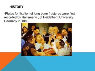
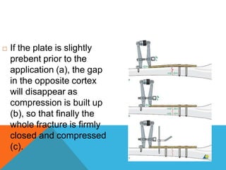
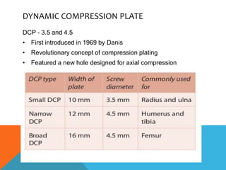
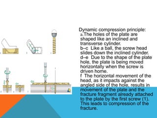
PLATES IN ORTHOPAEDICS
By Dr. Sunil Mann
AO PRINCIPLES
• In 1958, the AO formulated four basic
principles which have become guideline for
internal fixation
– Anatomical reduction
– Stable fixation
– Preservation of blood supply
– Early active mobilization
INDEX
HISTORY
INTRODUCTION
CLASSIFICATION
MODES-NEUTRALIZATION,BUTTRESS,BRIDGING,CONDYLAR
COMPRESSION MODE
COMPRESSION- TENSIONING DEVICE, OVERBANDING
DCP
LCDCP
TUBULAR PLATES
RECON PLATES
ANGLED PLATES
REGIONAL PLATES
STRESS AND STRAIN
HISTORY
-Plates for fixation of long bone fractures were first
recorded by Hansmann , of Heidelberg University,
Germany in 1886.
HISTORY
 Hansmann’s plates were:
 Bent at the end to protrude through the
skin
 Attached to bone by screw with long
shanks
that projected outside the soft tissues.
HISTORY
1912
Shermann plates
HISTORY
1949
ROBERT DANIS
Sodure autogene (autogenous welding)
COAPTEUR
HISTORY
Since 1958, AO has devised a
family of plates for long bone
fractures, starting with a round
holed plate.
In 1969 the Dynamic
Compression Plate was
developed.
In 1994 LC DCP was created.
In 2011 LCP with combination
holes has come into use.
PLATES: INTRODUCTION
• Like an internal splints holding together the fractured end of a
bone
• A load sharing device
• General principle – anatomical reduction and stable internal
fixation
• Two mechanical functions-:
– Transmits force from one end to another bypassing fracture
area
– Holds the fracture ends while maintaining alignment of the
fragments
CLASSIFICATION
• Shape of the plate (semitubular plate)
• Width of the plate (broad/Narrow)
• Shape of the screw hole (Round hole plate)
• Surface contact characteristics of the plate
(low contact)
• Intended site of application
(Clavicle,acetabular,olecranon,DER)
ACC TO FUNCTION
– Neutralization plate
– Buttress plate
_ Bridging plate
– Condylar plate
_ Tension plate
– Compression plate
NEUTRALIZATION PLATE
• Transmits force from one end to
another bypassing the fracture site
• Function – mechanical link
between healthy segment of bone
above and below fracture
• Does not produce compression
• Used In combination with lag screw
• Clinical application
– To protect the screw fixation of a short oblique
fracture
– Butterfly fragment
– Mildly comminuted fracture of long bone
– Fixation of segmental bone defect in combination
with bone graft
. Both DCP and LCP can be used to achieve this mode
it is crucial to use a plate that is long
enough so that at least three bicortical
screw can be inserted in to each main
fragment.
BUTTRESS PLATE
• Applies a force to the bone which is perpendicular to the flat surface
of the plate
• Main function:
– Buttress weakened area of cortex
– Protects from collapsing during healing process
– Designed with large surface area to facilitate wider distribution of load
– Used to maintain bone length or support the depressed fracture
fragment
• Commonly used in fixing
epiphyseal and metaphyseal
Fracture
-T,L or hockey shaped plates are used
-Plate force is perpendicular to the offset of bone
-The first screw lies closest to the fracture site on
shaft hence it will firmly anchors the main
Fragment of plate to the bone
BUTTRESS
k
BRIDGING PLATE
• Called bridge because its fixation is out of the
main zone of injury at the end of the plate to
avoid additional injury in comminuted zone
• Intended to maintain length and alignment of
severly comminuted and segmental fracture
• Limits devitalization of fragments and thereby
allows for a better healing environment
- DCP and LCP are used .
- Plate length should be at-least 3 times the length of the fracture
- It provides relative stability and Indirect(secondary) bone healing occurs with
callus formation
CONDYLAR PLATE
• Has distinct mechanical function
– Maintains the reduction of main intra-articular fragments
– Rigidly fixes the metaphyseal components to diaphyseal shaft,
permitting early movement of the extremity
• Functions as neutralization plate as well as buttress plate. it does act
as compression plate as well.
• Fixed angle of the plate overcomes the coronal plane instability and
prevents consequent collapse.
TENSION PLATING
e
- Frederic Pauwels observed that a
curved, tubular structure under axial load
always has a compression side as well
as a tension side.
- -Under vertical pressure the curved
femur creates a tension force laterally
and a compression force medially
- -A plate positioned on the side of tensile
forces neutralizes them at the fracture
site provided there is cortical contact
opposite to this plate.
- - In case of a cortical defect, the plate will
undergo bending stresses and eventually
fail due to fatigue.
COMPRESSION PLATE
Produce locking force across fracture site
• Works as per Newton’s third law
• Direction of compression is parallel to plate
• General principle
A plate is attached to a bone fragment, pulled across the
fracture site and tension is produced, as a reaction to
this tension, compression is produced at the fracture
site.
-It produces compression across fracture site. If the
fracture is reduced anatomically; plate partially shares
the load until fracture heals finally fracture united
- DCP and LCDCP are used for this mode
COMPRESSION
• Compression may be static or dynamic compression
– Dynamic
• A phenomenon by which a plate can transfer or modify
functional physiological force into compression force at
fracture site
– Static
• A plate applied under tension produces static
compression site, this compression exist constantly even
when limb is at rest or functioning
METHODS OF ACHIEVING COMPRESSION
 With tension devise
 By overbanding
 With dynamic compression principle (DCP/LC-
DCP)
 By contouring plate
 Additional lag screw through plate
COMPRESSION WITH EXTERNAL
DEVISE
 it is recommended for fractures of the femur or humeral
shaft, when the gap to be closed exceeds 1–2 mm, as
well as for the compression of osteotomies and
nonunions.
 After fixation of the plate to one main fragment, the
fracture is reduced and held position with a reduction
forceps. The tension device is now connected to the
plate and fixed to the bone by a short cortex screw.and
then after comression another fragment is fixed to
plate.
Application of the articulated
tension device
 In oblique fractures the
tension device must be
applied in such a way
that the loose fragment
locks in the axilla if
compression is
produced.
 This figure
demonstrates the
tension device applied
in the wrong position
COMPRESSION WITH OVERBANDING
 If a straight plate is
tensioned on a straight
bone, a transverse
fracture gap will open
up due to the eccentric
forces acting on the
opposite side.
 If the plate is slightly
prebent prior to the
application (a), the gap
in the opposite cortex
will disappear as
compression is built up
(b), so that finally the
whole fracture is firmly
closed and compressed
(c).
DYNAMIC COMPRESSION PLATE
DCP - 3.5 and 4.5
• First introduced in 1969 by Danis
• Revolutionary concept of compression plating
• Featured a new hole designed for axial compression
DYNAMIC COMPRESSION PLATE
• Two basic advantages :
– independent axial compression
– the ability to place screws at different angles of inclination.
• Plate application :
Dynamic compression principle:
a.The holes of the plate are
shaped like an inclined and
transverse cylinder.
b–c Like a ball, the screw head
slides down the inclined cylinder.
d–e Due to the shape of the plate
hole, the plate is being moved
horizontally when the screw is
driven home.
f The horizontal movement of the
head, as it impacts against the
angled side of the hole, results in
movement of the plate and the
fracture fragment already attached
to the plate by the first screw (1).
This leads to compression of the
fracture.
 After insertion of one compressing screw, it is only
possible to insert one further screw with compressing
function in the same fragment. Movement of the plate
pushes the first compression screw against the side of
the screw hole and prevents further movement. When
the second screw is tightened, the first has to be
loosened to allow the plate to slide on the bone, after
which it is retightened.
 Screw holes
allow 1mm
compression
 Additional
compression with 1
more eccentric
screw before locking
first screw
The oval shape of the
holes allows 25°
inclination of the screws
in the longitudinal plane,
and up to 7° inclination in
the transversal plane
• The plate can act any of the following depending on the insertion of the
screw
– neutralization
– compression
– buttressing,
• The DC plate can be modified for use and its use is based on fracture
pattern and location
• Certain shortcomings of the DC plate have been discovered through the
years.
– interference with the periosteal blood supply
• plate-induced osteoporosis
• sequestrum could form underneath the plate.
– a soft spot in fracture healing can occur
• possibility of re-fracture
LIMITED CONTACT DYNAMIC COMPRESSION
• Modification that attempts to correct some of the design shortcomings of the DC
plate.
• Based on work by Klaue and Perren, there are three main differences in design.
– sides of the plate are inclined to form a trapezoidal cross section interrupted by
undercuts that form.
• reduces the area of contact between the plate and the periosteal surface of the
bone,
– the screw hole is made up of two inclined and one horizontal cylinder
• they meet at the same angle, permitting compression in both directions
– stress is more equally distributed
• less deformation occurs at the screw holes when contouring
• The biomechanical uses and applications of the LCDC plate are the same as those
for the DC plate.
SEMI-TUBULAR, ONE-THIRD TUBULAR, AND
QUARTERTUBULAR
PLATES
• the first AO self-compression plate designed in the shape of a half tube.
• It provides compression through eccentrically placed oval plate holes.
• Semi tubular plate:
– maintains its rotational stability with edges that dig into the side of the periosteum
under tension.
– Its main indication is for tension resistance
• The one-third tubular plate
– commonly used as a neutralization plate in the treatment of lateral malleolar
fractures.
• The quarter-tubular plates
– have been used in small bone fixation (e.g., in hand surgery).
PLATES
RECONSTRUCTION PLATE
• Designed with notches in its
side so that it can be contoured
in any plane
• Mainly used in fractures of the
pelvis, where precise
contouring is important
• Also be used for fixation of
distal humerus and calcaneal
fractures.
• Relatively low strength, further
diminished with contouring.
• Offers some compression
because of its oval screw holes.
ANGLED PLATES
• Developed in the 1950s for the fixation of proximal and distal femur
fractures.
• They are a one-piece design with a U-shape
profile for the blade portion and a 95° or 130° fixed angle between
the blade and the plate.
• The shaft is thicker than the blade and can withstand higher stress.
• The forces applied in this area exceed 1200 lb/in. with the medial cortex
exposed to compression combined with greater stress and the lateral
cortex exposed to tension.
• The 130° Blade Plate
– originally designed for fixation of proximal femur fractures
– has different lengths to accommodate different fracture
patterns.
– The 4- and 6-hole plates are used for fixation of
intertrochanteric fractures, while the 9- to 12-hole plates are
used for treatment of subtrochanteric fractures.
– It has been replaced for the most part by the dynamic hip
screw, which allows for compression of the fragments.
• The 95° Condylar Blade Plate
– designed for use with supracondylar and bicondylar distal femur
fractures
– the length employed is also fracture specific
– It can be used for sub-trochanteric fractures where more purchase on
the fracture fragment can be gained with a sharper angled plate.
– the device is strong and provides stable fixation
– The need for precise alignment in all three planes demands careful
preoperative planning and intraoperative radiographic control.
REGIONAL PLATES
.
DISTAL HUMERUS PLATES
2 types of plating for fracture intercondylar humerus:
1. Orthogonal plating: if medial plate is kept over the medial
supra condylar ridge and lateral plate is placed over
posterior aspect of lateral column; here both screw
direction are perpendicular to each other ; arrangement is
called orthogonal plating
2. 2. Parallel plating: here plates are kept over both medial
and lateral supracondylar ridges and both screws
direction are parallel to each other; arrangement is called
parallel plating.
STRESS AND STRAIN IN RELATION TO BONE
AND IMPLANT
STRESS RISER
-Stress is an internal force which resist deformation
-At a point where this stress is reasonably higher those points are called
Stress Risers
-Ex- angulation of bone , holes in plates , grooves, bone screw interface,
end of plates
-These stresses weakens the bone part and may lead to fracture e.g.
fracture near callus, fracture at the end of plates etc.
STRESS SHIELDING
-When a implant is loaded specially with wt bearing implant,
it produces osteopenia of bone just beneath the implant.
-This effect is called stress shielding
-This occurs because- when static forces at bone implant
interface is lesser than loading forces , it leads to micro
motion at bone implant interface and finally osteopenia
of underlying bone
PERREN STRAIN THEORY
When the fractured bone is immobilized, the relative movement of
two fragments depends upon
-Stiffness of implant
-Magnitude of external loading
-Stiffness of bridging calluses
Capacity to tolerate the deformation of calluses at fracture site
varies acco to nature of healing at fracture site, this deformation or
strain is expressed in percentage
-strain – 2% ; healing by primary intention
-strain 2-10%; healing by secondary intention
-Strain 10-30% ; threshold level for healing
- Strain > 30% ; bone resorption and non union
THANK YOU

Plates in orthopaedics.pptx

  • 1.
  • 2.
    AO PRINCIPLES • In1958, the AO formulated four basic principles which have become guideline for internal fixation – Anatomical reduction – Stable fixation – Preservation of blood supply – Early active mobilization
  • 3.
    INDEX HISTORY INTRODUCTION CLASSIFICATION MODES-NEUTRALIZATION,BUTTRESS,BRIDGING,CONDYLAR COMPRESSION MODE COMPRESSION- TENSIONINGDEVICE, OVERBANDING DCP LCDCP TUBULAR PLATES RECON PLATES ANGLED PLATES REGIONAL PLATES STRESS AND STRAIN
  • 4.
    HISTORY -Plates for fixationof long bone fractures were first recorded by Hansmann , of Heidelberg University, Germany in 1886.
  • 5.
    HISTORY  Hansmann’s plateswere:  Bent at the end to protrude through the skin  Attached to bone by screw with long shanks that projected outside the soft tissues.
  • 6.
  • 7.
    HISTORY 1949 ROBERT DANIS Sodure autogene(autogenous welding) COAPTEUR
  • 8.
    HISTORY Since 1958, AOhas devised a family of plates for long bone fractures, starting with a round holed plate. In 1969 the Dynamic Compression Plate was developed. In 1994 LC DCP was created. In 2011 LCP with combination holes has come into use.
  • 9.
    PLATES: INTRODUCTION • Likean internal splints holding together the fractured end of a bone • A load sharing device • General principle – anatomical reduction and stable internal fixation • Two mechanical functions-: – Transmits force from one end to another bypassing fracture area – Holds the fracture ends while maintaining alignment of the fragments
  • 10.
    CLASSIFICATION • Shape ofthe plate (semitubular plate) • Width of the plate (broad/Narrow) • Shape of the screw hole (Round hole plate) • Surface contact characteristics of the plate (low contact) • Intended site of application (Clavicle,acetabular,olecranon,DER)
  • 11.
    ACC TO FUNCTION –Neutralization plate – Buttress plate _ Bridging plate – Condylar plate _ Tension plate – Compression plate
  • 12.
    NEUTRALIZATION PLATE • Transmitsforce from one end to another bypassing the fracture site • Function – mechanical link between healthy segment of bone above and below fracture • Does not produce compression • Used In combination with lag screw
  • 13.
    • Clinical application –To protect the screw fixation of a short oblique fracture – Butterfly fragment – Mildly comminuted fracture of long bone – Fixation of segmental bone defect in combination with bone graft . Both DCP and LCP can be used to achieve this mode
  • 14.
    it is crucialto use a plate that is long enough so that at least three bicortical screw can be inserted in to each main fragment.
  • 16.
    BUTTRESS PLATE • Appliesa force to the bone which is perpendicular to the flat surface of the plate • Main function: – Buttress weakened area of cortex – Protects from collapsing during healing process – Designed with large surface area to facilitate wider distribution of load – Used to maintain bone length or support the depressed fracture fragment • Commonly used in fixing epiphyseal and metaphyseal Fracture
  • 17.
    -T,L or hockeyshaped plates are used -Plate force is perpendicular to the offset of bone -The first screw lies closest to the fracture site on shaft hence it will firmly anchors the main Fragment of plate to the bone
  • 18.
  • 19.
    BRIDGING PLATE • Calledbridge because its fixation is out of the main zone of injury at the end of the plate to avoid additional injury in comminuted zone • Intended to maintain length and alignment of severly comminuted and segmental fracture • Limits devitalization of fragments and thereby allows for a better healing environment - DCP and LCP are used . - Plate length should be at-least 3 times the length of the fracture - It provides relative stability and Indirect(secondary) bone healing occurs with callus formation
  • 21.
    CONDYLAR PLATE • Hasdistinct mechanical function – Maintains the reduction of main intra-articular fragments – Rigidly fixes the metaphyseal components to diaphyseal shaft, permitting early movement of the extremity • Functions as neutralization plate as well as buttress plate. it does act as compression plate as well. • Fixed angle of the plate overcomes the coronal plane instability and prevents consequent collapse.
  • 22.
    TENSION PLATING e - FredericPauwels observed that a curved, tubular structure under axial load always has a compression side as well as a tension side. - -Under vertical pressure the curved femur creates a tension force laterally and a compression force medially - -A plate positioned on the side of tensile forces neutralizes them at the fracture site provided there is cortical contact opposite to this plate. - - In case of a cortical defect, the plate will undergo bending stresses and eventually fail due to fatigue.
  • 23.
    COMPRESSION PLATE Produce lockingforce across fracture site • Works as per Newton’s third law • Direction of compression is parallel to plate • General principle A plate is attached to a bone fragment, pulled across the fracture site and tension is produced, as a reaction to this tension, compression is produced at the fracture site. -It produces compression across fracture site. If the fracture is reduced anatomically; plate partially shares the load until fracture heals finally fracture united - DCP and LCDCP are used for this mode
  • 24.
    COMPRESSION • Compression maybe static or dynamic compression – Dynamic • A phenomenon by which a plate can transfer or modify functional physiological force into compression force at fracture site – Static • A plate applied under tension produces static compression site, this compression exist constantly even when limb is at rest or functioning
  • 25.
    METHODS OF ACHIEVINGCOMPRESSION  With tension devise  By overbanding  With dynamic compression principle (DCP/LC- DCP)  By contouring plate  Additional lag screw through plate
  • 26.
    COMPRESSION WITH EXTERNAL DEVISE it is recommended for fractures of the femur or humeral shaft, when the gap to be closed exceeds 1–2 mm, as well as for the compression of osteotomies and nonunions.  After fixation of the plate to one main fragment, the fracture is reduced and held position with a reduction forceps. The tension device is now connected to the plate and fixed to the bone by a short cortex screw.and then after comression another fragment is fixed to plate.
  • 27.
    Application of thearticulated tension device  In oblique fractures the tension device must be applied in such a way that the loose fragment locks in the axilla if compression is produced.  This figure demonstrates the tension device applied in the wrong position
  • 28.
    COMPRESSION WITH OVERBANDING If a straight plate is tensioned on a straight bone, a transverse fracture gap will open up due to the eccentric forces acting on the opposite side.
  • 29.
     If theplate is slightly prebent prior to the application (a), the gap in the opposite cortex will disappear as compression is built up (b), so that finally the whole fracture is firmly closed and compressed (c).
  • 30.
    DYNAMIC COMPRESSION PLATE DCP- 3.5 and 4.5 • First introduced in 1969 by Danis • Revolutionary concept of compression plating • Featured a new hole designed for axial compression
  • 31.
    DYNAMIC COMPRESSION PLATE •Two basic advantages : – independent axial compression – the ability to place screws at different angles of inclination. • Plate application :
  • 32.
    Dynamic compression principle: a.Theholes of the plate are shaped like an inclined and transverse cylinder. b–c Like a ball, the screw head slides down the inclined cylinder. d–e Due to the shape of the plate hole, the plate is being moved horizontally when the screw is driven home. f The horizontal movement of the head, as it impacts against the angled side of the hole, results in movement of the plate and the fracture fragment already attached to the plate by the first screw (1). This leads to compression of the fracture.
  • 33.
     After insertionof one compressing screw, it is only possible to insert one further screw with compressing function in the same fragment. Movement of the plate pushes the first compression screw against the side of the screw hole and prevents further movement. When the second screw is tightened, the first has to be loosened to allow the plate to slide on the bone, after which it is retightened.
  • 34.
     Screw holes allow1mm compression  Additional compression with 1 more eccentric screw before locking first screw
  • 35.
    The oval shapeof the holes allows 25° inclination of the screws in the longitudinal plane, and up to 7° inclination in the transversal plane
  • 36.
    • The platecan act any of the following depending on the insertion of the screw – neutralization – compression – buttressing, • The DC plate can be modified for use and its use is based on fracture pattern and location • Certain shortcomings of the DC plate have been discovered through the years. – interference with the periosteal blood supply • plate-induced osteoporosis • sequestrum could form underneath the plate. – a soft spot in fracture healing can occur • possibility of re-fracture
  • 37.
    LIMITED CONTACT DYNAMICCOMPRESSION • Modification that attempts to correct some of the design shortcomings of the DC plate. • Based on work by Klaue and Perren, there are three main differences in design. – sides of the plate are inclined to form a trapezoidal cross section interrupted by undercuts that form. • reduces the area of contact between the plate and the periosteal surface of the bone, – the screw hole is made up of two inclined and one horizontal cylinder • they meet at the same angle, permitting compression in both directions – stress is more equally distributed • less deformation occurs at the screw holes when contouring • The biomechanical uses and applications of the LCDC plate are the same as those for the DC plate.
  • 40.
    SEMI-TUBULAR, ONE-THIRD TUBULAR,AND QUARTERTUBULAR PLATES • the first AO self-compression plate designed in the shape of a half tube. • It provides compression through eccentrically placed oval plate holes. • Semi tubular plate: – maintains its rotational stability with edges that dig into the side of the periosteum under tension. – Its main indication is for tension resistance • The one-third tubular plate – commonly used as a neutralization plate in the treatment of lateral malleolar fractures. • The quarter-tubular plates – have been used in small bone fixation (e.g., in hand surgery).
  • 41.
  • 42.
    RECONSTRUCTION PLATE • Designedwith notches in its side so that it can be contoured in any plane • Mainly used in fractures of the pelvis, where precise contouring is important • Also be used for fixation of distal humerus and calcaneal fractures. • Relatively low strength, further diminished with contouring. • Offers some compression because of its oval screw holes.
  • 44.
    ANGLED PLATES • Developedin the 1950s for the fixation of proximal and distal femur fractures. • They are a one-piece design with a U-shape profile for the blade portion and a 95° or 130° fixed angle between the blade and the plate. • The shaft is thicker than the blade and can withstand higher stress. • The forces applied in this area exceed 1200 lb/in. with the medial cortex exposed to compression combined with greater stress and the lateral cortex exposed to tension.
  • 45.
    • The 130°Blade Plate – originally designed for fixation of proximal femur fractures – has different lengths to accommodate different fracture patterns. – The 4- and 6-hole plates are used for fixation of intertrochanteric fractures, while the 9- to 12-hole plates are used for treatment of subtrochanteric fractures. – It has been replaced for the most part by the dynamic hip screw, which allows for compression of the fragments.
  • 46.
    • The 95°Condylar Blade Plate – designed for use with supracondylar and bicondylar distal femur fractures – the length employed is also fracture specific – It can be used for sub-trochanteric fractures where more purchase on the fracture fragment can be gained with a sharper angled plate. – the device is strong and provides stable fixation – The need for precise alignment in all three planes demands careful preoperative planning and intraoperative radiographic control.
  • 47.
  • 48.
    DISTAL HUMERUS PLATES 2types of plating for fracture intercondylar humerus: 1. Orthogonal plating: if medial plate is kept over the medial supra condylar ridge and lateral plate is placed over posterior aspect of lateral column; here both screw direction are perpendicular to each other ; arrangement is called orthogonal plating 2. 2. Parallel plating: here plates are kept over both medial and lateral supracondylar ridges and both screws direction are parallel to each other; arrangement is called parallel plating.
  • 49.
    STRESS AND STRAININ RELATION TO BONE AND IMPLANT STRESS RISER -Stress is an internal force which resist deformation -At a point where this stress is reasonably higher those points are called Stress Risers -Ex- angulation of bone , holes in plates , grooves, bone screw interface, end of plates -These stresses weakens the bone part and may lead to fracture e.g. fracture near callus, fracture at the end of plates etc.
  • 50.
    STRESS SHIELDING -When aimplant is loaded specially with wt bearing implant, it produces osteopenia of bone just beneath the implant. -This effect is called stress shielding -This occurs because- when static forces at bone implant interface is lesser than loading forces , it leads to micro motion at bone implant interface and finally osteopenia of underlying bone
  • 51.
    PERREN STRAIN THEORY Whenthe fractured bone is immobilized, the relative movement of two fragments depends upon -Stiffness of implant -Magnitude of external loading -Stiffness of bridging calluses Capacity to tolerate the deformation of calluses at fracture site varies acco to nature of healing at fracture site, this deformation or strain is expressed in percentage -strain – 2% ; healing by primary intention -strain 2-10%; healing by secondary intention -Strain 10-30% ; threshold level for healing - Strain > 30% ; bone resorption and non union
  • 52.