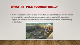
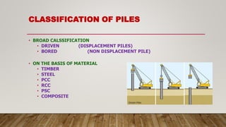
SlideShare a Scribd company logo
PILE FOUNDATION
TYPES OF FOUNDATION
1) Shallow Foundation
Eg : Single footing, Strap footing, Raft foundation etc.
2) Deep Foundation
Eg: Pile foundation, Well foundation, Pier foundation etc.
WHAT IS PILE FOUNDATION…?
• A Pile foundation is a kind of deep foundation, can be defined as a slender column
or long cylinder made of materials such as concrete or steel which are used to
support the structure and transfer the load at desired depth either by end bearing
or skin friction
REQUIREMENT OF PILE FOUNDATION
1. The upper strata is very weak and compressible
2. Irregular structure having chances of differential settlement
3. Resist horizontal forces in addition to vertical load. Earth pressure for earth
retaining structure and high wind and seismic forces for tall structures.
4. Foundation soil is susceptible to Erosion and Scour
5. Suitable for transmission tower, Off-shore platform which are subjected to uplift
6. Expansive soil (Black cotton soil) which swells and shrinks as water content
changes, Piles are used to transmit the load below active zone.
CLASSIFICATION OF PILES
• BROAD CALSSIFICATION
• DRIVEN (DISPLACEMENT PILES)
• BORED (NON DISPLACEMENT PILE)
• ON THE BASIS OF MATERIAL
• TIMBER
• STEEL
• PCC
• RCC
• PSC
• COMPOSITE
CLASSIFICATION OF PILES
Method of construction
Driven precast piles- Driven in Soil by applying blows of heavy
Hammer on the top
Driven cast in situ piles- Driving a casing with closed bottom end, later
filled with concrete. Casing may or may not be withdrawn.
Bored precast piles- A bore is excavated inside soil and a pile
casted in yard put into it.
Bored cast in situ piles – Excavating a bore into ground and filling it
with concrete.
CLASSIFICATION OF PILES
Mode of load transmission
1. End bearing piles
Transmit the load through their bottom tip to a hard strata
2. Friction piles
Transmit the load through skin friction between pile surface and surrounding soil
3. Combined End Bearing and Friction pile
Transfer the Load by both skin friction and end bearing.
CLASSIFICATION OF PILES...CONTD
• SECTIONAL AREA
• CIRCULAR
• SQUARE
• TUBULAR
• OCTAGONAL
• H-SECTION
• SIZE
• MICRO (MINI) PILES (<150 mm)
• SMALL DIAMETER PILE (>150 mm < 600 mm)
• LARGE DIAMETER PILE (>600 mm)
SELECTION OF TYPE OF PILE:
DRIVEN OR CAST-IN-SITU ?
• Availability of Space : Driven Piles require large areas and head room since it
needs larger and heavier driving rigs
• Proximity to Structures : driving cause vibrations in ground which may cause
damage to nearby structures
• Reliability : Precast driven piles ensure good quality of material, uniform section
of piles
 Cast in situ piles can be formed to any desired length and no cutting of pile or
addition to length required
SPACINGOF PILES
Minimum Centre-to-centre distance between piles
Shall be governed by
1. Practical aspects for installing the piles,
2. Diameter of pile, and
3. Nature of load transfer to the soil and possible reduction in the
capacity of group of piles thereby
SPACING…contd
FOR END BEARING PILES
• Pile founded on Hard strata and deriving the capacity mainly from end bearing,
Minimum spacing 2.5D
• 2.0 D for piles resting on rock
FOR FRICTION PILES
• Sufficiently apart to avoid overlapping zones of soil
• Not less than 3 D
MAX SPACING 4 D
INSTALLATION OF PILE…
TREMIE CONCRETING
• Minimum cement content not less than 400 kg/cum and slump between 150-180 mm
• The tremie should be water tight and a hopper attached to its head by a water tight
connection.
• Tremie pipe should have minimum dia of 200 mm for pile dia more than 600 mm.
• A steel plate or ball shall be placed at bottom of hopper and the hopper is filled with
concrete. The first charge of concrete sent by removal of this plate and ball.
• The tremie should always be kept full of concrete and should always remain inside
concrete.
TREMIE CONCRETING…CONTD
• Concreting of pile should be uninterrupted
• In case of interruption, shall be resumed within 1-2 hr. Tremie shall not be taken
out and raised and lowered time-to-time to prevent concrete to set.
• In case of withdrawal of tremie for any reason, the tremie may be inserted 60 cm
to 100 cm in old concrete and resume the concreting.
• Top of concrete should be min 600 mm above cut off level to remove all laitance
and weak concrete.
TREMIE CONCRETING
OVERLOADING
When a pile in a group, designed for a certain safe load is found, during
or after execution, to fall just short of the load required to be carried by
it, an overload up to 10 percent of the pile capacity may be allowed on
each pile.
The total overloading on the group should not, however, be more than
10 percent of the capacity of the group subject to the increase of the
load on any pile being not more than 25 percent of the allowable load
on a single pile.
PILE LOAD TEST
Initial Load Test – Test conducted on pile at the initial stage of project to find the
design load of pile. It is done on non working piles.
Routine Load Test – Test conducted on working pile to check its capability to
take working load without exceeding permissible settlement.
PILE LOAD TESTING
Purpose of Initial Load Test
 Arrive at safe load by applying FOS on ultimate load capacity
determined from tests
 To provide guidelines for setting up limits for acceptance of
routine tests
 To have a check on safe load calculated by static or dynamic
formulae
PILE LOAD TESTING
• Initial Test
 For small size projects ( total piles less than 1000) , a minimum of two tests
 For large projects ( piles more than 1000), a minimum of two tests for first 1000 piles
and additional one test for every additional 1000 piles and part thereof
 Initial test piles should be installed by the same technique, same type of equipment as
that proposed for working piles
 The test load in INITIAL TEST shall not be less than 2.5 times the estimated safe load
 Initial pile load test shall preferably be carried out before taking up the piling job
PILE LOAD TESTING
• Routine Test
• On 0.5 percent of total number piles subject to a minimum one test, can be
increased to 2% depending on nature of strata.
• Purpose
• It is carried out on a working pile with a view to check whether pile can take
the working load assigned to it
• Detection of any unusual performance contrary to the findings of initial test.
• Workmanship
ACCEPTANCE CRITERIA FOR ROUTINE TEST
1. The routine test shall be carried out for a test load of at least 1.5 times the working
load
2. The maximum settlement at the load being not greater than 12 mm for piles up to
600 mm dia
18 mm or 2 percent of pile dia whichlever less for piles of dia more than 600mm
PILE LOAD TESTING METHODS
• Maintained Load Method : applicable for both initial and routine test
• Cyclic Method : this method is used in case of initial test to find out separately
skin friction and point bearing load on single piles
MAINTAINED LOAD METHOD
• Pile Head should be chipped off till sound concrete met. The projecting reinforcement
cut off or bent suitably and pile head finished smooth.
• Test should be carried out by applying a series of vertical downward incremental load,
each increment being about 20 percent of safe estimated load on pile
• Each stage of loading shall be maintained till the rate of movement of the pile top is
not more than 0.2mm/h or until 2h have elapsed, whichever is earlier subject to a
minimum of 1 h
• The test load is maintained for 24 hours
MAINTAINED LOAD METHOD
• Vertical loading on single pile shall be continued till one of the following takes
place :
In case of Initial Load Test:
1. Applied load reaches 2.5 times the safe estimated load; or
2. Max settlement of pile exceeds a value of 10 percent of pile diameter in case of
uniform dia piles and 7.5 percent bulb dia of under-reamed piles.
MAINTAINED LOAD METHOD
(b) In case of routine load test :
1. Applied load reaches 1.5 times the working load ; or
2. Max settlement of pile exceeds a value of 12 mm for piles dia up to and
including 600mm and 18 mm or maximum of 2 percent of pile dia whichever is
less for piles of dia more than 600 mm.
SAFE LOAD INITIAL TEST
• The safe load on a single pile will be least of the following
• (A) For piles upto 600 mm dia :
• Two third of the final load at which total displacement attains a
value of 12 mm
• 50 % of the final load at which the total displacemnt equals 10 %
of the dia. of pile for uniform dia piles and 7.5 percent of bulb dia
for under-reamed piles.
SAFE LOAD-INITIAL TEST
FOR PILES MORE THAN 600 MM DIA :
 Two-thirds of the final load at which the total displacement attains a value
of 18mm or maximum of 2 percent pile diameter whichever is less.
 50 % of the final load at which the total displacemnt equals 10 % of the
dia. Of pile for uniform dia piles and 7.5 percent of bulb dia for under-
reamed piles.
LOAD SETTLEMENT CURVE
SAFE LOAD ( piles upto 600
mm dia)
Least of 2/3 P1 or ½ P2
THANK YOU

More Related Content

Similar to PILE FOUNDATION.pptx

publication_1580218342.pdf
publication_1580218342.pdfpublication_1580218342.pdf
publication_1580218342.pdf
PradeepPokhrel5
 
D-wall Presentation - Rebar Cage.pdf
D-wall Presentation - Rebar Cage.pdfD-wall Presentation - Rebar Cage.pdf
D-wall Presentation - Rebar Cage.pdf
AnonymousTxhyGf
 
1.Pile foundations 2021 (1).pptx
1.Pile foundations 2021 (1).pptx1.Pile foundations 2021 (1).pptx
1.Pile foundations 2021 (1).pptx
Naresh Prasad Keshari
 
Pile foundation
Pile foundation Pile foundation
Pile foundation
Abid Khan
 
UNIT- 4 Traffic English Engineering (1).pptx
UNIT- 4  Traffic English Engineering (1).pptxUNIT- 4  Traffic English Engineering (1).pptx
UNIT- 4 Traffic English Engineering (1).pptx
vigneshk7697
 
Types of Pavements.pptx
Types of Pavements.pptxTypes of Pavements.pptx
Types of Pavements.pptx
ssuser33b5501
 
Metso mineral india ltd.
Metso mineral india ltd.Metso mineral india ltd.
Metso mineral india ltd.
Manoj Khandelwal
 
Design of earth dam at gorukallu
Design of earth dam at gorukalluDesign of earth dam at gorukallu
Design of earth dam at gorukallu
rohinibjn
 
GT-II-Unit-III-PILE-PartA.pptx
GT-II-Unit-III-PILE-PartA.pptxGT-II-Unit-III-PILE-PartA.pptx
GT-II-Unit-III-PILE-PartA.pptx
APURWAYAWALE
 
Chain conveyors
Chain conveyorsChain conveyors
Chain conveyors
Yitagesu Ethiopia
 
signature bridge short presentation
signature bridge short presentationsignature bridge short presentation
signature bridge short presentation
Pravin Gaurav
 
3.bearing capacity of soil
3.bearing capacity of soil3.bearing capacity of soil
3.bearing capacity of soil
Amynaah Amye
 
basics of Pile Foundation expained in simple terms
basics of Pile Foundation expained in simple termsbasics of Pile Foundation expained in simple terms
basics of Pile Foundation expained in simple terms
KaranThakur56582
 
Pile foundation
Pile foundationPile foundation
Pile foundation
Fatihoktr
 
Module 1 - Jacking techniques.pptx
Module 1 - Jacking techniques.pptxModule 1 - Jacking techniques.pptx
Module 1 - Jacking techniques.pptx
ChinnuNinan
 
Deep Foundation (Pile)
Deep Foundation (Pile)Deep Foundation (Pile)
Deep Foundation (Pile)
GeraldDaniel9
 
CPM UNIT 2 CONSTRUCTION EQUIPMENTS
CPM UNIT 2 CONSTRUCTION EQUIPMENTSCPM UNIT 2 CONSTRUCTION EQUIPMENTS
CPM UNIT 2 CONSTRUCTION EQUIPMENTS
Suyash Awasthi
 
deep foundation.ppt
deep foundation.pptdeep foundation.ppt
deep foundation.ppt
avibose4
 
any
anyany
Basement construction
Basement constructionBasement construction
Basement construction
GouthamIps1
 

Similar to PILE FOUNDATION.pptx (20)

publication_1580218342.pdf
publication_1580218342.pdfpublication_1580218342.pdf
publication_1580218342.pdf
 
D-wall Presentation - Rebar Cage.pdf
D-wall Presentation - Rebar Cage.pdfD-wall Presentation - Rebar Cage.pdf
D-wall Presentation - Rebar Cage.pdf
 
1.Pile foundations 2021 (1).pptx
1.Pile foundations 2021 (1).pptx1.Pile foundations 2021 (1).pptx
1.Pile foundations 2021 (1).pptx
 
Pile foundation
Pile foundation Pile foundation
Pile foundation
 
UNIT- 4 Traffic English Engineering (1).pptx
UNIT- 4  Traffic English Engineering (1).pptxUNIT- 4  Traffic English Engineering (1).pptx
UNIT- 4 Traffic English Engineering (1).pptx
 
Types of Pavements.pptx
Types of Pavements.pptxTypes of Pavements.pptx
Types of Pavements.pptx
 
Metso mineral india ltd.
Metso mineral india ltd.Metso mineral india ltd.
Metso mineral india ltd.
 
Design of earth dam at gorukallu
Design of earth dam at gorukalluDesign of earth dam at gorukallu
Design of earth dam at gorukallu
 
GT-II-Unit-III-PILE-PartA.pptx
GT-II-Unit-III-PILE-PartA.pptxGT-II-Unit-III-PILE-PartA.pptx
GT-II-Unit-III-PILE-PartA.pptx
 
Chain conveyors
Chain conveyorsChain conveyors
Chain conveyors
 
signature bridge short presentation
signature bridge short presentationsignature bridge short presentation
signature bridge short presentation
 
3.bearing capacity of soil
3.bearing capacity of soil3.bearing capacity of soil
3.bearing capacity of soil
 
basics of Pile Foundation expained in simple terms
basics of Pile Foundation expained in simple termsbasics of Pile Foundation expained in simple terms
basics of Pile Foundation expained in simple terms
 
Pile foundation
Pile foundationPile foundation
Pile foundation
 
Module 1 - Jacking techniques.pptx
Module 1 - Jacking techniques.pptxModule 1 - Jacking techniques.pptx
Module 1 - Jacking techniques.pptx
 
Deep Foundation (Pile)
Deep Foundation (Pile)Deep Foundation (Pile)
Deep Foundation (Pile)
 
CPM UNIT 2 CONSTRUCTION EQUIPMENTS
CPM UNIT 2 CONSTRUCTION EQUIPMENTSCPM UNIT 2 CONSTRUCTION EQUIPMENTS
CPM UNIT 2 CONSTRUCTION EQUIPMENTS
 
deep foundation.ppt
deep foundation.pptdeep foundation.ppt
deep foundation.ppt
 
any
anyany
any
 
Basement construction
Basement constructionBasement construction
Basement construction
 

Recently uploaded

一比一原版(osu毕业证书)美国俄勒冈州立大学毕业证如何办理
一比一原版(osu毕业证书)美国俄勒冈州立大学毕业证如何办理一比一原版(osu毕业证书)美国俄勒冈州立大学毕业证如何办理
一比一原版(osu毕业证书)美国俄勒冈州立大学毕业证如何办理
upoux
 
VARIABLE FREQUENCY DRIVE. VFDs are widely used in industrial applications for...
VARIABLE FREQUENCY DRIVE. VFDs are widely used in industrial applications for...VARIABLE FREQUENCY DRIVE. VFDs are widely used in industrial applications for...
VARIABLE FREQUENCY DRIVE. VFDs are widely used in industrial applications for...
PIMR BHOPAL
 
2008 BUILDING CONSTRUCTION Illustrated - Ching Chapter 02 The Building.pdf
2008 BUILDING CONSTRUCTION Illustrated - Ching Chapter 02 The Building.pdf2008 BUILDING CONSTRUCTION Illustrated - Ching Chapter 02 The Building.pdf
2008 BUILDING CONSTRUCTION Illustrated - Ching Chapter 02 The Building.pdf
Yasser Mahgoub
 
AI + Data Community Tour - Build the Next Generation of Apps with the Einstei...
AI + Data Community Tour - Build the Next Generation of Apps with the Einstei...AI + Data Community Tour - Build the Next Generation of Apps with the Einstei...
AI + Data Community Tour - Build the Next Generation of Apps with the Einstei...
Paris Salesforce Developer Group
 
Software Engineering and Project Management - Software Testing + Agile Method...
Software Engineering and Project Management - Software Testing + Agile Method...Software Engineering and Project Management - Software Testing + Agile Method...
Software Engineering and Project Management - Software Testing + Agile Method...
Prakhyath Rai
 
Properties Railway Sleepers and Test.pptx
Properties Railway Sleepers and Test.pptxProperties Railway Sleepers and Test.pptx
Properties Railway Sleepers and Test.pptx
MDSABBIROJJAMANPAYEL
 
Computational Engineering IITH Presentation
Computational Engineering IITH PresentationComputational Engineering IITH Presentation
Computational Engineering IITH Presentation
co23btech11018
 
Applications of artificial Intelligence in Mechanical Engineering.pdf
Applications of artificial Intelligence in Mechanical Engineering.pdfApplications of artificial Intelligence in Mechanical Engineering.pdf
Applications of artificial Intelligence in Mechanical Engineering.pdf
Atif Razi
 
ITSM Integration with MuleSoft.pptx
ITSM  Integration with MuleSoft.pptxITSM  Integration with MuleSoft.pptx
ITSM Integration with MuleSoft.pptx
VANDANAMOHANGOUDA
 
Advanced control scheme of doubly fed induction generator for wind turbine us...
Advanced control scheme of doubly fed induction generator for wind turbine us...Advanced control scheme of doubly fed induction generator for wind turbine us...
Advanced control scheme of doubly fed induction generator for wind turbine us...
IJECEIAES
 
2008 BUILDING CONSTRUCTION Illustrated - Ching Chapter 08 Doors and Windows.pdf
2008 BUILDING CONSTRUCTION Illustrated - Ching Chapter 08 Doors and Windows.pdf2008 BUILDING CONSTRUCTION Illustrated - Ching Chapter 08 Doors and Windows.pdf
2008 BUILDING CONSTRUCTION Illustrated - Ching Chapter 08 Doors and Windows.pdf
Yasser Mahgoub
 
Curve Fitting in Numerical Methods Regression
Curve Fitting in Numerical Methods RegressionCurve Fitting in Numerical Methods Regression
Curve Fitting in Numerical Methods Regression
Nada Hikmah
 
Optimizing Gradle Builds - Gradle DPE Tour Berlin 2024
Optimizing Gradle Builds - Gradle DPE Tour Berlin 2024Optimizing Gradle Builds - Gradle DPE Tour Berlin 2024
Optimizing Gradle Builds - Gradle DPE Tour Berlin 2024
Sinan KOZAK
 
DEEP LEARNING FOR SMART GRID INTRUSION DETECTION: A HYBRID CNN-LSTM-BASED MODEL
DEEP LEARNING FOR SMART GRID INTRUSION DETECTION: A HYBRID CNN-LSTM-BASED MODELDEEP LEARNING FOR SMART GRID INTRUSION DETECTION: A HYBRID CNN-LSTM-BASED MODEL
DEEP LEARNING FOR SMART GRID INTRUSION DETECTION: A HYBRID CNN-LSTM-BASED MODEL
ijaia
 
LLM Fine Tuning with QLoRA Cassandra Lunch 4, presented by Anant
LLM Fine Tuning with QLoRA Cassandra Lunch 4, presented by AnantLLM Fine Tuning with QLoRA Cassandra Lunch 4, presented by Anant
LLM Fine Tuning with QLoRA Cassandra Lunch 4, presented by Anant
Anant Corporation
 
Electric vehicle and photovoltaic advanced roles in enhancing the financial p...
Electric vehicle and photovoltaic advanced roles in enhancing the financial p...Electric vehicle and photovoltaic advanced roles in enhancing the financial p...
Electric vehicle and photovoltaic advanced roles in enhancing the financial p...
IJECEIAES
 
SCALING OF MOS CIRCUITS m .pptx
SCALING OF MOS CIRCUITS m                 .pptxSCALING OF MOS CIRCUITS m                 .pptx
SCALING OF MOS CIRCUITS m .pptx
harshapolam10
 
Design and optimization of ion propulsion drone
Design and optimization of ion propulsion droneDesign and optimization of ion propulsion drone
Design and optimization of ion propulsion drone
bjmsejournal
 
CEC 352 - SATELLITE COMMUNICATION UNIT 1
CEC 352 - SATELLITE COMMUNICATION UNIT 1CEC 352 - SATELLITE COMMUNICATION UNIT 1
CEC 352 - SATELLITE COMMUNICATION UNIT 1
PKavitha10
 
22CYT12-Unit-V-E Waste and its Management.ppt
22CYT12-Unit-V-E Waste and its Management.ppt22CYT12-Unit-V-E Waste and its Management.ppt
22CYT12-Unit-V-E Waste and its Management.ppt
KrishnaveniKrishnara1
 

Recently uploaded (20)

一比一原版(osu毕业证书)美国俄勒冈州立大学毕业证如何办理
一比一原版(osu毕业证书)美国俄勒冈州立大学毕业证如何办理一比一原版(osu毕业证书)美国俄勒冈州立大学毕业证如何办理
一比一原版(osu毕业证书)美国俄勒冈州立大学毕业证如何办理
 
VARIABLE FREQUENCY DRIVE. VFDs are widely used in industrial applications for...
VARIABLE FREQUENCY DRIVE. VFDs are widely used in industrial applications for...VARIABLE FREQUENCY DRIVE. VFDs are widely used in industrial applications for...
VARIABLE FREQUENCY DRIVE. VFDs are widely used in industrial applications for...
 
2008 BUILDING CONSTRUCTION Illustrated - Ching Chapter 02 The Building.pdf
2008 BUILDING CONSTRUCTION Illustrated - Ching Chapter 02 The Building.pdf2008 BUILDING CONSTRUCTION Illustrated - Ching Chapter 02 The Building.pdf
2008 BUILDING CONSTRUCTION Illustrated - Ching Chapter 02 The Building.pdf
 
AI + Data Community Tour - Build the Next Generation of Apps with the Einstei...
AI + Data Community Tour - Build the Next Generation of Apps with the Einstei...AI + Data Community Tour - Build the Next Generation of Apps with the Einstei...
AI + Data Community Tour - Build the Next Generation of Apps with the Einstei...
 
Software Engineering and Project Management - Software Testing + Agile Method...
Software Engineering and Project Management - Software Testing + Agile Method...Software Engineering and Project Management - Software Testing + Agile Method...
Software Engineering and Project Management - Software Testing + Agile Method...
 
Properties Railway Sleepers and Test.pptx
Properties Railway Sleepers and Test.pptxProperties Railway Sleepers and Test.pptx
Properties Railway Sleepers and Test.pptx
 
Computational Engineering IITH Presentation
Computational Engineering IITH PresentationComputational Engineering IITH Presentation
Computational Engineering IITH Presentation
 
Applications of artificial Intelligence in Mechanical Engineering.pdf
Applications of artificial Intelligence in Mechanical Engineering.pdfApplications of artificial Intelligence in Mechanical Engineering.pdf
Applications of artificial Intelligence in Mechanical Engineering.pdf
 
ITSM Integration with MuleSoft.pptx
ITSM  Integration with MuleSoft.pptxITSM  Integration with MuleSoft.pptx
ITSM Integration with MuleSoft.pptx
 
Advanced control scheme of doubly fed induction generator for wind turbine us...
Advanced control scheme of doubly fed induction generator for wind turbine us...Advanced control scheme of doubly fed induction generator for wind turbine us...
Advanced control scheme of doubly fed induction generator for wind turbine us...
 
2008 BUILDING CONSTRUCTION Illustrated - Ching Chapter 08 Doors and Windows.pdf
2008 BUILDING CONSTRUCTION Illustrated - Ching Chapter 08 Doors and Windows.pdf2008 BUILDING CONSTRUCTION Illustrated - Ching Chapter 08 Doors and Windows.pdf
2008 BUILDING CONSTRUCTION Illustrated - Ching Chapter 08 Doors and Windows.pdf
 
Curve Fitting in Numerical Methods Regression
Curve Fitting in Numerical Methods RegressionCurve Fitting in Numerical Methods Regression
Curve Fitting in Numerical Methods Regression
 
Optimizing Gradle Builds - Gradle DPE Tour Berlin 2024
Optimizing Gradle Builds - Gradle DPE Tour Berlin 2024Optimizing Gradle Builds - Gradle DPE Tour Berlin 2024
Optimizing Gradle Builds - Gradle DPE Tour Berlin 2024
 
DEEP LEARNING FOR SMART GRID INTRUSION DETECTION: A HYBRID CNN-LSTM-BASED MODEL
DEEP LEARNING FOR SMART GRID INTRUSION DETECTION: A HYBRID CNN-LSTM-BASED MODELDEEP LEARNING FOR SMART GRID INTRUSION DETECTION: A HYBRID CNN-LSTM-BASED MODEL
DEEP LEARNING FOR SMART GRID INTRUSION DETECTION: A HYBRID CNN-LSTM-BASED MODEL
 
LLM Fine Tuning with QLoRA Cassandra Lunch 4, presented by Anant
LLM Fine Tuning with QLoRA Cassandra Lunch 4, presented by AnantLLM Fine Tuning with QLoRA Cassandra Lunch 4, presented by Anant
LLM Fine Tuning with QLoRA Cassandra Lunch 4, presented by Anant
 
Electric vehicle and photovoltaic advanced roles in enhancing the financial p...
Electric vehicle and photovoltaic advanced roles in enhancing the financial p...Electric vehicle and photovoltaic advanced roles in enhancing the financial p...
Electric vehicle and photovoltaic advanced roles in enhancing the financial p...
 
SCALING OF MOS CIRCUITS m .pptx
SCALING OF MOS CIRCUITS m                 .pptxSCALING OF MOS CIRCUITS m                 .pptx
SCALING OF MOS CIRCUITS m .pptx
 
Design and optimization of ion propulsion drone
Design and optimization of ion propulsion droneDesign and optimization of ion propulsion drone
Design and optimization of ion propulsion drone
 
CEC 352 - SATELLITE COMMUNICATION UNIT 1
CEC 352 - SATELLITE COMMUNICATION UNIT 1CEC 352 - SATELLITE COMMUNICATION UNIT 1
CEC 352 - SATELLITE COMMUNICATION UNIT 1
 
22CYT12-Unit-V-E Waste and its Management.ppt
22CYT12-Unit-V-E Waste and its Management.ppt22CYT12-Unit-V-E Waste and its Management.ppt
22CYT12-Unit-V-E Waste and its Management.ppt
 

PILE FOUNDATION.pptx

  • 2. TYPES OF FOUNDATION 1) Shallow Foundation Eg : Single footing, Strap footing, Raft foundation etc. 2) Deep Foundation Eg: Pile foundation, Well foundation, Pier foundation etc.
  • 3. WHAT IS PILE FOUNDATION…? • A Pile foundation is a kind of deep foundation, can be defined as a slender column or long cylinder made of materials such as concrete or steel which are used to support the structure and transfer the load at desired depth either by end bearing or skin friction
  • 4. REQUIREMENT OF PILE FOUNDATION 1. The upper strata is very weak and compressible 2. Irregular structure having chances of differential settlement 3. Resist horizontal forces in addition to vertical load. Earth pressure for earth retaining structure and high wind and seismic forces for tall structures. 4. Foundation soil is susceptible to Erosion and Scour 5. Suitable for transmission tower, Off-shore platform which are subjected to uplift 6. Expansive soil (Black cotton soil) which swells and shrinks as water content changes, Piles are used to transmit the load below active zone.
  • 5. CLASSIFICATION OF PILES • BROAD CALSSIFICATION • DRIVEN (DISPLACEMENT PILES) • BORED (NON DISPLACEMENT PILE) • ON THE BASIS OF MATERIAL • TIMBER • STEEL • PCC • RCC • PSC • COMPOSITE
  • 6. CLASSIFICATION OF PILES Method of construction Driven precast piles- Driven in Soil by applying blows of heavy Hammer on the top Driven cast in situ piles- Driving a casing with closed bottom end, later filled with concrete. Casing may or may not be withdrawn. Bored precast piles- A bore is excavated inside soil and a pile casted in yard put into it. Bored cast in situ piles – Excavating a bore into ground and filling it with concrete.
  • 7. CLASSIFICATION OF PILES Mode of load transmission 1. End bearing piles Transmit the load through their bottom tip to a hard strata 2. Friction piles Transmit the load through skin friction between pile surface and surrounding soil 3. Combined End Bearing and Friction pile Transfer the Load by both skin friction and end bearing.
  • 8. CLASSIFICATION OF PILES...CONTD • SECTIONAL AREA • CIRCULAR • SQUARE • TUBULAR • OCTAGONAL • H-SECTION • SIZE • MICRO (MINI) PILES (<150 mm) • SMALL DIAMETER PILE (>150 mm < 600 mm) • LARGE DIAMETER PILE (>600 mm)
  • 9. SELECTION OF TYPE OF PILE: DRIVEN OR CAST-IN-SITU ? • Availability of Space : Driven Piles require large areas and head room since it needs larger and heavier driving rigs • Proximity to Structures : driving cause vibrations in ground which may cause damage to nearby structures • Reliability : Precast driven piles ensure good quality of material, uniform section of piles  Cast in situ piles can be formed to any desired length and no cutting of pile or addition to length required
  • 10. SPACINGOF PILES Minimum Centre-to-centre distance between piles Shall be governed by 1. Practical aspects for installing the piles, 2. Diameter of pile, and 3. Nature of load transfer to the soil and possible reduction in the capacity of group of piles thereby
  • 11. SPACING…contd FOR END BEARING PILES • Pile founded on Hard strata and deriving the capacity mainly from end bearing, Minimum spacing 2.5D • 2.0 D for piles resting on rock FOR FRICTION PILES • Sufficiently apart to avoid overlapping zones of soil • Not less than 3 D MAX SPACING 4 D
  • 13. TREMIE CONCRETING • Minimum cement content not less than 400 kg/cum and slump between 150-180 mm • The tremie should be water tight and a hopper attached to its head by a water tight connection. • Tremie pipe should have minimum dia of 200 mm for pile dia more than 600 mm. • A steel plate or ball shall be placed at bottom of hopper and the hopper is filled with concrete. The first charge of concrete sent by removal of this plate and ball. • The tremie should always be kept full of concrete and should always remain inside concrete.
  • 14. TREMIE CONCRETING…CONTD • Concreting of pile should be uninterrupted • In case of interruption, shall be resumed within 1-2 hr. Tremie shall not be taken out and raised and lowered time-to-time to prevent concrete to set. • In case of withdrawal of tremie for any reason, the tremie may be inserted 60 cm to 100 cm in old concrete and resume the concreting. • Top of concrete should be min 600 mm above cut off level to remove all laitance and weak concrete.
  • 16. OVERLOADING When a pile in a group, designed for a certain safe load is found, during or after execution, to fall just short of the load required to be carried by it, an overload up to 10 percent of the pile capacity may be allowed on each pile. The total overloading on the group should not, however, be more than 10 percent of the capacity of the group subject to the increase of the load on any pile being not more than 25 percent of the allowable load on a single pile.
  • 17.
  • 18.
  • 19. PILE LOAD TEST Initial Load Test – Test conducted on pile at the initial stage of project to find the design load of pile. It is done on non working piles. Routine Load Test – Test conducted on working pile to check its capability to take working load without exceeding permissible settlement.
  • 20. PILE LOAD TESTING Purpose of Initial Load Test  Arrive at safe load by applying FOS on ultimate load capacity determined from tests  To provide guidelines for setting up limits for acceptance of routine tests  To have a check on safe load calculated by static or dynamic formulae
  • 21. PILE LOAD TESTING • Initial Test  For small size projects ( total piles less than 1000) , a minimum of two tests  For large projects ( piles more than 1000), a minimum of two tests for first 1000 piles and additional one test for every additional 1000 piles and part thereof  Initial test piles should be installed by the same technique, same type of equipment as that proposed for working piles  The test load in INITIAL TEST shall not be less than 2.5 times the estimated safe load  Initial pile load test shall preferably be carried out before taking up the piling job
  • 22. PILE LOAD TESTING • Routine Test • On 0.5 percent of total number piles subject to a minimum one test, can be increased to 2% depending on nature of strata. • Purpose • It is carried out on a working pile with a view to check whether pile can take the working load assigned to it • Detection of any unusual performance contrary to the findings of initial test. • Workmanship
  • 23. ACCEPTANCE CRITERIA FOR ROUTINE TEST 1. The routine test shall be carried out for a test load of at least 1.5 times the working load 2. The maximum settlement at the load being not greater than 12 mm for piles up to 600 mm dia 18 mm or 2 percent of pile dia whichlever less for piles of dia more than 600mm
  • 24. PILE LOAD TESTING METHODS • Maintained Load Method : applicable for both initial and routine test • Cyclic Method : this method is used in case of initial test to find out separately skin friction and point bearing load on single piles
  • 25. MAINTAINED LOAD METHOD • Pile Head should be chipped off till sound concrete met. The projecting reinforcement cut off or bent suitably and pile head finished smooth. • Test should be carried out by applying a series of vertical downward incremental load, each increment being about 20 percent of safe estimated load on pile • Each stage of loading shall be maintained till the rate of movement of the pile top is not more than 0.2mm/h or until 2h have elapsed, whichever is earlier subject to a minimum of 1 h • The test load is maintained for 24 hours
  • 26. MAINTAINED LOAD METHOD • Vertical loading on single pile shall be continued till one of the following takes place : In case of Initial Load Test: 1. Applied load reaches 2.5 times the safe estimated load; or 2. Max settlement of pile exceeds a value of 10 percent of pile diameter in case of uniform dia piles and 7.5 percent bulb dia of under-reamed piles.
  • 27. MAINTAINED LOAD METHOD (b) In case of routine load test : 1. Applied load reaches 1.5 times the working load ; or 2. Max settlement of pile exceeds a value of 12 mm for piles dia up to and including 600mm and 18 mm or maximum of 2 percent of pile dia whichever is less for piles of dia more than 600 mm.
  • 28. SAFE LOAD INITIAL TEST • The safe load on a single pile will be least of the following • (A) For piles upto 600 mm dia : • Two third of the final load at which total displacement attains a value of 12 mm • 50 % of the final load at which the total displacemnt equals 10 % of the dia. of pile for uniform dia piles and 7.5 percent of bulb dia for under-reamed piles.
  • 29. SAFE LOAD-INITIAL TEST FOR PILES MORE THAN 600 MM DIA :  Two-thirds of the final load at which the total displacement attains a value of 18mm or maximum of 2 percent pile diameter whichever is less.  50 % of the final load at which the total displacemnt equals 10 % of the dia. Of pile for uniform dia piles and 7.5 percent of bulb dia for under- reamed piles.
  • 30. LOAD SETTLEMENT CURVE SAFE LOAD ( piles upto 600 mm dia) Least of 2/3 P1 or ½ P2