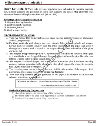
1. Electromagnetic induction is the phenomenon by which a changing magnetic field induces an electromotive force (emf) in a conductor. Experiments by Michael Faraday and Joseph Henry in the 1830s demonstrated this effect and established its laws.
2. Faraday's experiments showed that a changing magnetic flux induces a current in a coil. He placed coils inside changing magnetic fields from moving magnets and observed induced currents.
3. Lenz's law defines the direction of induced current: the current flows such that its magnetic field opposes the change that caused it. This ensures the conservation of energy.
![6.Electromagnetic Induction
Coaching for 8-10th, PU I & II (Sci. & Commerce), NTSE, Olympiad, KVPY, NDA, CET, NEET, JEE. Call: 9663320948 Page 112
INTRODUCTION
Electricity and magnetism were considered separate and unrelated phenomena for a
long time. In the nineteenth century, experiments on electric current by Hans Oersted,
Ampere established the fact that electricity and magnetism are inter-related.
They found that moving electric charges produce magnetic fields. For example, an
electric current deflects a magnetic compass needle placed nearby.
Can moving magnets produce electric currents? The answer is yes! The experiments of
Michael Faraday and Joseph Henry demonstrated that electric currents were induced
in closed coils when subjected to changing magnetic fields.
The phenomenon in which electric current is generated by varying magnetic fields is
appropriately called ELECTROMAGNETIC INDUCTION.
OR
Whenever the magnetic flux linked with an electric circuit changes, an emf is induced in
the circuit. This phenomenon is called ELECTROMAGNETIC INDUCTION
Hans Oersted Experiments: Whenever current passed through the wire it produces magnetic
field around it. The nature of magnetic field is in the form of concentric circles. The direction of
magnetic field given by right hand rule.
THE EXPERIMENTS OF FARADAY AND HENRY: Michael Faraday [1791– 1867]
Faraday made numerous
contributions to science, viz., the
discovery of electromagnetic
induction, the laws of electrolysis,
benzene, and the fact that the plane
of polarisation is rotated in an
electric field. He is also credited
with the invention of the electric
motor, the electric generator and
the transformer. He is widely
regarded as the greatest
experimental scientist of the
nineteenth century.](https://image.slidesharecdn.com/phypuc2notes-112-1261-230602162152-fb8bbf96/85/PHY-PUC-2-Notes-Electromagnetic-induction-1-320.jpg)
![6.Electromagnetic Induction
Coaching for 8-10th Page 113
The discovery and understanding of electromagnetic induction are based on a long
series of experiments carried out by Faraday and Henry
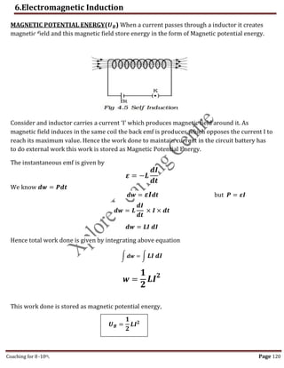
Experiment(1) : Coil and Magnets Experiments
Josheph Henry [1797 – 1878]
American experimental physicist,
professor at Princeton University
and first director of the
Smithsonian Institution. He made
important improvements in
electromagnets by winding coils
of insulated wire around iron
pole pieces and invented an
electromagnetic motor and a
new, efficient telegraph. He
discovered self-induction and
investigated how currents in one
circuit induce currents in
another.
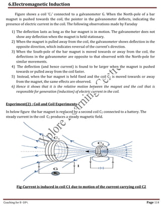
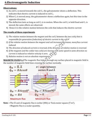
Figure: When the bar magnet is pushed towards the coil, the
pointer in the galvanometer G deflects
,](https://image.slidesharecdn.com/phypuc2notes-112-1261-230602162152-fb8bbf96/85/PHY-PUC-2-Notes-Electromagnetic-induction-2-320.jpg)
![6.Electromagnetic Induction
Coaching for 8-10th Page 119
SELF INDUCTANCE(L): Emf is induced in a single isolated coil due to change of flux
through the coil by means of varying the current through the same coil. This phenomenon is
called self-induction.
i.e. Flux linkage through a coil of N turns is proportional to the current through the coil
∅𝐵 ∝ 𝐼
For N turns,
𝑁∅𝐵 = 𝐿𝐼
Where constant of proportionality L is called self-inductance of the coil. It is also called the
coefficient of self-induction of the coil.
Also from Faradays law the induced emf is given by,
𝜺 = −
𝒅(𝑵∅𝑩)
𝒅𝒕
= −𝑳
𝒅𝑰
𝒅𝒕
𝜺 = −𝑳
𝒅𝑰
𝒅𝒕
The negative sign indicates that emf is opposing the cause producing it.
Self Inductance is a scalar quantity. It has the dimensions of [M L2 T–2 A–2]
The SI unit of self-inductance is Henry and is denoted by H.
Self-inductance of a long solenoid of cross-sectional area A and length l, having n turns
per unit length.
𝑳 = 𝝁𝒐𝒏𝟐
𝑨𝒍 OR 𝑳 =
𝝁𝒐𝑵𝟐𝑨
𝒍
Where ,
𝜇𝑜 =Permeability of free space.
𝑛 = Number of turns per unit length
𝐴 = Cross-sectional area of solenoid
𝑙 = Length of the solenoid
Note: The self-inductance of the coil depends on,
1) Its geometry, shape and size of the solenoid.
2) Permeability of the medium
Back emf: The self-induced emf is also called the back emf as it opposes any change in the
current in a circuit
ONE HENRY(1H):It is the value of self-inductance of a coil in which one volt is produced by a
variation of the inducing current of one ampere per second.
,](https://image.slidesharecdn.com/phypuc2notes-112-1261-230602162152-fb8bbf96/85/PHY-PUC-2-Notes-Electromagnetic-induction-8-320.jpg)
![6.Electromagnetic Induction
Coaching for 8-10th Page 122
𝜺 = −𝑴
𝒅𝑰
𝒅𝒕
The negative sign indicates that emf is opposing the cause producing it.
Self Inductance is a scalar quantity. It has the dimensions of [M L2 T–2 A–2]
The SI unit of mutual-inductance is Henry and is denoted by H.
COEFFICIENT OF MUTUAL INDUCTION :One henry is defined as the coefficient of mutual
induction between a pair of coils when a change of current of one ampere per second in one
coil produces an induced emf of one volt in the other coil
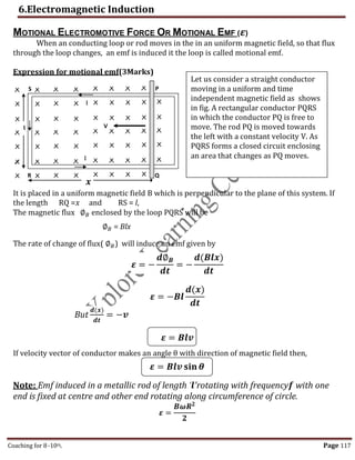
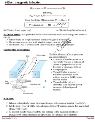
MUTUAL INDUCTANCE BETWEEN THE TWO COILS
Two long co-axial solenoids each of length l. The radius of the solenoid S1 by r1 and the
number of turns per unit length by n1. The corresponding quantities for the other solenoid S2
are r2 and n2, respectively. Let N1 and N2 be the total number of turns of coils S1 and S2,
respectively.
When a current I1 is set up through S1, it sets up a magnetic flux through S2. Let us denote it by
∅2. The corresponding flux linkage with solenoid S2 is,
𝑁2∅2 = 𝑀21𝐼1--------------------(1)
Consider the reverse case, When a current I2 is set up through S2, it sets up a magnetic flux
through S1. Let us denote it by ∅1. The corresponding flux linkage with solenoid S1 is,
𝑁1∅1 = 𝑀12𝐼2-------------(2)
Now we know , 𝐵 = 𝜇0𝑛𝐼 and N=nl apply it to any above equation say (2) then
(𝑛1𝑙)𝜇0𝑛2𝐼1𝐴 = 𝑀21𝐼1 ∅𝐵 = BA
S1
S2
𝜺
Source
,](https://image.slidesharecdn.com/phypuc2notes-112-1261-230602162152-fb8bbf96/85/PHY-PUC-2-Notes-Electromagnetic-induction-11-320.jpg)
![6.Electromagnetic Induction
Coaching for 8-10th Page 125
Physical Quantity Symbol Dimensions Unit
Magnetic field B [𝑳𝟐] Tesla(T)
Magnetic Flux ∅𝐵 [𝑴𝑳𝟐
𝑻−𝟐
𝑨−𝟏] Weber(Wb)
EMF 𝜀 [𝑴𝑳𝟐
𝑻−𝟑
𝑨−𝟏] Volt(V)
Mutual Inductance M [𝑴𝑳𝟐
𝑻−𝟐
𝑨𝟐] Henry(H)
Self Inductance L [𝑴𝑳𝟐
𝑻−𝟐
𝑨𝟐] Henry(H)
ONE MARK QUESTIONS
1. What is electromagnetic induction?
2. Define magnetic flux through a surface.
3. State Faraday’s law of electromagnetic induction.
4. State Lenz’s law of electromagnetic induction.
5. What are eddy currents?
6. Define self-inductance of a coil.
7. Write the S.I unit of self-inductance.
8. Define the S.I unit of self-inductance.
9. What is mutual inductance?
10.Define co-efficient of mutual inductance.
11.What is motional emf?
12.What happens to self-inductance of a coil if a ferromagnetic material is inserted
inside the coil?
13.Mention the expression for magnetic potential energy stored in an inductor
when current flows through it.
14.On what principle AC generator works?
TWO MARK QUESTIONS
1. Define magnetic flux through a surface? Give its mathematical formula in vector form.
2. For what angle of inclination the magnetic flux through the surface is (a)
maximum (b) minimum?
3. State and explain Faraday’s law of electromagnetic induction.
4. A wheel with 10 metallic spokes each 0.5 m long is rotated with a speed of 120 revolutions
per minute in a plane normal to the horizontal component of earth’s magnetic field 0.4 x 10-
4T. What is the induced emf between the axle and the rim of the wheel?
5. State and explain Lenz’s law in electromagnetic induction.
6. Mention two methods of reducing eddy currents.
7. The magnetic flux linked with a coil changes from 12 x 10-3 Wb (Tm2) to 6x10⁻³Wb in 0.01
second. Calculate the induced emf in the coil.
,](https://image.slidesharecdn.com/phypuc2notes-112-1261-230602162152-fb8bbf96/85/PHY-PUC-2-Notes-Electromagnetic-induction-14-320.jpg)
![6.Electromagnetic Induction
th Page 126
8. Give the expression for mutual inductance induced between two co-axial
solenoids and explain the terms.
9. Give an expression for self-inductance of a coil and explain the terms.
10.Draw a neat labeled diagram of AC generator.
THREE MARK QUESTIONS
1. Describe coil and magnet experiment of Faraday and Henry to demonstrate electromagnetic
induction phenomena.
2. Describe coil and coil experiment of Faraday and Henry to demonstrate electromagnetic
induction.
3. Derive the expression for motional emf in a conducting rod moving in uniform magnetic
field.
4. Mention any three applications of eddy currents.
5. Obtain the expression for co-efficient of mutual inductance between two co-axial solenoids.
6. Obtain the expression for energy stored in an inductor.
FIVE MARK QUESTIONS
1. Describe the construction and working of AC generator with a labeled diagram and hence
arrive at the expression for the instantaneous value of emf induced in it.
2. Show that solenoid is equivalent to bar magnet.
NUMERICAL PROBLEMS
1. A circular coil of 100 turns, 0.2m radius has a resistance of 100Ω is held at right angles to a
uniform magnetic field of 2T. it is then turned through 450 about an axis at right angles to
the field. Calculate the charge induced in the coil. [73.5X10⁻³]
2. The electric current in a circuit varies from +2A to -2A in a time interval of 10-2s.another
coil of resistance 20Ω and inductance 2H is placed near it. Find the induced current in the
second coil. [40A]
3. A solenoid of radius 2.5cm, length 0.5m has 500 turns per centimeter. If a current of 1A is
set up in the solenoid calculate the magnetic flux through the solenoid. [3Wb]
4. An iron core is inserted into a solenoid of length 0.5m, area of cross-section 0.001m2 and
400 turns per unit length. Find the permeability of the core if 5A of current produces a
magnetic flux of 1.6X10- 3Wb through it. [636.94]
5. A vertical copper disc of diameter 20cm makes 10 revolutions per second about a
horizontal axis passing through its center. A uniform magnetic field 10-2T acts
perpendicular to the plane of the disc. Calculate the potential difference between its center
and rim. [3.14X10⁻³V]
,](https://image.slidesharecdn.com/phypuc2notes-112-1261-230602162152-fb8bbf96/85/PHY-PUC-2-Notes-Electromagnetic-induction-15-320.jpg)