


![23
represents the ratio of the area of the sub triangle defined by each side, and
the point to the total area of the triangle element.
The shape function is defined as,
(SF)N = 1 at node N
0 at other nodes.
The properties, together with the linearity of the shape functions,
assure the convergence of the solution to the correct values of the function, as
the area of the element becomes infinitely small.
2.2.1.3 Stiffness matrix
To achieve minimization, the global energy is separated into its
element components, by minimizing one triangle at a time. The nonlinearity
of the problem is preserved, since the stiffness matrix [S] depends not only on
the shape and size of each triangle, but also on the reluctivity. The matrix [S]
is equal to the number of node potentials. [S] is also symmetrical, i.e., [S] =
[S]T
. Therefore, only half the bandwidth will be stored; then the matrix is
bounded and positive definite.
2.2.1.4 Solution technique
The most common method for solving the equations is the Newton
Raphson (NR) algorithm. Nowadays, a fast, powerful and general purpose
software is used as part of the finite element technique for solving
electromagnetic field equations. The CAD packages are used as the
simulation tool for the finite element analysis. There are various CAD
packages like Flux 2D, Ansoft, EMTDC, Femta fe, etc. The newly adopted
efficient CAD package used for the finite element analysis is “Magnet”.](https://image.slidesharecdn.com/nagarajansthesis-210330071442/85/Ph-D-thesis-sample-45-320.jpg)


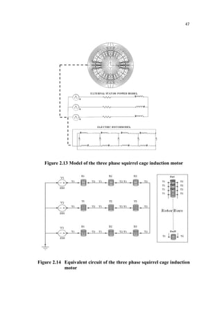


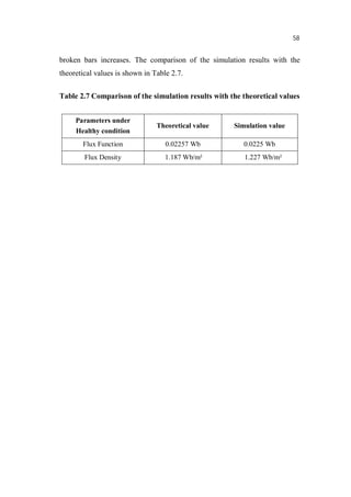


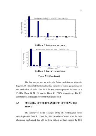

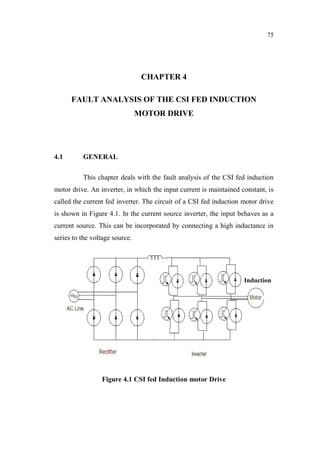
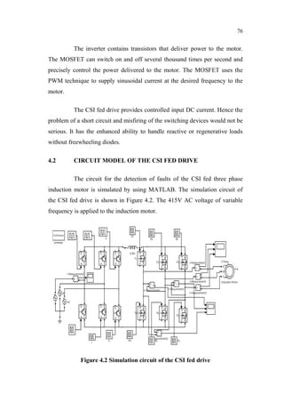


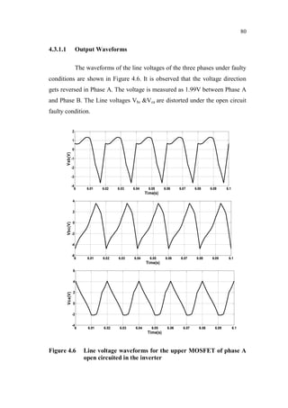


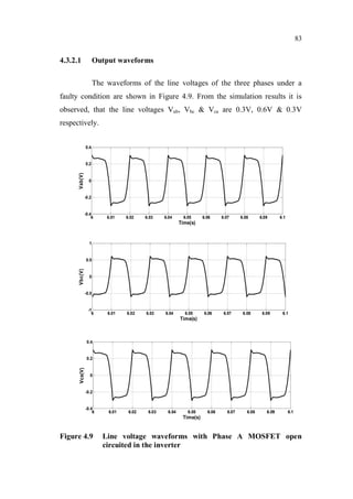
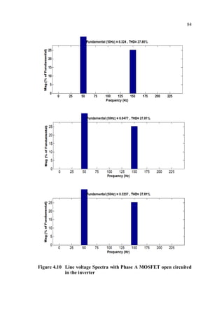
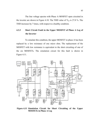


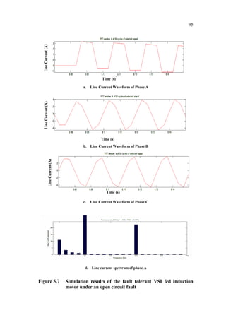


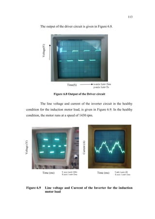

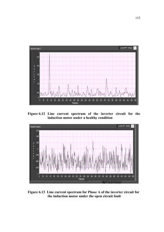


This document is a thesis submitted by Nagarajan S. for the degree of Doctor of Philosophy at Anna University, Chennai, India in November 2013. The thesis investigates fault detection of inverter-fed three-phase squirrel cage induction motors using finite element analysis. It models an induction motor using finite element software and analyzes parameters like flux density and magnetic energy under healthy and faulty rotor bar conditions. It also analyzes faults in voltage source inverters and current source inverters feeding induction motor drives. Finally, it proposes a fault tolerant voltage source inverter to overcome inverter faults.


![[IJET V2I3P12] Authors: France O. Akpojedje, Ese M. Okah, and Yussuf O. Abu](https://cdn.slidesharecdn.com/ss_thumbnails/ijet-v2i3p12-160609053434-thumbnail.jpg?width=640&height=640&fit=bounds)