Downloaded 125 times
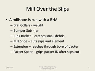


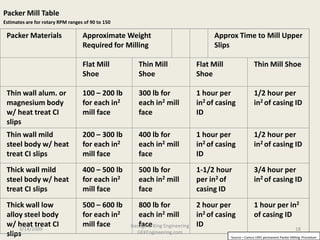


This document discusses various techniques for removing permanent packers and retrievable packers that require more than straight pulls. It describes reasons for removal such as leaks and access to lower zones. Rig-based and coiled tubing removal methods are covered. Specific techniques discussed include milling over the packer slips, using a flat bottom mill, sand line drilling, running a mill shoe and spear, and considerations for special cases. Challenges with nipple milling and examples of packer removal in case histories are also summarized.


