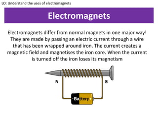
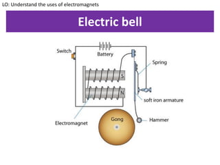
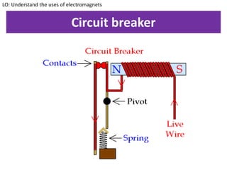
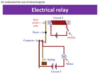
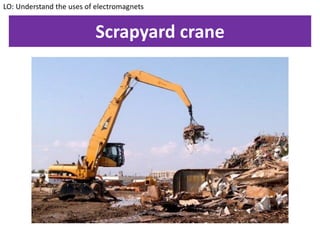
SlideShare a Scribd company logo
P3
KEYWORDS: electromagnet, crane,
Circuit breaker, electric bell, relay
Understand the uses of
electromagnets
ALL – State how to make
an electromagnet
MOST – Describe the
uses of electromagnets
SOME – Evaluate the
uses of electromagnets
Starter
Make a mind map about
everything you remember
about magnets and
electromagnets
Electromagnets
Electromagnets differ from normal magnets in one major way!
They are made by passing an electric current through a wire
that has been wrapped around iron. The current creates a
magnetic field and magnetises the iron core. When the current
is turned off the iron loses its magnetism
LO: Understand the uses of electromagnets
Practical – Electromagnetic strength
1. Increasing the number of coils on an electromagnet
will increase the strength of an electromagnet
2. Certain cores will make an electromagnet stronger
than others
3. Increasing the voltage of the connecting
battery/current passing through the wire will
increase the strength of an electromagnet
LO: Understand the uses of electromagnets
Electric bell
LO: Understand the uses of electromagnets
Circuit breaker
LO: Understand the uses of electromagnets
Electrical relay
LO: Understand the uses of electromagnets
Scrapyard crane
LO: Understand the uses of electromagnets
KEYWORDS: Fleming’s left hand rule
Understand how
electromagnets can be
used to make things
move
ALL – State how
electromagnets can be
used in motors
MOST – Use Fleming’s
left hand rule
SOME – Explain how
loudspeakers work
The Motor Effect
If a wire carrying a current is
placed into a magnetic field, an
interesting thing happens.
As part of the GCSE course, you
are required to know which
way a wire placed into a
magnetic field moves
LO: Understand how electromagnets can be used to make things move
Fleming’s left hand rule
LO: Understand how electromagnets can be used to make things move
Electric Motor
LO: Understand how electromagnets can be used to make things move
An electric motor uses
the motor effect of
electromagnets to create
motion.
• The force on one side
of the wire causes it to
move up
• The force on the other
side of the wire causes
it to move down
• The motor rotates!
Electric Motor
LO: Understand how electromagnets can be used to make things move
Graphite ‘brushes’ are
used to connect the split-
ring to the battery. This is
used because:
• Graphite is an
excellent conductor
• It causes very little
friction on the
conducting ring
The Loudspeaker
LO: Understand how electromagnets can be used to make things move
KEYWORDS: Electromagnetic induction,
Generator, coil, wire, magnet
Understand how
generators create
electricity
ALL – State how
electricity can be
created
MOST – Describe how
electromagnetic
induction can be
increased
SOME – Explain
generators work in
detail
Electromagnetic induction
By moving the magnet within the coil of
wire, current can be induced within the
current. Note, that the current is only
induced when the magnet or coil is
moving!
How can the amount of current induced
be increased?
• Increase the number of coils
• Increase the speed at which the
magnet/coil moves
• Increase the strength of the magnet
LO: Understand how generators create electricity
Electric generators
LO: Understand how generators create electricity
KEYWORDS: transformer, core, step up,
Step down, primary, secondary, induced
Understand how
transformers work
ALL – State the function
of step up and step
down transformers
MOST – Explain how
transformers work and
perform transformer
calculations
SOME – Explain why
values from equations
are just an
approximation
Step-up and Step-down
Transformers are an essential
part of the national grid. They
help to increase the voltage
after the power station and
help to decrease it again
when it gets to your house.
LO: Understand how transformers work
How do transformers work?
Discuss with the people on
your pod how transformers
work. Remember the
following:
• The only work with an a.c.
current
• They need to have an iron
core
• They use electromagnetic
induction to work
LO: Understand how transformers work
How transformers work
1. The alternating current in the primary coil makes the iron
core into an electromagnetic
2. As the current is alternating, the magnetic field ‘moves’
and also changes direction
3. This ‘moving’ magnetic field causes a current to be
induced in the secondary coil
4. If the number of coils on the secondary is higher, the
potential difference will increase and it is a step-up
transformer
5. If the number of coils on the secondary is lower, the
potential difference will decrease and it is a step-down
transformer
LO: Understand how transformers work
Transformer calculations
The following equation links together the voltage and
number of coils in a transformer:
LO: Understand how transformers work
𝑉𝑝
𝑉𝑠
=
𝑛 𝑝
𝑛 𝑠
Vp = Voltage on primary coil (v)
Vs = Voltage on secondary coil (v)
np = number of turns on primary coil
ns = number of turns on secondary coil
Transformer efficiency
Transformers are usually about 98% efficient. We can
round this up and say that this is approximately 100%.
Therefore, whatever power the device uses, it will output
the same amount of power!
Power in = Power out
LO: Understand how transformers work
Transformer efficiency
Power in = Power out
Vp x Ip = Vs x Is
LO: Understand how transformers work
Vp = Voltage on primary coil (v)
Vs = Voltage on secondary coil (v)
Ip = Current on primary coil (A)
Is = Current on secondary coil (A)
KEYWORDS: x-ray, CT scanner, Ultrasound
Understand how
physics can be applied
to medicine
ALL – State some
medical applications of
physics
MOST – Describe how x-
rays, CT scanners and
ultrasound work
SOME – Evaluate the
use of these devices in
particular situations
Starter
Recap questions
Further notes on Ultrasound
Besides using ultrasound to create
pictures of babies, they can also be used
to treat kidney stones!
Kidney stones are small lumps that can
form in the kidneys. They are formed
when small crystals of waste products
filtered by the kidneys build up. When
they are formed, your body will try to
pass them out through the urine.
However, they can sometimes get stuck
in this process and cause immense pain!
LO: Understand how physics can be applied to medicine
Further notes on Ultrasound
Ultrasound can be used to treat kidney
stones. Ultrasound is usually very high
frequency (>20000Hz) outside of the
range of human hearing. If it is directed
at the kidney stones, the high frequency
sound can break them up into smaller
pieces and make it easier for them to
pass out through the urine!
LO: Understand how physics can be applied to medicine
Distance between interfaces
The distance to an object can be found using information from
an ultrasound. It can be found using the following equation:
S = V x T
LO: Understand how physics can be applied to medicine
S = Distance (m)
V = Velocity of sound (m/s)
T = Time (s)
KEYWORDS: refraction, angle of incidence,
Angle of refraction, refractive index
Understand the
phenomena of
refraction
ALL – Describe what
happens during
refraction
MOST – Explain why
refraction occurs
SOME – State the
relationship between
the angle of incidence
and the angle of
refraction
Starter
Refraction mind
map
Refraction
Refraction occurs when light moves
between two mediums that have a
different density. (The word medium
just means ‘something that you can
travel through’)
When light moves into a medium with
a higher density, it slows down and
will bend towards the normal. When
it moves into a less dense medium, it
speeds up and bends away from the
normal.
LO: Understand the phenomena of refraction
Conclusion: Refraction
What can you conclude about the relationship between the
two angles in refraction?
Sin of the angle of incidence divided by Sin of the angle of
refraction will always be a constant. The value of the constant
will change depending on what materials are being used to do
refraction (i.e. refraction with air and glass will have a
different value to air and water and air an oil etc.)
LO: Understand the phenomena of refraction
Refractive Index
The refractive index of a material is a measure of
how much light is refracted by it when it passes
through the material. It can be calculated by using
the equation:
Refractive index = Sin I / Sin R
LO: Understand the phenomena of refraction
I = angle of incidence
R = angle of refraction
KEYWORDS: refraction, angle of incidence,
Angle of refraction, refractive index
Understand how total
internal reflection
occurs
ALL – Describe total
internal reflection
MOST – Perform
calculations for the
critical angle of an
object
SOME – Explain how TIR
is utilised through
endoscopes and optical
fibres
Demonstration: Critical Angle
When performing
refraction with a semi-
circular block, an
interesting phenomena is
observed. When the light
leaves the block, it bends
away from the normal. This
is expected as it is moving
from a more dense to a
less dense medium.
LO: Understand the phenomena of refraction
Demonstration: Critical Angle
As we continue to increase
the angle of incidence, we
reach a point where the
refracted light seems to
run across the top of the
glass block! The angle at
which this happens is
called the ‘critical angle’
LO: Understand the phenomena of refraction
Demonstration: Critical Angle
If we increase the angle
even more, we can see that
the light ray is no longer
refracted. Instead, it seems
to reflect off inside of the
straight edge of the semi-
circular block. This is
known as total internal
reflection
We will explore this in
greater detail later
LO: Understand the phenomena of refraction
Critical Angle
The critical angle of a material can be found using
the following formula:
Refractive index = 1/sin(C)
LO: Understand the phenomena of refraction
Refractive index = property of a material
C = Critical angle
Uses of Total Internal Reflection
Fibre optic cables are able to
work using total internal
reflection. Light is sent through
one end in short bursts and will
light up the other end.
These fibre optic cables are now
used in high speed internet!
They are now also used in
medicine…
LO: Understand how physics can be applied to medicine
Uses of Total Internal Reflection
Total internal reflection is put to
good use in Endoscopes. These
are cameras that can be used to
look inside patients without
having to perform invasive
surgery.
Light is shone into one end,
travels through the endoscope,
shines off the inside of a patient,
back along the endoscope and
forms a picture!
LO: Understand how physics can be applied to medicine
KEYWORDS: converging, diverging, lenses,
Focal point, virtual, real
Understand how to
draw ray diagrams for
lenses
ALL – state the
definition of converging
and diverging
MOST – Draw ray
diagrams for lenses
SOME – Explain when
virtual and real images
are formed when using
lenses
Starter
Make a mind map of
all the objects that
you can think of that
use lenses!
Converging lens
LO: understand how to draw ray diagrams for lenses
A converging lens is always
convex. It makes rays that are
coming in that are parallel
converge onto a point. The
point where the rays
converge is called the
principal focus, or focal
point.
Converging lenses are used in
magnifying glasses and in
cameras.
Diverging lens
LO: understand how to draw ray diagrams for lenses
A diverging lens is always
concave. It makes rays that
are coming in that are parallel
diverge. The point where the
rays seem to diverge from is
called the principal focus, or
focal point.
Diverging lenses are used to
correct short sight
Focal length
LO: understand how to draw ray diagrams for lenses
For both lenses, the distance
between the centre of the
lens and the focal point is
called the focal length.
Real image
LO: understand how to draw ray diagrams for lenses
When an object is really far
away from a converging lens,
the light rays will be (almost)
parallel when they reach the
lens. The image that will be
formed will be at the focal
length.
We call this image a real
image.
Real image
LO: understand how to draw ray diagrams for lenses
A real image is an image that
is formed by a converging
lens if the object is further
away than the principal
focus.
The real image will always be
smaller than the actual
object, inverted and forms
after the lens.
Virtual image
LO: understand how to draw ray diagrams for lenses
When the object is close to a lens, the image that is
formed will be much larger than the actual size of the
object.
We call this image a virtual image.
Virtual image
LO: understand how to draw ray diagrams for lenses
A virtual image is formed by a converging lens if the
object is nearer to the lens than the focal length. A
diverging lens will ALWAYS form a virtual image. The
image is always bigger than the object, the right way up
and forms before the lens.
Magnification
LO: understand how to draw ray diagrams for lenses
The magnification produced by a lens can be worked out
using the following formula
Magnification = image height
object height
Formation of a real image by a converging lens
LO: understand how to draw ray diagrams for lenses
As part of P3, you are required to know how to draw ray
diagrams like the one below to show
Although they look very complicated, they are quite easy
to draw once you know how
Formation of a real image by a converging lens
LO: understand how to draw ray diagrams for lenses
Drawing ray diagrams for a converging lens is done in 4 easy
steps:
1) Draw the principal axis and the lens (always shown as a
line with arrowheads)
2) Draw the object (drawn as a vertical arrow going upwards
3) Draw a line parallel to the principal axis that refracts at the
lens and goes through the focal point
4) Draw a line straight through the principal axis and the lens
line
5) Draw a line that goes through the focal point and refracts
to become parallel at the lens
6) Draw the object on the other side of the lens where the
three construction lines all join up
Uses of Converging lenses
LO: understand how to draw ray diagrams for lenses
This final example shows how a
converging lens can be used as a
magnifying glass. When an object
is placed close to the magnifying
glass (closer than the focal
length), the object will appear
bigger than the actual object. The
image formed is virtual
(remember the definition!) and
will also be the right way up (i.e.
not inverted)
Old Skool uses of converging lenses
LO: understand how to draw ray diagrams for lenses
All cameras have a converging lens. This focuses the light from
distant objects onto a film at the back of the camera. When the
shutter is opened, the film is exposed and a negative is made.
The negative can then be developed into the actual picture!
New Skool uses of converging lenses
LO: understand how to draw ray diagrams for lenses
Newer digital cameras work in the same way. However, instead of
photographic film at the back of the camera, they have a CCD
imager. When the shutter is opened, the CCD is exposed to light
and it forms the image.
New Skool uses of converging lenses
LO: understand how to draw ray diagrams for lenses
When an object is placed too close to a camera, it will appear
fuzzy. This is because the object is closer to the lens than the
focal length and the lens is not able to focus the image properly
onto the CCD.
KEYWORDS: converging, diverging, lenses,
Focal point, virtual, real
Understand the
structure of the eye
ALL – label the different
parts of the eye
MOST – Describe what
different parts of the
eye do
SOME – Explain how
converging and
diverging lenses can be
used to correct for
vision problems
How the eye works
Regardless of if you are
looking at an object very
close to you or very far
away, your eye is able to
focus and you are able to
see the object clearly. How
is your eye able to refocus
based on where the object
is?
LO: understand the structure of the eye
How the eye works
1. When light enters the eye, the
ciliary muscles change the
thickness of the lens
2. The light is focused by your
lens onto the retina
3. The light sensitive cells in the
retina send electrical impulses
through the optic nerve to
your brain
4. Your brain processes these
impulses and shows you what
the object looks like
LO: understand the structure of the eye
What happens if
too much light
suddenly enters
the eye?
Correcting vision
By using our
understanding of how
the eye works and how
lenses work, we can
design glasses to correct
for sight problems
LO: understand the structure of the eye
Short sight
In a normal eye, the lens focuses
the image exactly on the retina.
However, in the eye of a person
with Myopia (short sighted), the
image is formed before the retina.
This leads to a blurred image.
LO: understand the structure of the eye
Correcting short sight
Short sight can be corrected by
glasses that have a concave
(diverging) lens. This causes the
light rays to diffract outwards
slightly as they pass the lens so
that they are focused exactly on
the retina by the lens in the eye.
LO: understand the structure of the eye
Long sight
In a person with ‘hyperopia’ (long
sight), the image is not correctly
focused onto the retina by the eye
lens. The image is focused behind
the retina, leading to a blurry
image.
How can we correct this?
LO: understand the structure of the eye
Correcting long sight
Long sight can be corrected by
using a convex (converging) lens.
This causes the light rays to
converge slightly before they hit
the lens so that they are refracted
perfectly onto the retina.
LO: understand the structure of the eye
Power of a lens
The power of a lens can be worked out using the following
equation:
Power = 1
LO: understand the structure of the eye
Focal length
Power = Dioptre (D)
Focal length = m
To understand how
objects balance
ALL – State the
definition of a moment
MOST – Perform
moment calculations
SOME – Explain how
objects balance using
the concept of moments
What is a moment?
When the mass is placed on the left-hand side of the see-
saw, it moves down. This is an anticlockwise turn
The turning effect of a force is called a moment
LO: Understand how things balance
pivot
Calculating moments
The moment of a force is calculated from:
Moment = force x distance from pivot
m = f x d
LO: Understand how things balance
Moment = Newton – Metres (Nm)
Force = Newtons (N)
Distance = metres (m)
Example 1
Gina weighs 500 N and stands on one end of a seesaw.
She is 0.5 m from the pivot. What moment does she
exert?
LO: Understand how things balance
moment = 500 x 0.5
= 250 Nm
0.5 m
500 N
pivot
Example 2
If a force of 20 N presses down at a distance of 3 m from a
pivot, its moment is:
Moment = 20 N x 3 m = 60 Nm
LO: Understand how things balance
Example 3
If a force of 30 N presses down at a distance of 4 m from a
pivot, its moment is:
Moment = 30 N x 4 m = 60 Nm
LO: Understand how things balance
Moments in balance
A seesaw is an example of the principle of moments. This
states that for an object in equilibrium (not moving!) the
sum of all the clockwise moments about any point is
equal to the sum of all the anticlockwise moments about
the same point.
Clockwise moments = anticlockwise moments
W1 x D1 = W2 x D2
LO: Understand how things balance
Calculating moments
Task: Answer the questions on calculating moments on
the worksheet. The second side is more difficult than the
first!
Moment = force x distance from pivot
LO: Understand how things balance
What do these objects have in common?
LO: Understand how things balance
KEYWORDS: centre of mass, line of
symmetry
Understand what is
meant by centre of
mass
ALL – Define the
centre of mass
MOST – be able to find
the centre of mass of
symmetrical objects
SOME – Explain why
objects are designed
to have a low centre of
mass
Starter
What do these objects have
in common?
Centre of Mass
LO: Understand what is meant by centre of mass
For all objects, their
mass is spread out over
the whole object.
However, this is not
useful to us as
Physicists!
Centre of Mass
LO: Understand what is meant by centre of mass
The centre of mass of
an object is that point
at which the mass may
thought to be
concentrated
Finding the centre of mass
LO: Understand what is meant by centre of mass
The centre of mass of
complicated objects can
be incredibly difficult to
find. However, for
simple, symmetrical
objects, the COM can be
easily found!
Centre of mass of symmetrical objects
LO: Understand what is meant by centre of mass
The centre of mass of
symmetrical objects
ALWAYS lies along the
line of symmetry of the
object. Where the
object has more than
one line of symmetry,
the COM will be at the
point where the lines of
symmetry intersect
Suspended objects
LO: Understand what is meant by centre of mass
If you suspend an object
and then release it, it
will soon come to a rest.
When this happens, the
centre of mass will be
directly below the point
of suspension. The
object can be said to be
in equilibrium.
Demo
Irregular shapes
LO: Understand what is meant by centre of mass
The centre of mass of an
irregular shape can be found by
using the apparatus shown. The
shape is hung from a point and
a plumbline used to draw the
region in which the COM lies.
This is done repeatedly with the
mass hung from different
points. The point where all the
lines intersect is the COM!
KEYWORDS: centre of mass, stability,
Moment, base, tractor
Understand how to
design stable objects
ALL – state features of
stable objects
MOST – Explain what
happens when objects
topple over
SOME – Evaluate the
design of objects based
on their stability
Starter
Challenge
starter!
The designers of this bus are worried that it will
topple over. They are testing it to find out the
maximum angle it can go to before this happens.
Using your knowledge of science and as many
scientific terms as possible, explain WHY this bus
is likely to topple over easily!
Keywords:
• Centre of mass
• Moment
• Pivot
• Base
• Topple
Stable objects
Although the design of cars
has changed drastically over
the last 100 years, a number
of things have remained
constant. Amongst them is
to keep cars as low as
possible. This means that
the centre of mass of the
car is low and it is less likely
to topple over!
LO: understand how to design stable objects
Why do objects tips over?
The weight of an object acts
through the centre of mass.
As the object is initially
tilted, the weight is causing
an anticlockwise moment
about the pivot. If the
object is let go, the moment
will cause the object to go
back onto its base.
LO: understand how to design stable objects
Why do objects tips over?
As the object continues to
be tilted, you will reach a
point where the weight will
go exactly through the pivot.
LO: understand how to design stable objects
Why do objects tips over?
When the object has been
tilted beyond a certain
point, the weight will now
cause a clockwise moment
about the pivot. If the
object is let go, the moment
will cause the object to
topple over!
LO: understand how to design stable objects
Designing stable objects
LO: understand how to design stable objects
Farmers must be careful
when driving tractors on
slopes. If the slope is too
steep, the tractor may
topple over. To limit the
chances of this happening,
tractors usually have a
large base
Designing stable objects
LO: understand how to design stable objects
This bus is being tested to
find the maximum angle it
can be tilted to before it
topples over. This is
important for road safety
as it will affect the
maximum speed that a
driver can go around a
corner.
High chairs
LO: understand how to design stable objects
A high chair has a centre
of mass that is very high
off the ground. This can
make the chair very
unstable, particularly
when there is a baby
strapped in! To make sure
the chair does not topple
over, it is designed to have
a wide base.
KEYWORDS: Pressure, force, area, hydraulics
Understand pressure in
liquids
ALL – State the
definition of pressure
MOST – Perform
calculations involving
pressure
SOME – Explain how
pressure is used in
hydraulic machines
Starter
List as many situations as you
can where you might be under
pressure!
Pressure
LO: understand pressure in liquids
Pressure is defined as the force per unit area. The
unit of pressure is the pascal (Pa), which is equal
to one newton per square metre (N/m²)
Calculating pressure
LO: understand pressure in liquids
Pressure can be calculated using the following
equation:
Pressure = Force / Area
Pressure = pascals (Pa)
Force = Newtons (N)
Area = metres² (m²)
Hydraulic pressure
Hydraulic pressure is pressure that is caused by a liquid.
Pressure in a liquid is caused by
the weight of the water above.
Pressure in a liquid:
 Acts in all directions
 Increases with depth
LO: understand pressure in liquids
Hydraulic pressure
Dams are built with the base of the dam considerably thicker
than the top. Use your knowledge of pressure to explain why.
LO: understand pressure in liquids
Demonstration: Archimedes can
The Archimedes can
shows us how the
pressure of a liquid
increases with depth
LO: understand pressure in liquids
Hydraulic machines
LO: understand pressure in liquids
Hydraulic machines
LO: understand pressure in liquids
We can use hydraulic pressure
in machines to make things
move. Liquids are almost
incompressible. This means that
if a force is applied to liquid in
one part of the system, it will
move and transfer the force to
another part of the system. This
can be used to squeeze brakes
or move earth in a digger!
Force multipliers
LO: understand pressure in liquids
Force multipliers
LO: understand pressure in liquids
The calculation that we
have just done shows
how pressure can be
used in hydraulic
systems to make forces
bigger. However, this
will only work if:
• The liquid is
incompressible
• A2 is bigger than A1
KEYWORDS: centripetal force, radius,
Velocity, tangent
Understand circular
motion
ALL – State situations
where objects move in a
circle
MOST – Explain what is
required for objects to
move in a circle
SOME – Explain what
happens to the
centripetal force due to
changes in radius and
velocity
Starter
Make a mind map of
objects/situations where things
move continuously in a circle
Circular motion
All the situations that
we have just listed
involve circular
motion. The objects
are moving in a circle
of constant radius with
a constant speed.
Is the velocity of the
object the same?
LO: understand circular motion
Requirements of circular motion
For an object to move in
circular motion:
• The velocity is
tangent to the circle
• The velocity changes
as the object moves
around the circle
• The velocity keeps
the object orbiting in
a circle
LO: understand circular motion
Centripetal force
When an object moves
with circular motion,
there must be a force
acting on it. This force is
called the centripetal
force and causes the
object to accelerate
towards the centre of
the circle.
LO: understand circular motion
What is the centripetal force?
LO: understand circular motion
 Electrostatic force…
 Friction…
 Gravity…
 Tension…
 A car travelling around
a bend
 A stone whirled around
on the end of a string
 A planet moving
around the sun
 An electron orbiting
the nucleus
More or less force?
Discuss with the people
on your pod what effect
there will be on the
centripetal force if:
1. The speed of rotation
is increased
2. The radius is
decreased
3. The mass of the
object is increased
LO: understand circular motion
More or less force?
If you want to:
1. Increase the speed of
rotation
2. Decrease the radius
3. Increase the mass of
the object
The centripetal force
must also be increased.
To do the opposite, the
centripetal force must be
decreased.
LO: understand circular motion
KEYWORDS: oscillating, pendulum,
Frequency, time period
Understand the motion
of a pendulum
ALL – Define the motion
of a pendulum
MOST – Explain how the
time period of a
pendulum can be
increased
SOME – Perform
calculations involving
time period and
frequency
The pendulum
The picture shows a
snapshot of a pendulum in
motion. The pendulum
moves backwards and
forwards and always returns
back to the middle, called
the equilibrium position.
This type of motion is called
oscillating motion.
LO: understand the motion of a pendulum
Time period
The time period of a
pendulum is the time it
takes for a pendulum to
complete one full cycle of
motion. The easiest way to
measure this is the time it
takes for the pendulum to
swing from one side of the
pendulum to the other side
and back again.
LO: understand the motion of a pendulum
What affects the time period?
The factors that affect the
time period of a pendulum
are:
1. The length of the
pendulum
2. The amplitude
(maximum
displacement) of the
swing
LO: understand the motion of a pendulum
Calculating time period
The time period of a pendulum can be calculated
using the following formula:
T = 1 / f
LO: understand the motion of a pendulum
T = Time (s)
f = frequency (Hz)

More Related Content

What's hot

Electricity & Magnetism
Electricity & MagnetismElectricity & Magnetism
Electricity & Magnetismitutor
 
Electricity&Magnetism
Electricity&MagnetismElectricity&Magnetism
Electricity&Magnetism
cmcelraft
 
Electricity and magnetism
Electricity and magnetismElectricity and magnetism
Electricity and magnetism
KANNAN
 
Electricity and magnetism chapter 2 and 3 notes
Electricity and magnetism chapter 2 and 3 notesElectricity and magnetism chapter 2 and 3 notes
Electricity and magnetism chapter 2 and 3 notescjjonesin
 
Electromagnetism Fundamentals
Electromagnetism FundamentalsElectromagnetism Fundamentals
Electromagnetism Fundamentals
Taimoor Muzaffar Gondal
 
Electricity and magnetism
Electricity and magnetismElectricity and magnetism
Electricity and magnetism
Rodtips
 
Electricity magnetism & electromagnetic induction
Electricity magnetism & electromagnetic inductionElectricity magnetism & electromagnetic induction
Electricity magnetism & electromagnetic induction
Anita Malhotra
 
P.p.t for electricity and magnetism
P.p.t for electricity and magnetismP.p.t for electricity and magnetism
P.p.t for electricity and magnetism
omneya_ghis ghis
 
Magnetism ppt
Magnetism pptMagnetism ppt
Magnetism ppt
Shivam Agarwal
 
ELECTROSTATIC INDUCTION
ELECTROSTATIC INDUCTIONELECTROSTATIC INDUCTION
ELECTROSTATIC INDUCTION
Sheeba vinilan
 
G 10 electricity and magnetism lecture & q
G 10 electricity and magnetism lecture & qG 10 electricity and magnetism lecture & q
G 10 electricity and magnetism lecture & q
jEvz Dacunes-Carbonquillo
 
Magnetism
MagnetismMagnetism
Magnetism
SamDesc
 
Physics project on cyclotron class 12th
Physics project on cyclotron class 12thPhysics project on cyclotron class 12th
Physics project on cyclotron class 12th
Ekansh Wagadare
 
PREFINAL
PREFINALPREFINAL
PREFINAL
jeric lora
 
Electricity and Magnetism
Electricity and MagnetismElectricity and Magnetism
Electricity and Magnetism
Hanna Elise
 
Igcse physics part 3
Igcse physics part 3Igcse physics part 3
Igcse physics part 3Momina Mateen
 
Power point electricity and magnetism (4)
Power point electricity and magnetism (4)Power point electricity and magnetism (4)
Power point electricity and magnetism (4)
Mary Sue McMichael
 
Physics Investigatory Project - Class 12 - Tangent Galvanometer
Physics Investigatory Project - Class 12 - Tangent GalvanometerPhysics Investigatory Project - Class 12 - Tangent Galvanometer
Physics Investigatory Project - Class 12 - Tangent Galvanometer
Dhananjay Dhiman
 

What's hot (20)

Electricity & Magnetism
Electricity & MagnetismElectricity & Magnetism
Electricity & Magnetism
 
Electricity&Magnetism
Electricity&MagnetismElectricity&Magnetism
Electricity&Magnetism
 
Electricity and magnetism
Electricity and magnetismElectricity and magnetism
Electricity and magnetism
 
40697676 magnetism
40697676 magnetism40697676 magnetism
40697676 magnetism
 
Electricity and magnetism chapter 2 and 3 notes
Electricity and magnetism chapter 2 and 3 notesElectricity and magnetism chapter 2 and 3 notes
Electricity and magnetism chapter 2 and 3 notes
 
Electromagnetism Fundamentals
Electromagnetism FundamentalsElectromagnetism Fundamentals
Electromagnetism Fundamentals
 
Electricity and magnetism
Electricity and magnetismElectricity and magnetism
Electricity and magnetism
 
Electricity magnetism & electromagnetic induction
Electricity magnetism & electromagnetic inductionElectricity magnetism & electromagnetic induction
Electricity magnetism & electromagnetic induction
 
P.p.t for electricity and magnetism
P.p.t for electricity and magnetismP.p.t for electricity and magnetism
P.p.t for electricity and magnetism
 
Magnetism ppt
Magnetism pptMagnetism ppt
Magnetism ppt
 
ELECTROSTATIC INDUCTION
ELECTROSTATIC INDUCTIONELECTROSTATIC INDUCTION
ELECTROSTATIC INDUCTION
 
G 10 electricity and magnetism lecture & q
G 10 electricity and magnetism lecture & qG 10 electricity and magnetism lecture & q
G 10 electricity and magnetism lecture & q
 
Magnetism
MagnetismMagnetism
Magnetism
 
Physics project on cyclotron class 12th
Physics project on cyclotron class 12thPhysics project on cyclotron class 12th
Physics project on cyclotron class 12th
 
Ch05
Ch05Ch05
Ch05
 
PREFINAL
PREFINALPREFINAL
PREFINAL
 
Electricity and Magnetism
Electricity and MagnetismElectricity and Magnetism
Electricity and Magnetism
 
Igcse physics part 3
Igcse physics part 3Igcse physics part 3
Igcse physics part 3
 
Power point electricity and magnetism (4)
Power point electricity and magnetism (4)Power point electricity and magnetism (4)
Power point electricity and magnetism (4)
 
Physics Investigatory Project - Class 12 - Tangent Galvanometer
Physics Investigatory Project - Class 12 - Tangent GalvanometerPhysics Investigatory Project - Class 12 - Tangent Galvanometer
Physics Investigatory Project - Class 12 - Tangent Galvanometer
 

Similar to P3 powerpoint frog

Electricity653
Electricity653Electricity653
Electricity653
mjacobs68
 
MIT6_007S11_lec37.ppt
MIT6_007S11_lec37.pptMIT6_007S11_lec37.ppt
MIT6_007S11_lec37.ppt
AnshKarwa
 
photon moveent engineering syllabus 1.ppt
photon moveent engineering syllabus 1.pptphoton moveent engineering syllabus 1.ppt
photon moveent engineering syllabus 1.ppt
vicide8204
 
MIT6_007S11_le c37.ppt
MIT6_007S11_le                               c37.pptMIT6_007S11_le                               c37.ppt
MIT6_007S11_le c37.ppt
sshashank1397
 
Electric current.pptx
Electric current.pptxElectric current.pptx
Electric current.pptx
theresabalatico1
 
Quantum physics
Quantum physicsQuantum physics
Quantum physics
Jahanara Jabbar
 
Cyclotron
CyclotronCyclotron
Cyclotron
Ashutosh Singh
 
unit iii.pptx
unit iii.pptxunit iii.pptx
unit iii.pptx
Mohan313217
 
2.ir jntu pharmacy
2.ir jntu pharmacy2.ir jntu pharmacy
2.ir jntu pharmacy
Dr. Suman Pattanayak
 
Physics 33 electromagnetic effects 2
Physics 33   electromagnetic effects 2Physics 33   electromagnetic effects 2
Physics 33 electromagnetic effects 2
Nurul Fadhilah
 
Unit iii (advances in metrology)
Unit iii (advances in metrology)Unit iii (advances in metrology)
Unit iii (advances in metrology)
GAGNGKM
 
Unit III
Unit IIIUnit III
Unit III
DEVARAJMECH
 
16 Mar 26 Soap Bubble, Photoelectric, Wave Particle Duality Actual
16 Mar 26 Soap Bubble, Photoelectric, Wave Particle Duality Actual16 Mar 26 Soap Bubble, Photoelectric, Wave Particle Duality Actual
16 Mar 26 Soap Bubble, Photoelectric, Wave Particle Duality Actual
Steve Koch
 
ULTRASONICS
ULTRASONICSULTRASONICS
ULTRASONICS
Akash Zalavadia
 

Similar to P3 powerpoint frog (20)

Electricity653
Electricity653Electricity653
Electricity653
 
Magnetism
MagnetismMagnetism
Magnetism
 
MIT6_007S11_lec37.ppt
MIT6_007S11_lec37.pptMIT6_007S11_lec37.ppt
MIT6_007S11_lec37.ppt
 
photon moveent engineering syllabus 1.ppt
photon moveent engineering syllabus 1.pptphoton moveent engineering syllabus 1.ppt
photon moveent engineering syllabus 1.ppt
 
MIT6_007S11_le c37.ppt
MIT6_007S11_le                               c37.pptMIT6_007S11_le                               c37.ppt
MIT6_007S11_le c37.ppt
 
Electric current.pptx
Electric current.pptxElectric current.pptx
Electric current.pptx
 
Quantum physics
Quantum physicsQuantum physics
Quantum physics
 
Basic Electrical Theory Bitter
Basic Electrical Theory   BitterBasic Electrical Theory   Bitter
Basic Electrical Theory Bitter
 
Cyclotron
CyclotronCyclotron
Cyclotron
 
Unit i edited
Unit   i editedUnit   i edited
Unit i edited
 
unit iii.pptx
unit iii.pptxunit iii.pptx
unit iii.pptx
 
2.ir jntu pharmacy
2.ir jntu pharmacy2.ir jntu pharmacy
2.ir jntu pharmacy
 
C H6
C H6C H6
C H6
 
Physics 33 electromagnetic effects 2
Physics 33   electromagnetic effects 2Physics 33   electromagnetic effects 2
Physics 33 electromagnetic effects 2
 
Transistor Tester
Transistor TesterTransistor Tester
Transistor Tester
 
Lecture 4 (1)
Lecture 4 (1)Lecture 4 (1)
Lecture 4 (1)
 
Unit iii (advances in metrology)
Unit iii (advances in metrology)Unit iii (advances in metrology)
Unit iii (advances in metrology)
 
Unit III
Unit IIIUnit III
Unit III
 
16 Mar 26 Soap Bubble, Photoelectric, Wave Particle Duality Actual
16 Mar 26 Soap Bubble, Photoelectric, Wave Particle Duality Actual16 Mar 26 Soap Bubble, Photoelectric, Wave Particle Duality Actual
16 Mar 26 Soap Bubble, Photoelectric, Wave Particle Duality Actual
 
ULTRASONICS
ULTRASONICSULTRASONICS
ULTRASONICS
 

Recently uploaded

How to Create Map Views in the Odoo 17 ERP
How to Create Map Views in the Odoo 17 ERPHow to Create Map Views in the Odoo 17 ERP
How to Create Map Views in the Odoo 17 ERP
Celine George
 
aaaaaaaaaaaaaaaaaaaaaaaaaaaaaaaaaaaaaaaaaaaaaaaaaaaaaaa
aaaaaaaaaaaaaaaaaaaaaaaaaaaaaaaaaaaaaaaaaaaaaaaaaaaaaaaaaaaaaaaaaaaaaaaaaaaaaaaaaaaaaaaaaaaaaaaaaaaaaaaaaaaaaa
aaaaaaaaaaaaaaaaaaaaaaaaaaaaaaaaaaaaaaaaaaaaaaaaaaaaaaa
siemaillard
 
1.4 modern child centered education - mahatma gandhi-2.pptx
1.4 modern child centered education - mahatma gandhi-2.pptx1.4 modern child centered education - mahatma gandhi-2.pptx
1.4 modern child centered education - mahatma gandhi-2.pptx
JosvitaDsouza2
 
Basic phrases for greeting and assisting costumers
Basic phrases for greeting and assisting costumersBasic phrases for greeting and assisting costumers
Basic phrases for greeting and assisting costumers
PedroFerreira53928
 
CLASS 11 CBSE B.St Project AIDS TO TRADE - INSURANCE
CLASS 11 CBSE B.St Project AIDS TO TRADE - INSURANCECLASS 11 CBSE B.St Project AIDS TO TRADE - INSURANCE
CLASS 11 CBSE B.St Project AIDS TO TRADE - INSURANCE
BhavyaRajput3
 
TESDA TM1 REVIEWER FOR NATIONAL ASSESSMENT WRITTEN AND ORAL QUESTIONS WITH A...
TESDA TM1 REVIEWER  FOR NATIONAL ASSESSMENT WRITTEN AND ORAL QUESTIONS WITH A...TESDA TM1 REVIEWER  FOR NATIONAL ASSESSMENT WRITTEN AND ORAL QUESTIONS WITH A...
TESDA TM1 REVIEWER FOR NATIONAL ASSESSMENT WRITTEN AND ORAL QUESTIONS WITH A...
EugeneSaldivar
 
Phrasal Verbs.XXXXXXXXXXXXXXXXXXXXXXXXXX
Phrasal Verbs.XXXXXXXXXXXXXXXXXXXXXXXXXXPhrasal Verbs.XXXXXXXXXXXXXXXXXXXXXXXXXX
Phrasal Verbs.XXXXXXXXXXXXXXXXXXXXXXXXXX
MIRIAMSALINAS13
 
Additional Benefits for Employee Website.pdf
Additional Benefits for Employee Website.pdfAdditional Benefits for Employee Website.pdf
Additional Benefits for Employee Website.pdf
joachimlavalley1
 
Sectors of the Indian Economy - Class 10 Study Notes pdf
Sectors of the Indian Economy - Class 10 Study Notes pdfSectors of the Indian Economy - Class 10 Study Notes pdf
Sectors of the Indian Economy - Class 10 Study Notes pdf
Vivekanand Anglo Vedic Academy
 
Synthetic Fiber Construction in lab .pptx
Synthetic Fiber Construction in lab .pptxSynthetic Fiber Construction in lab .pptx
Synthetic Fiber Construction in lab .pptx
Pavel ( NSTU)
 
ESC Beyond Borders _From EU to You_ InfoPack general.pdf
ESC Beyond Borders _From EU to You_ InfoPack general.pdfESC Beyond Borders _From EU to You_ InfoPack general.pdf
ESC Beyond Borders _From EU to You_ InfoPack general.pdf
Fundacja Rozwoju Społeczeństwa Przedsiębiorczego
 
How to Make a Field invisible in Odoo 17
How to Make a Field invisible in Odoo 17How to Make a Field invisible in Odoo 17
How to Make a Field invisible in Odoo 17
Celine George
 
Operation Blue Star - Saka Neela Tara
Operation Blue Star   -  Saka Neela TaraOperation Blue Star   -  Saka Neela Tara
Operation Blue Star - Saka Neela Tara
Balvir Singh
 
Model Attribute Check Company Auto Property
Model Attribute  Check Company Auto PropertyModel Attribute  Check Company Auto Property
Model Attribute Check Company Auto Property
Celine George
 
How libraries can support authors with open access requirements for UKRI fund...
How libraries can support authors with open access requirements for UKRI fund...How libraries can support authors with open access requirements for UKRI fund...
How libraries can support authors with open access requirements for UKRI fund...
Jisc
 
Template Jadual Bertugas Kelas (Boleh Edit)
Template Jadual Bertugas Kelas (Boleh Edit)Template Jadual Bertugas Kelas (Boleh Edit)
Template Jadual Bertugas Kelas (Boleh Edit)
rosedainty
 
Instructions for Submissions thorugh G- Classroom.pptx
Instructions for Submissions thorugh G- Classroom.pptxInstructions for Submissions thorugh G- Classroom.pptx
Instructions for Submissions thorugh G- Classroom.pptx
Jheel Barad
 
Thesis Statement for students diagnonsed withADHD.ppt
Thesis Statement for students diagnonsed withADHD.pptThesis Statement for students diagnonsed withADHD.ppt
Thesis Statement for students diagnonsed withADHD.ppt
EverAndrsGuerraGuerr
 
Unit 8 - Information and Communication Technology (Paper I).pdf
Unit 8 - Information and Communication Technology (Paper I).pdfUnit 8 - Information and Communication Technology (Paper I).pdf
Unit 8 - Information and Communication Technology (Paper I).pdf
Thiyagu K
 
Chapter 3 - Islamic Banking Products and Services.pptx
Chapter 3 - Islamic Banking Products and Services.pptxChapter 3 - Islamic Banking Products and Services.pptx
Chapter 3 - Islamic Banking Products and Services.pptx
Mohd Adib Abd Muin, Senior Lecturer at Universiti Utara Malaysia
 

Recently uploaded (20)

How to Create Map Views in the Odoo 17 ERP
How to Create Map Views in the Odoo 17 ERPHow to Create Map Views in the Odoo 17 ERP
How to Create Map Views in the Odoo 17 ERP
 
aaaaaaaaaaaaaaaaaaaaaaaaaaaaaaaaaaaaaaaaaaaaaaaaaaaaaaa
aaaaaaaaaaaaaaaaaaaaaaaaaaaaaaaaaaaaaaaaaaaaaaaaaaaaaaaaaaaaaaaaaaaaaaaaaaaaaaaaaaaaaaaaaaaaaaaaaaaaaaaaaaaaaa
aaaaaaaaaaaaaaaaaaaaaaaaaaaaaaaaaaaaaaaaaaaaaaaaaaaaaaa
 
1.4 modern child centered education - mahatma gandhi-2.pptx
1.4 modern child centered education - mahatma gandhi-2.pptx1.4 modern child centered education - mahatma gandhi-2.pptx
1.4 modern child centered education - mahatma gandhi-2.pptx
 
Basic phrases for greeting and assisting costumers
Basic phrases for greeting and assisting costumersBasic phrases for greeting and assisting costumers
Basic phrases for greeting and assisting costumers
 
CLASS 11 CBSE B.St Project AIDS TO TRADE - INSURANCE
CLASS 11 CBSE B.St Project AIDS TO TRADE - INSURANCECLASS 11 CBSE B.St Project AIDS TO TRADE - INSURANCE
CLASS 11 CBSE B.St Project AIDS TO TRADE - INSURANCE
 
TESDA TM1 REVIEWER FOR NATIONAL ASSESSMENT WRITTEN AND ORAL QUESTIONS WITH A...
TESDA TM1 REVIEWER  FOR NATIONAL ASSESSMENT WRITTEN AND ORAL QUESTIONS WITH A...TESDA TM1 REVIEWER  FOR NATIONAL ASSESSMENT WRITTEN AND ORAL QUESTIONS WITH A...
TESDA TM1 REVIEWER FOR NATIONAL ASSESSMENT WRITTEN AND ORAL QUESTIONS WITH A...
 
Phrasal Verbs.XXXXXXXXXXXXXXXXXXXXXXXXXX
Phrasal Verbs.XXXXXXXXXXXXXXXXXXXXXXXXXXPhrasal Verbs.XXXXXXXXXXXXXXXXXXXXXXXXXX
Phrasal Verbs.XXXXXXXXXXXXXXXXXXXXXXXXXX
 
Additional Benefits for Employee Website.pdf
Additional Benefits for Employee Website.pdfAdditional Benefits for Employee Website.pdf
Additional Benefits for Employee Website.pdf
 
Sectors of the Indian Economy - Class 10 Study Notes pdf
Sectors of the Indian Economy - Class 10 Study Notes pdfSectors of the Indian Economy - Class 10 Study Notes pdf
Sectors of the Indian Economy - Class 10 Study Notes pdf
 
Synthetic Fiber Construction in lab .pptx
Synthetic Fiber Construction in lab .pptxSynthetic Fiber Construction in lab .pptx
Synthetic Fiber Construction in lab .pptx
 
ESC Beyond Borders _From EU to You_ InfoPack general.pdf
ESC Beyond Borders _From EU to You_ InfoPack general.pdfESC Beyond Borders _From EU to You_ InfoPack general.pdf
ESC Beyond Borders _From EU to You_ InfoPack general.pdf
 
How to Make a Field invisible in Odoo 17
How to Make a Field invisible in Odoo 17How to Make a Field invisible in Odoo 17
How to Make a Field invisible in Odoo 17
 
Operation Blue Star - Saka Neela Tara
Operation Blue Star   -  Saka Neela TaraOperation Blue Star   -  Saka Neela Tara
Operation Blue Star - Saka Neela Tara
 
Model Attribute Check Company Auto Property
Model Attribute  Check Company Auto PropertyModel Attribute  Check Company Auto Property
Model Attribute Check Company Auto Property
 
How libraries can support authors with open access requirements for UKRI fund...
How libraries can support authors with open access requirements for UKRI fund...How libraries can support authors with open access requirements for UKRI fund...
How libraries can support authors with open access requirements for UKRI fund...
 
Template Jadual Bertugas Kelas (Boleh Edit)
Template Jadual Bertugas Kelas (Boleh Edit)Template Jadual Bertugas Kelas (Boleh Edit)
Template Jadual Bertugas Kelas (Boleh Edit)
 
Instructions for Submissions thorugh G- Classroom.pptx
Instructions for Submissions thorugh G- Classroom.pptxInstructions for Submissions thorugh G- Classroom.pptx
Instructions for Submissions thorugh G- Classroom.pptx
 
Thesis Statement for students diagnonsed withADHD.ppt
Thesis Statement for students diagnonsed withADHD.pptThesis Statement for students diagnonsed withADHD.ppt
Thesis Statement for students diagnonsed withADHD.ppt
 
Unit 8 - Information and Communication Technology (Paper I).pdf
Unit 8 - Information and Communication Technology (Paper I).pdfUnit 8 - Information and Communication Technology (Paper I).pdf
Unit 8 - Information and Communication Technology (Paper I).pdf
 
Chapter 3 - Islamic Banking Products and Services.pptx
Chapter 3 - Islamic Banking Products and Services.pptxChapter 3 - Islamic Banking Products and Services.pptx
Chapter 3 - Islamic Banking Products and Services.pptx
 

P3 powerpoint frog

  • 1. P3
  • 2. KEYWORDS: electromagnet, crane, Circuit breaker, electric bell, relay Understand the uses of electromagnets ALL – State how to make an electromagnet MOST – Describe the uses of electromagnets SOME – Evaluate the uses of electromagnets Starter Make a mind map about everything you remember about magnets and electromagnets
  • 3. Electromagnets Electromagnets differ from normal magnets in one major way! They are made by passing an electric current through a wire that has been wrapped around iron. The current creates a magnetic field and magnetises the iron core. When the current is turned off the iron loses its magnetism LO: Understand the uses of electromagnets
  • 4. Practical – Electromagnetic strength 1. Increasing the number of coils on an electromagnet will increase the strength of an electromagnet 2. Certain cores will make an electromagnet stronger than others 3. Increasing the voltage of the connecting battery/current passing through the wire will increase the strength of an electromagnet LO: Understand the uses of electromagnets
  • 5. Electric bell LO: Understand the uses of electromagnets
  • 6. Circuit breaker LO: Understand the uses of electromagnets
  • 7. Electrical relay LO: Understand the uses of electromagnets
  • 8. Scrapyard crane LO: Understand the uses of electromagnets
  • 9. KEYWORDS: Fleming’s left hand rule Understand how electromagnets can be used to make things move ALL – State how electromagnets can be used in motors MOST – Use Fleming’s left hand rule SOME – Explain how loudspeakers work
  • 10. The Motor Effect If a wire carrying a current is placed into a magnetic field, an interesting thing happens. As part of the GCSE course, you are required to know which way a wire placed into a magnetic field moves LO: Understand how electromagnets can be used to make things move
  • 11. Fleming’s left hand rule LO: Understand how electromagnets can be used to make things move
  • 12. Electric Motor LO: Understand how electromagnets can be used to make things move An electric motor uses the motor effect of electromagnets to create motion. • The force on one side of the wire causes it to move up • The force on the other side of the wire causes it to move down • The motor rotates!
  • 13. Electric Motor LO: Understand how electromagnets can be used to make things move Graphite ‘brushes’ are used to connect the split- ring to the battery. This is used because: • Graphite is an excellent conductor • It causes very little friction on the conducting ring
  • 14. The Loudspeaker LO: Understand how electromagnets can be used to make things move
  • 15. KEYWORDS: Electromagnetic induction, Generator, coil, wire, magnet Understand how generators create electricity ALL – State how electricity can be created MOST – Describe how electromagnetic induction can be increased SOME – Explain generators work in detail
  • 16. Electromagnetic induction By moving the magnet within the coil of wire, current can be induced within the current. Note, that the current is only induced when the magnet or coil is moving! How can the amount of current induced be increased? • Increase the number of coils • Increase the speed at which the magnet/coil moves • Increase the strength of the magnet LO: Understand how generators create electricity
  • 17. Electric generators LO: Understand how generators create electricity
  • 18. KEYWORDS: transformer, core, step up, Step down, primary, secondary, induced Understand how transformers work ALL – State the function of step up and step down transformers MOST – Explain how transformers work and perform transformer calculations SOME – Explain why values from equations are just an approximation
  • 19. Step-up and Step-down Transformers are an essential part of the national grid. They help to increase the voltage after the power station and help to decrease it again when it gets to your house. LO: Understand how transformers work
  • 20. How do transformers work? Discuss with the people on your pod how transformers work. Remember the following: • The only work with an a.c. current • They need to have an iron core • They use electromagnetic induction to work LO: Understand how transformers work
  • 21. How transformers work 1. The alternating current in the primary coil makes the iron core into an electromagnetic 2. As the current is alternating, the magnetic field ‘moves’ and also changes direction 3. This ‘moving’ magnetic field causes a current to be induced in the secondary coil 4. If the number of coils on the secondary is higher, the potential difference will increase and it is a step-up transformer 5. If the number of coils on the secondary is lower, the potential difference will decrease and it is a step-down transformer LO: Understand how transformers work
  • 22. Transformer calculations The following equation links together the voltage and number of coils in a transformer: LO: Understand how transformers work 𝑉𝑝 𝑉𝑠 = 𝑛 𝑝 𝑛 𝑠 Vp = Voltage on primary coil (v) Vs = Voltage on secondary coil (v) np = number of turns on primary coil ns = number of turns on secondary coil
  • 23. Transformer efficiency Transformers are usually about 98% efficient. We can round this up and say that this is approximately 100%. Therefore, whatever power the device uses, it will output the same amount of power! Power in = Power out LO: Understand how transformers work
  • 24. Transformer efficiency Power in = Power out Vp x Ip = Vs x Is LO: Understand how transformers work Vp = Voltage on primary coil (v) Vs = Voltage on secondary coil (v) Ip = Current on primary coil (A) Is = Current on secondary coil (A)
  • 25. KEYWORDS: x-ray, CT scanner, Ultrasound Understand how physics can be applied to medicine ALL – State some medical applications of physics MOST – Describe how x- rays, CT scanners and ultrasound work SOME – Evaluate the use of these devices in particular situations Starter Recap questions
  • 26. Further notes on Ultrasound Besides using ultrasound to create pictures of babies, they can also be used to treat kidney stones! Kidney stones are small lumps that can form in the kidneys. They are formed when small crystals of waste products filtered by the kidneys build up. When they are formed, your body will try to pass them out through the urine. However, they can sometimes get stuck in this process and cause immense pain! LO: Understand how physics can be applied to medicine
  • 27. Further notes on Ultrasound Ultrasound can be used to treat kidney stones. Ultrasound is usually very high frequency (>20000Hz) outside of the range of human hearing. If it is directed at the kidney stones, the high frequency sound can break them up into smaller pieces and make it easier for them to pass out through the urine! LO: Understand how physics can be applied to medicine
  • 28. Distance between interfaces The distance to an object can be found using information from an ultrasound. It can be found using the following equation: S = V x T LO: Understand how physics can be applied to medicine S = Distance (m) V = Velocity of sound (m/s) T = Time (s)
  • 29. KEYWORDS: refraction, angle of incidence, Angle of refraction, refractive index Understand the phenomena of refraction ALL – Describe what happens during refraction MOST – Explain why refraction occurs SOME – State the relationship between the angle of incidence and the angle of refraction Starter Refraction mind map
  • 30. Refraction Refraction occurs when light moves between two mediums that have a different density. (The word medium just means ‘something that you can travel through’) When light moves into a medium with a higher density, it slows down and will bend towards the normal. When it moves into a less dense medium, it speeds up and bends away from the normal. LO: Understand the phenomena of refraction
  • 31. Conclusion: Refraction What can you conclude about the relationship between the two angles in refraction? Sin of the angle of incidence divided by Sin of the angle of refraction will always be a constant. The value of the constant will change depending on what materials are being used to do refraction (i.e. refraction with air and glass will have a different value to air and water and air an oil etc.) LO: Understand the phenomena of refraction
  • 32. Refractive Index The refractive index of a material is a measure of how much light is refracted by it when it passes through the material. It can be calculated by using the equation: Refractive index = Sin I / Sin R LO: Understand the phenomena of refraction I = angle of incidence R = angle of refraction
  • 33. KEYWORDS: refraction, angle of incidence, Angle of refraction, refractive index Understand how total internal reflection occurs ALL – Describe total internal reflection MOST – Perform calculations for the critical angle of an object SOME – Explain how TIR is utilised through endoscopes and optical fibres
  • 34. Demonstration: Critical Angle When performing refraction with a semi- circular block, an interesting phenomena is observed. When the light leaves the block, it bends away from the normal. This is expected as it is moving from a more dense to a less dense medium. LO: Understand the phenomena of refraction
  • 35. Demonstration: Critical Angle As we continue to increase the angle of incidence, we reach a point where the refracted light seems to run across the top of the glass block! The angle at which this happens is called the ‘critical angle’ LO: Understand the phenomena of refraction
  • 36. Demonstration: Critical Angle If we increase the angle even more, we can see that the light ray is no longer refracted. Instead, it seems to reflect off inside of the straight edge of the semi- circular block. This is known as total internal reflection We will explore this in greater detail later LO: Understand the phenomena of refraction
  • 37. Critical Angle The critical angle of a material can be found using the following formula: Refractive index = 1/sin(C) LO: Understand the phenomena of refraction Refractive index = property of a material C = Critical angle
  • 38. Uses of Total Internal Reflection Fibre optic cables are able to work using total internal reflection. Light is sent through one end in short bursts and will light up the other end. These fibre optic cables are now used in high speed internet! They are now also used in medicine… LO: Understand how physics can be applied to medicine
  • 39. Uses of Total Internal Reflection Total internal reflection is put to good use in Endoscopes. These are cameras that can be used to look inside patients without having to perform invasive surgery. Light is shone into one end, travels through the endoscope, shines off the inside of a patient, back along the endoscope and forms a picture! LO: Understand how physics can be applied to medicine
  • 40. KEYWORDS: converging, diverging, lenses, Focal point, virtual, real Understand how to draw ray diagrams for lenses ALL – state the definition of converging and diverging MOST – Draw ray diagrams for lenses SOME – Explain when virtual and real images are formed when using lenses Starter Make a mind map of all the objects that you can think of that use lenses!
  • 41. Converging lens LO: understand how to draw ray diagrams for lenses A converging lens is always convex. It makes rays that are coming in that are parallel converge onto a point. The point where the rays converge is called the principal focus, or focal point. Converging lenses are used in magnifying glasses and in cameras.
  • 42. Diverging lens LO: understand how to draw ray diagrams for lenses A diverging lens is always concave. It makes rays that are coming in that are parallel diverge. The point where the rays seem to diverge from is called the principal focus, or focal point. Diverging lenses are used to correct short sight
  • 43. Focal length LO: understand how to draw ray diagrams for lenses For both lenses, the distance between the centre of the lens and the focal point is called the focal length.
  • 44. Real image LO: understand how to draw ray diagrams for lenses When an object is really far away from a converging lens, the light rays will be (almost) parallel when they reach the lens. The image that will be formed will be at the focal length. We call this image a real image.
  • 45. Real image LO: understand how to draw ray diagrams for lenses A real image is an image that is formed by a converging lens if the object is further away than the principal focus. The real image will always be smaller than the actual object, inverted and forms after the lens.
  • 46. Virtual image LO: understand how to draw ray diagrams for lenses When the object is close to a lens, the image that is formed will be much larger than the actual size of the object. We call this image a virtual image.
  • 47. Virtual image LO: understand how to draw ray diagrams for lenses A virtual image is formed by a converging lens if the object is nearer to the lens than the focal length. A diverging lens will ALWAYS form a virtual image. The image is always bigger than the object, the right way up and forms before the lens.
  • 48. Magnification LO: understand how to draw ray diagrams for lenses The magnification produced by a lens can be worked out using the following formula Magnification = image height object height
  • 49. Formation of a real image by a converging lens LO: understand how to draw ray diagrams for lenses As part of P3, you are required to know how to draw ray diagrams like the one below to show Although they look very complicated, they are quite easy to draw once you know how
  • 50. Formation of a real image by a converging lens LO: understand how to draw ray diagrams for lenses Drawing ray diagrams for a converging lens is done in 4 easy steps: 1) Draw the principal axis and the lens (always shown as a line with arrowheads) 2) Draw the object (drawn as a vertical arrow going upwards 3) Draw a line parallel to the principal axis that refracts at the lens and goes through the focal point 4) Draw a line straight through the principal axis and the lens line 5) Draw a line that goes through the focal point and refracts to become parallel at the lens 6) Draw the object on the other side of the lens where the three construction lines all join up
  • 51. Uses of Converging lenses LO: understand how to draw ray diagrams for lenses This final example shows how a converging lens can be used as a magnifying glass. When an object is placed close to the magnifying glass (closer than the focal length), the object will appear bigger than the actual object. The image formed is virtual (remember the definition!) and will also be the right way up (i.e. not inverted)
  • 52. Old Skool uses of converging lenses LO: understand how to draw ray diagrams for lenses All cameras have a converging lens. This focuses the light from distant objects onto a film at the back of the camera. When the shutter is opened, the film is exposed and a negative is made. The negative can then be developed into the actual picture!
  • 53. New Skool uses of converging lenses LO: understand how to draw ray diagrams for lenses Newer digital cameras work in the same way. However, instead of photographic film at the back of the camera, they have a CCD imager. When the shutter is opened, the CCD is exposed to light and it forms the image.
  • 54. New Skool uses of converging lenses LO: understand how to draw ray diagrams for lenses When an object is placed too close to a camera, it will appear fuzzy. This is because the object is closer to the lens than the focal length and the lens is not able to focus the image properly onto the CCD.
  • 55. KEYWORDS: converging, diverging, lenses, Focal point, virtual, real Understand the structure of the eye ALL – label the different parts of the eye MOST – Describe what different parts of the eye do SOME – Explain how converging and diverging lenses can be used to correct for vision problems
  • 56. How the eye works Regardless of if you are looking at an object very close to you or very far away, your eye is able to focus and you are able to see the object clearly. How is your eye able to refocus based on where the object is? LO: understand the structure of the eye
  • 57. How the eye works 1. When light enters the eye, the ciliary muscles change the thickness of the lens 2. The light is focused by your lens onto the retina 3. The light sensitive cells in the retina send electrical impulses through the optic nerve to your brain 4. Your brain processes these impulses and shows you what the object looks like LO: understand the structure of the eye What happens if too much light suddenly enters the eye?
  • 58. Correcting vision By using our understanding of how the eye works and how lenses work, we can design glasses to correct for sight problems LO: understand the structure of the eye
  • 59. Short sight In a normal eye, the lens focuses the image exactly on the retina. However, in the eye of a person with Myopia (short sighted), the image is formed before the retina. This leads to a blurred image. LO: understand the structure of the eye
  • 60. Correcting short sight Short sight can be corrected by glasses that have a concave (diverging) lens. This causes the light rays to diffract outwards slightly as they pass the lens so that they are focused exactly on the retina by the lens in the eye. LO: understand the structure of the eye
  • 61. Long sight In a person with ‘hyperopia’ (long sight), the image is not correctly focused onto the retina by the eye lens. The image is focused behind the retina, leading to a blurry image. How can we correct this? LO: understand the structure of the eye
  • 62. Correcting long sight Long sight can be corrected by using a convex (converging) lens. This causes the light rays to converge slightly before they hit the lens so that they are refracted perfectly onto the retina. LO: understand the structure of the eye
  • 63. Power of a lens The power of a lens can be worked out using the following equation: Power = 1 LO: understand the structure of the eye Focal length Power = Dioptre (D) Focal length = m
  • 64. To understand how objects balance ALL – State the definition of a moment MOST – Perform moment calculations SOME – Explain how objects balance using the concept of moments
  • 65.
  • 66.
  • 67.
  • 68.
  • 69.
  • 70.
  • 71.
  • 72.
  • 73.
  • 74.
  • 75. What is a moment? When the mass is placed on the left-hand side of the see- saw, it moves down. This is an anticlockwise turn The turning effect of a force is called a moment LO: Understand how things balance pivot
  • 76. Calculating moments The moment of a force is calculated from: Moment = force x distance from pivot m = f x d LO: Understand how things balance Moment = Newton – Metres (Nm) Force = Newtons (N) Distance = metres (m)
  • 77. Example 1 Gina weighs 500 N and stands on one end of a seesaw. She is 0.5 m from the pivot. What moment does she exert? LO: Understand how things balance moment = 500 x 0.5 = 250 Nm 0.5 m 500 N pivot
  • 78. Example 2 If a force of 20 N presses down at a distance of 3 m from a pivot, its moment is: Moment = 20 N x 3 m = 60 Nm LO: Understand how things balance
  • 79. Example 3 If a force of 30 N presses down at a distance of 4 m from a pivot, its moment is: Moment = 30 N x 4 m = 60 Nm LO: Understand how things balance
  • 80. Moments in balance A seesaw is an example of the principle of moments. This states that for an object in equilibrium (not moving!) the sum of all the clockwise moments about any point is equal to the sum of all the anticlockwise moments about the same point. Clockwise moments = anticlockwise moments W1 x D1 = W2 x D2 LO: Understand how things balance
  • 81. Calculating moments Task: Answer the questions on calculating moments on the worksheet. The second side is more difficult than the first! Moment = force x distance from pivot LO: Understand how things balance
  • 82. What do these objects have in common? LO: Understand how things balance
  • 83. KEYWORDS: centre of mass, line of symmetry Understand what is meant by centre of mass ALL – Define the centre of mass MOST – be able to find the centre of mass of symmetrical objects SOME – Explain why objects are designed to have a low centre of mass Starter What do these objects have in common?
  • 84. Centre of Mass LO: Understand what is meant by centre of mass For all objects, their mass is spread out over the whole object. However, this is not useful to us as Physicists!
  • 85. Centre of Mass LO: Understand what is meant by centre of mass The centre of mass of an object is that point at which the mass may thought to be concentrated
  • 86. Finding the centre of mass LO: Understand what is meant by centre of mass The centre of mass of complicated objects can be incredibly difficult to find. However, for simple, symmetrical objects, the COM can be easily found!
  • 87. Centre of mass of symmetrical objects LO: Understand what is meant by centre of mass The centre of mass of symmetrical objects ALWAYS lies along the line of symmetry of the object. Where the object has more than one line of symmetry, the COM will be at the point where the lines of symmetry intersect
  • 88. Suspended objects LO: Understand what is meant by centre of mass If you suspend an object and then release it, it will soon come to a rest. When this happens, the centre of mass will be directly below the point of suspension. The object can be said to be in equilibrium. Demo
  • 89. Irregular shapes LO: Understand what is meant by centre of mass The centre of mass of an irregular shape can be found by using the apparatus shown. The shape is hung from a point and a plumbline used to draw the region in which the COM lies. This is done repeatedly with the mass hung from different points. The point where all the lines intersect is the COM!
  • 90. KEYWORDS: centre of mass, stability, Moment, base, tractor Understand how to design stable objects ALL – state features of stable objects MOST – Explain what happens when objects topple over SOME – Evaluate the design of objects based on their stability Starter Challenge starter!
  • 91. The designers of this bus are worried that it will topple over. They are testing it to find out the maximum angle it can go to before this happens. Using your knowledge of science and as many scientific terms as possible, explain WHY this bus is likely to topple over easily! Keywords: • Centre of mass • Moment • Pivot • Base • Topple
  • 92. Stable objects Although the design of cars has changed drastically over the last 100 years, a number of things have remained constant. Amongst them is to keep cars as low as possible. This means that the centre of mass of the car is low and it is less likely to topple over! LO: understand how to design stable objects
  • 93. Why do objects tips over? The weight of an object acts through the centre of mass. As the object is initially tilted, the weight is causing an anticlockwise moment about the pivot. If the object is let go, the moment will cause the object to go back onto its base. LO: understand how to design stable objects
  • 94. Why do objects tips over? As the object continues to be tilted, you will reach a point where the weight will go exactly through the pivot. LO: understand how to design stable objects
  • 95. Why do objects tips over? When the object has been tilted beyond a certain point, the weight will now cause a clockwise moment about the pivot. If the object is let go, the moment will cause the object to topple over! LO: understand how to design stable objects
  • 96. Designing stable objects LO: understand how to design stable objects Farmers must be careful when driving tractors on slopes. If the slope is too steep, the tractor may topple over. To limit the chances of this happening, tractors usually have a large base
  • 97. Designing stable objects LO: understand how to design stable objects This bus is being tested to find the maximum angle it can be tilted to before it topples over. This is important for road safety as it will affect the maximum speed that a driver can go around a corner.
  • 98. High chairs LO: understand how to design stable objects A high chair has a centre of mass that is very high off the ground. This can make the chair very unstable, particularly when there is a baby strapped in! To make sure the chair does not topple over, it is designed to have a wide base.
  • 99. KEYWORDS: Pressure, force, area, hydraulics Understand pressure in liquids ALL – State the definition of pressure MOST – Perform calculations involving pressure SOME – Explain how pressure is used in hydraulic machines Starter List as many situations as you can where you might be under pressure!
  • 100. Pressure LO: understand pressure in liquids Pressure is defined as the force per unit area. The unit of pressure is the pascal (Pa), which is equal to one newton per square metre (N/m²)
  • 101. Calculating pressure LO: understand pressure in liquids Pressure can be calculated using the following equation: Pressure = Force / Area Pressure = pascals (Pa) Force = Newtons (N) Area = metres² (m²)
  • 102. Hydraulic pressure Hydraulic pressure is pressure that is caused by a liquid. Pressure in a liquid is caused by the weight of the water above. Pressure in a liquid:  Acts in all directions  Increases with depth LO: understand pressure in liquids
  • 103.
  • 104. Hydraulic pressure Dams are built with the base of the dam considerably thicker than the top. Use your knowledge of pressure to explain why. LO: understand pressure in liquids
  • 105. Demonstration: Archimedes can The Archimedes can shows us how the pressure of a liquid increases with depth LO: understand pressure in liquids
  • 106. Hydraulic machines LO: understand pressure in liquids
  • 107. Hydraulic machines LO: understand pressure in liquids We can use hydraulic pressure in machines to make things move. Liquids are almost incompressible. This means that if a force is applied to liquid in one part of the system, it will move and transfer the force to another part of the system. This can be used to squeeze brakes or move earth in a digger!
  • 108. Force multipliers LO: understand pressure in liquids
  • 109. Force multipliers LO: understand pressure in liquids The calculation that we have just done shows how pressure can be used in hydraulic systems to make forces bigger. However, this will only work if: • The liquid is incompressible • A2 is bigger than A1
  • 110. KEYWORDS: centripetal force, radius, Velocity, tangent Understand circular motion ALL – State situations where objects move in a circle MOST – Explain what is required for objects to move in a circle SOME – Explain what happens to the centripetal force due to changes in radius and velocity Starter Make a mind map of objects/situations where things move continuously in a circle
  • 111. Circular motion All the situations that we have just listed involve circular motion. The objects are moving in a circle of constant radius with a constant speed. Is the velocity of the object the same? LO: understand circular motion
  • 112. Requirements of circular motion For an object to move in circular motion: • The velocity is tangent to the circle • The velocity changes as the object moves around the circle • The velocity keeps the object orbiting in a circle LO: understand circular motion
  • 113. Centripetal force When an object moves with circular motion, there must be a force acting on it. This force is called the centripetal force and causes the object to accelerate towards the centre of the circle. LO: understand circular motion
  • 114. What is the centripetal force? LO: understand circular motion  Electrostatic force…  Friction…  Gravity…  Tension…  A car travelling around a bend  A stone whirled around on the end of a string  A planet moving around the sun  An electron orbiting the nucleus
  • 115. More or less force? Discuss with the people on your pod what effect there will be on the centripetal force if: 1. The speed of rotation is increased 2. The radius is decreased 3. The mass of the object is increased LO: understand circular motion
  • 116. More or less force? If you want to: 1. Increase the speed of rotation 2. Decrease the radius 3. Increase the mass of the object The centripetal force must also be increased. To do the opposite, the centripetal force must be decreased. LO: understand circular motion
  • 117. KEYWORDS: oscillating, pendulum, Frequency, time period Understand the motion of a pendulum ALL – Define the motion of a pendulum MOST – Explain how the time period of a pendulum can be increased SOME – Perform calculations involving time period and frequency
  • 118. The pendulum The picture shows a snapshot of a pendulum in motion. The pendulum moves backwards and forwards and always returns back to the middle, called the equilibrium position. This type of motion is called oscillating motion. LO: understand the motion of a pendulum
  • 119. Time period The time period of a pendulum is the time it takes for a pendulum to complete one full cycle of motion. The easiest way to measure this is the time it takes for the pendulum to swing from one side of the pendulum to the other side and back again. LO: understand the motion of a pendulum
  • 120. What affects the time period? The factors that affect the time period of a pendulum are: 1. The length of the pendulum 2. The amplitude (maximum displacement) of the swing LO: understand the motion of a pendulum
  • 121. Calculating time period The time period of a pendulum can be calculated using the following formula: T = 1 / f LO: understand the motion of a pendulum T = Time (s) f = frequency (Hz)