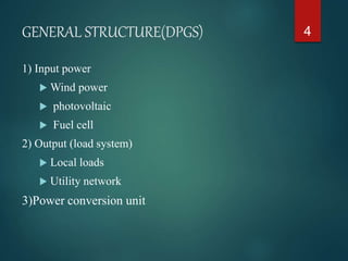
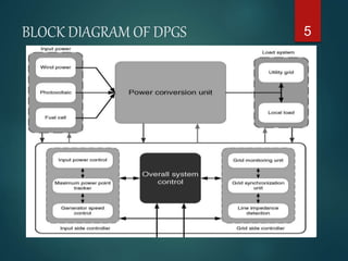
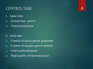
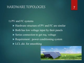
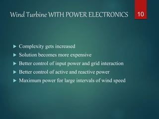
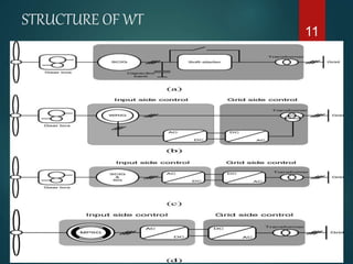
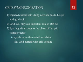
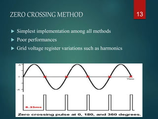
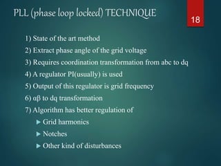
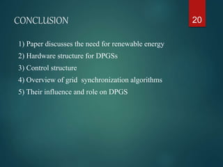
OVERVIEW OF GRID STRUCTURE AND
SYNCHRONIZATION FOR DISTRIBUTED POWER
GENERATION SYSTEMS
1
Presented by:
MRINAL MAYANK
INTRODUCTION
 Fossil fuel main energy supplier for world
economy
 Cause of environmental problems
 Forced mankind to look for alternative resources
 Grid instability and outages due to increasing
demand
 More energy with clean technologies required
 Synchronization plays important role
2
WORLD energy SCENARIO
 Exponential growth in PV energy
 GOV. and utility companies supports schemes
related to PV
3
GENERAL STRUCTURE(DPGS)
1) Input power
 Wind power
 photovoltaic
 Fuel cell
2) Output (load system)
 Local loads
 Utility network
3)Power conversion unit
4
BLOCK DIAGRAM OF DPGS 5
CONTROL TASK
1. Input side:
a) Extract max. power
b) Natural protection
2. Grid side:
a) Control of active power generated
b) Control of reactive power transfer
c) Grid synchronization
d) High quality of injected power
6
HARDWARE TOPOLOGIES
1) PV and FC systems
 Hardware structure of PV and FC are similar
 Both has low voltage input by their panels
 Series connection to get req. voltage
 Requirement : power conditioning system
 LCL ckt. for smoothing
7
PV SYSTEM STRUCTURE 8
Wind Turbine without power electronics
DEVICES
 Based on squirrel-cage induction generator
 Soft starter to reduce the inrush currents
 Capacitor bank for compensation of reactive
power
9
Wind Turbine WITH POWER ELECTRONICS
 Complexity gets increased
 Solution becomes more expensive
 Better control of input power and grid interaction
 Better control of active and reactive power
 Maximum power for large intervals of wind speed
10
STRUCTURE OF WT
11
GRID SYNCHRONIZATION
1) Injected current into utility network has to be syn
with grid volt
2) Grid syn. plays an important role in DPGSs
3) Syn. algorithm outputs the phase of the grid
voltage vector
 synchronize the control variables.
Eg. Grid current with grid voltage
12
ZERO CROSSING METHOD
 Simplest implementation among all methods
 Poor performances
 Grid voltage register variations such as harmonics
13
REFERENCE FRAME
1) Synchronous reference frame
a) dq control
b) Rotates synchronously with grid voltage
c) Variables becomes DC values
2) Stationary reference frame control
a) PR controller is used
b) abc to αβ module
3) Natural frame control
a) Dead-beat controller is used
b) abc has individual controller for each grid current
14
FILTERING OF GRID VOLTAGES
1) Done in different reference frames such as dq or αβ
2) Improved performance
3) Difficulty in extracting phase angle
 Grid variations
 Faults
4) Delay is introduced
15
16
Filtering on dq synchronous rotating reference frame
17
Filtering on αβ reference frame
PLL (phase loop locked) TECHNIQUE
1) State of the art method
2) Extract phase angle of the grid voltage
3) Requires coordination transformation from abc to dq
4) A regulator PI(usually) is used
5) Output of this regulator is grid frequency
6) αβ to dq transformation
7) Algorithm has better regulation of
 Grid harmonics
 Notches
 Other kind of disturbances
18
19
CONCLUSION
1) Paper discusses the need for renewable energy
2) Hardware structure for DPGSs
3) Control structure
4) Overview of grid synchronization algorithms
5) Their influence and role on DPGS
20
21
THANK YOU
Thank you

overview of grid structure and synchronization for distributed power generation systems

  • 1.
    OVERVIEW OF GRIDSTRUCTURE AND SYNCHRONIZATION FOR DISTRIBUTED POWER GENERATION SYSTEMS 1 Presented by: MRINAL MAYANK
  • 2.
    INTRODUCTION  Fossil fuelmain energy supplier for world economy  Cause of environmental problems  Forced mankind to look for alternative resources  Grid instability and outages due to increasing demand  More energy with clean technologies required  Synchronization plays important role 2
  • 3.
    WORLD energy SCENARIO Exponential growth in PV energy  GOV. and utility companies supports schemes related to PV 3
  • 4.
    GENERAL STRUCTURE(DPGS) 1) Inputpower  Wind power  photovoltaic  Fuel cell 2) Output (load system)  Local loads  Utility network 3)Power conversion unit 4
  • 5.
  • 6.
    CONTROL TASK 1. Inputside: a) Extract max. power b) Natural protection 2. Grid side: a) Control of active power generated b) Control of reactive power transfer c) Grid synchronization d) High quality of injected power 6
  • 7.
    HARDWARE TOPOLOGIES 1) PVand FC systems  Hardware structure of PV and FC are similar  Both has low voltage input by their panels  Series connection to get req. voltage  Requirement : power conditioning system  LCL ckt. for smoothing 7
  • 8.
  • 9.
    Wind Turbine withoutpower electronics DEVICES  Based on squirrel-cage induction generator  Soft starter to reduce the inrush currents  Capacitor bank for compensation of reactive power 9
  • 10.
    Wind Turbine WITHPOWER ELECTRONICS  Complexity gets increased  Solution becomes more expensive  Better control of input power and grid interaction  Better control of active and reactive power  Maximum power for large intervals of wind speed 10
  • 11.
  • 12.
    GRID SYNCHRONIZATION 1) Injectedcurrent into utility network has to be syn with grid volt 2) Grid syn. plays an important role in DPGSs 3) Syn. algorithm outputs the phase of the grid voltage vector  synchronize the control variables. Eg. Grid current with grid voltage 12
  • 13.
    ZERO CROSSING METHOD Simplest implementation among all methods  Poor performances  Grid voltage register variations such as harmonics 13
  • 14.
    REFERENCE FRAME 1) Synchronousreference frame a) dq control b) Rotates synchronously with grid voltage c) Variables becomes DC values 2) Stationary reference frame control a) PR controller is used b) abc to αβ module 3) Natural frame control a) Dead-beat controller is used b) abc has individual controller for each grid current 14
  • 15.
    FILTERING OF GRIDVOLTAGES 1) Done in different reference frames such as dq or αβ 2) Improved performance 3) Difficulty in extracting phase angle  Grid variations  Faults 4) Delay is introduced 15
  • 16.
    16 Filtering on dqsynchronous rotating reference frame
  • 17.
    17 Filtering on αβreference frame
  • 18.
    PLL (phase looplocked) TECHNIQUE 1) State of the art method 2) Extract phase angle of the grid voltage 3) Requires coordination transformation from abc to dq 4) A regulator PI(usually) is used 5) Output of this regulator is grid frequency 6) αβ to dq transformation 7) Algorithm has better regulation of  Grid harmonics  Notches  Other kind of disturbances 18
  • 19.
  • 20.
    CONCLUSION 1) Paper discussesthe need for renewable energy 2) Hardware structure for DPGSs 3) Control structure 4) Overview of grid synchronization algorithms 5) Their influence and role on DPGS 20
  • 21.