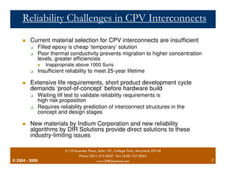
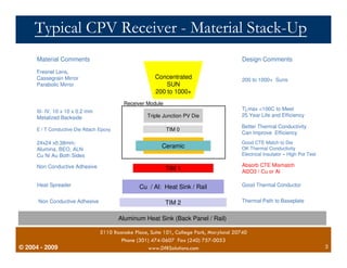
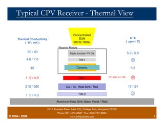
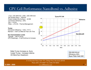
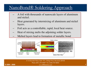
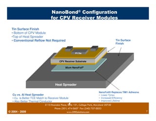
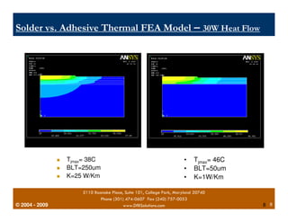
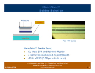
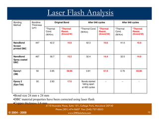
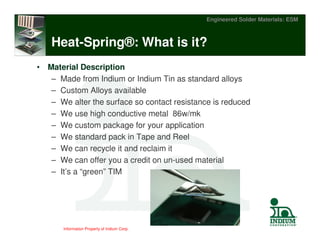
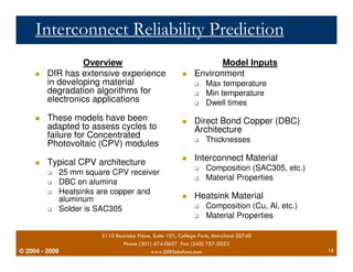
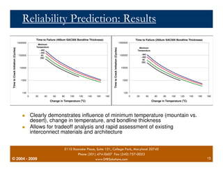
Ensuring and Predicting the 
Reliability of Concentrated 
Photovoltaics (CPV): Interconnect 
Structures 
© 2004 - 2009 
Greg Caswell and Craig Hillman 
DfR Solutions 
February 15, 2010 
Jordan Ross 
Indium Corporation
Reliability Challenges in CPV Interconnects 
 Current material selection for CPV interconnects are insufficient 
 Filled epoxy is cheap ‘temporary’ solution 
 Poor thermal conductivity prevents migration to higher concentration 
levels, greater efficiencies 
 Insufficient reliability to meet 25-year lifetime 
 Extensive life requirements, short product development cycle 
demands ‘proof-of-concept’ before hardware build 
 Waiting till test to validate reliability requirements is 
high risk proposition 
 Requires reliability prediction of interconnect structures in the 
concept and design stages 
 New materials by Indium Corporation and new reliability 
algorithms by DfR Solutions provide direct solutions to these 
industry-limiting issues 
© 2004 - 2007 
 Inappropriate above 1000 Suns 
5110 Roanoke Place, Suite 101, College Park, Maryland 20740 
Phone (301) 474-0607 Fax (240) 757-0053 
2009 www.DfRSolutions.com 2
Typical CPV Receiver - Material Stack-Up 
Material Comments 
Fresnel Lens, 
Cassegrain Mirror 
Parabolic Mirror 
III- IV, 10 x 10 x 0.2 mm 
Metalized Backside 
E / T Conductive Die Attach Epoxy 
24x24 x0.38mm: 
Alumina, BEO, ALN 
Cu Ni Au Both Sides 
Non Conductive Adhesive 
Heat Spreader 
Non Conductive Adhesive 
© 2004 - 2007 
Concentrated 
SUN 
200 to 1000+ 
Receiver Module 
Triple Junction PV Die 
TIM 0 
Ceramic 
TIM 1 
Cu / Al: Heat Sink / Rail 
TIM 2 
Aluminum Heat Sink (Back Panel / Rail) 
Design Comments 
200 to 1000+ Suns 
Tj,max 100C to Meet 
25 Year Life and Efficiency 
Better Thermal Conductivity 
Can Improve Efficiency 
Good CTE Match to Die 
OK Thermal Conductivity 
Electrical Insulator – High Pot Test 
Absorb CTE Mismatch 
Al2O3 / Cu or Al 
Good Thermal Conductor 
Thermal Path to Baseplate 
5110 Roanoke Place, Suite 101, College Park, Maryland 20740 
Phone (301) 474-0607 Fax (240) 757-0053 
2009 www.DfRSolutions.com 3
Typical CPV Receiver - Thermal View 
Thermal Conductivity 
( W / mK ) 
4.0 / 7.0 
1 .0 / 4.0 
210 / 360 
1 .0 / 4.0 
© 2004 - 2007 
Concentrated 
SUN 
200 to 1000+ 
Receiver Module 
Triple Junction PV Die 
TIM 0 
Ceramic 
TIM 1 
Cu / Al: Heat Sink / Rail 
TIM 2 
Aluminum Heat Sink (Back Panel / Rail) 
TC -40C to 110C 
5110 Roanoke Place, Suite 101, College Park, Maryland 20740 
Phone (301) 474-0607 Fax (240) 757-0053 
50 / 60 
46 
CTE 
( ppm / C) 
5.0 / 6.0 
 
5.5 
 
16 / 24 
 
2009 www.DfRSolutions.com 4
CPV Cell Performance NanoBond vs. Adhesive 
Delta Tj,max Increase vs. Suns 
•Lower Tj,max - Increase Lifetime 
•Or More Sun Headroom 
© 2004 - 2007 
5110 Roanoke Place, Suite 101, College Park, Maryland 20740 
Phone (301) 474-0607 Fax (240) 757-0053 
Adhesive 
NanoBond® 
DNI 850 W/m2 
Efficiency 35% 
Base Plate Held 28C 
2009 www.DfRSolutions.com 5 
5 
1 Sun = 85 mW/mm2 x 500 = 425 mW/mm2 
Die Surface Area = 100mm2 
Power Incident Die Surface = 42.5W 
Conversion Efficiency = 35% 
Pdc = 14.9 W 
Pdiss = 27.6 W – Thermal Management 
Tj,max 
Conversion Efficiency ~ 0.5% / 10°C 
Maintain  100°C to Meet 25 Year Life Time 
Sun Concentration Levels 
Typically ~ 500 X (Suns) 
CPV Roadmaps – X will Continue to Increase
NanoBond® Soldering Approach 
– A foil with thousands of nanoscale layers of aluminum 
– Heat generated by intermixing of aluminum and nickel 
– Foil acts as a controllable, rapid, local heat source. 
– Heat of mixing melts the adjoining solder layers. 
– Melted layers lead to formation of metallic bond 
© 2004 - 2007 
and nickel. 
5110 Roanoke Place, Suite 101, College Park, Maryland 20740 
Phone (301) 474-0607 Fax (240) 757-0053 
layers. 
2009 www.DfRSolutions.com 6
Tin Surface Finish 
• Bottom of CPV Module 
•Top of Heat Spreader 
• Conventional Reflow Not Required 
Cu vs. Al Heat Spreader 
• Cu is Better TCE Match to Receiver Module 
• Also Better Thermal Conductor 
© 2004 - 2007 
NanoBond® Configuration 
for CPV Receiver Modules 
PV Die 
CPV Receiver Substrate 
80um NanoFoil® 
Heat Spreader 
NanoFoil® Replaces TIM1 Adhesive 
• Lower Tjmax 
• Increased Efficiency 
• Improved Lifetime 
5110 Roanoke Place, Suite 101, College Park, Maryland 20740 
Phone (301) 474-0607 Fax (240) 757-0053 
Tin Surface 
Finish 
2009 www.DfRSolutions.com 7
Solder vs. Adhesive Thermal FEA Model – 30W Heat Flow 
© 2004 - 2007 
 Tjmax= 38C 
 BLT=250um 
 K=25 W/Km 
• Tjmax= 46C 
• BLT=50um 
• K=1W/Km 
5110 Roanoke Place, Suite 101, College Park, Maryland 20740 
Phone (301) 474-0607 Fax (240) 757-0053 
2009 www.DfRSolutions.com 8 
8
© 2004 - 2007 
NanoBond® 
Solder Solution 
Pressure 
Heat Sink 
Solder 
NanoBond® Solder Bond 
Post 1000 Cycles 
 Cu Heat Sink and Receiver Module 
 1000 cycles completed, no degradation 
 -25 to +125C (8.5C per minute ramp) 
5110 Roanoke Place, Suite 101, College Park, Maryland 20740 
Phone (301) 474-0607 Fax (240) 757-0053 
2009 www.DfRSolutions.com 9 
9
Original Bond After 540 cycles After 940 cycles 
*Thermal 
Resist. 
(Kmm2/W) 
*Thermal 
Resist. 
(Kmm2/W) 
*Thermal 
Cond. 
(W/Km) 
Bondline 
Thickness 
(μm) 
Bonding 
Method 
NanoBond 447 42.2 10.6 
10.9 
Screen 
printed DBC 
NanoBond 467 30.7 14.4 
14.6 
Spray coated 
DBC 
*Thermal Cond. 
(W/Km) 
42.3 
32.4 
*Thermal 
Cond. 
(W/Km) 
41.0 
32.0 
*Thermal 
Resist. 
(Kmm2/W) 
10.6 
15.2 
Epoxy1 50 0.85 58.96 0.81 61.9 0.76 65.86 
(3M) 
Epoxy 2 50 2.83 17.6 
(Epo-Tek) 
•Bond size 24 mm x 24 mm 
•DBC material properties have been corrected using laser flash 
•Copper thickness 1.6 mm 
© 2004 - 2007 
Laser Flash Analysis 
Results 
Bonds started - -- - 
falling apart 
at 400 cycles 
5110 Roanoke Place, Suite 101, College Park, Maryland 20740 
Phone (301) 474-0607 Fax (240) 757-0053 
2009 www.DfRSolutions.com 10
Information Property of Indium Corp. 
Engineered Solder Materials: ESM 
Heat-Spring®: What is it? 
• Material Description 
– Made from Indium or Indium Tin as standard alloys 
– Custom Alloys available 
– We alter the surface so contact resistance is reduced 
– We use high conductive metal 86w/mk 
– We custom package for your application 
– We standard pack in Tape and Reel 
– We can recycle it and reclaim it 
– We can offer you a credit on un-used material 
– It’s a “green” TIM
Information Property of Indium Corp. 
Engineered Solder Materials: ESM 
Soft Metal TIM Attributes 
• High thermal conductivity 
86W/mK 
– Low bulk resistance— 
insensitive to BLT 
– Heat spreading 
• Conformability 
– Plastic deformation provides 
low contact resistance path, 
especially after time zero 
(burn-in period) 
– Inherent gap filling for co-planarity 
issues: 
– HSD: +/- .003” 
– HSG: +/- .010” 
– Complies with CTE 
mismatch 
• Stability/ Advantages 
– No out-gassing 
– No bake-out or pump-out 
– Easy to handle 
– Reclaimable/ recyclable 
• Thickness 
– HSD pattern, minimum 
thickness before Patented 
Heat-Spring Process is 
75um, after the HSD 
process thickness will 
increase 75um. 
– HSG pattern, minimum 
thickness before Patented 
Heat-Spring process is 
150um, after HSG is 300um 
– HSG pattern can be applied 
to a 250um preform and 
after HSG process will be 
500um thick. 
– Max Thickness is well over 
.25 inches if necessary.
Information Property of Indium Corp. 
Engineered Solder Materials: ESM 
Stack-up Pictorial 
TIM1: Indium Solder Preforms, or 
conceptual Liquid Metal. 
TIM1.5: Heat-Spring®, Liquid Metal 
TIM2: Heat-Spring®, Liquid Metal 
Burn-in and Test: Heat-Spring® and 
Aluminum Indium Clad preforms.
Interconnect Reliability Prediction 
 DfR has extensive experience 
in developing material 
degradation algorithms for 
electronics applications 
 These models have been 
adapted to assess cycles to 
failure for Concentrated 
Photovoltaic (CPV) modules 
 Typical CPV architecture 
 25 mm square CPV receiver 
 DBC on alumina 
 Heatsinks are copper and 
aluminum 
 Solder is SAC305 
© 2004 - 2007 
Overview 
Model Inputs 
 Environment 
 Max temperature 
 Min temperature 
 Dwell times 
 Direct Bond Copper (DBC) 
Architecture 
 Thicknesses 
 Interconnect Material 
 Composition (SAC305, etc.) 
 Material Properties 
 Heatsink Material 
 Composition (Cu, Al, etc.) 
 Material Properties 
5110 Roanoke Place, Suite 101, College Park, Maryland 20740 
Phone (301) 474-0607 Fax (240) 757-0053 
2009 www.DfRSolutions.com 14
Reliability Prediction: Results 
1000000 
100000 
10000 
1000 
Time to Failure (400um SAC305 Bondline Thickness) 
1000000 
100000 
10000 
1000 
Time to Failure (250um SAC305 Bondline Thickness) 
 Clearly demonstrates influence of minimum temperature (mountain vs. 
desert), change in temperature, and bondline thickness 
 Allows for tradeoff analysis and rapid assessment of existing 
interconnect materials and architecture 
© 2004 - 2007 
5110 Roanoke Place, Suite 101, College Park, Maryland 20740 
Phone (301) 474-0607 Fax (240) 757-0053 
2009 www.DfRSolutions.com 15 
100 
0 20 40 60 80 100 120 140 160 180 
Change in Temperature (oC) 
Time to Crack Initiation (Cycles) 
Minimum 
Temperature 
- 40C 
- 25C 
0C 
25C 
100 
0 20 40 60 80 100 120 140 160 180 
Change in Temperature (oC) 
Time to Crack Initiation (Cycles) 
Minimum 
Temperature 
- 40C 
- 25C 
0C 
25C
Summary 
 DfR and Indium provide a turn-key solution for the 
reliability assurance of CPV modules 
 New materials and technology for radical 
improvement in interconnect robustness 
 Commercially available NanoBonding and Heat Spring 
 Interconnect reliability algorithm adapted to assess 
cycles to failure for Concentrated Photovoltaic 
(CPV) modules 
© 2004 - 2007 
5110 Roanoke Place, Suite 101, College Park, Maryland 20740 
Phone (301) 474-0607 Fax (240) 757-0053 
2009 www.DfRSolutions.com 16

Ensuring and predicting the reliability of cpv

  • 1.
    Ensuring and Predictingthe Reliability of Concentrated Photovoltaics (CPV): Interconnect Structures © 2004 - 2009 Greg Caswell and Craig Hillman DfR Solutions February 15, 2010 Jordan Ross Indium Corporation
  • 2.
    Reliability Challenges inCPV Interconnects Current material selection for CPV interconnects are insufficient Filled epoxy is cheap ‘temporary’ solution Poor thermal conductivity prevents migration to higher concentration levels, greater efficiencies Insufficient reliability to meet 25-year lifetime Extensive life requirements, short product development cycle demands ‘proof-of-concept’ before hardware build Waiting till test to validate reliability requirements is high risk proposition Requires reliability prediction of interconnect structures in the concept and design stages New materials by Indium Corporation and new reliability algorithms by DfR Solutions provide direct solutions to these industry-limiting issues © 2004 - 2007 Inappropriate above 1000 Suns 5110 Roanoke Place, Suite 101, College Park, Maryland 20740 Phone (301) 474-0607 Fax (240) 757-0053 2009 www.DfRSolutions.com 2
  • 3.
    Typical CPV Receiver- Material Stack-Up Material Comments Fresnel Lens, Cassegrain Mirror Parabolic Mirror III- IV, 10 x 10 x 0.2 mm Metalized Backside E / T Conductive Die Attach Epoxy 24x24 x0.38mm: Alumina, BEO, ALN Cu Ni Au Both Sides Non Conductive Adhesive Heat Spreader Non Conductive Adhesive © 2004 - 2007 Concentrated SUN 200 to 1000+ Receiver Module Triple Junction PV Die TIM 0 Ceramic TIM 1 Cu / Al: Heat Sink / Rail TIM 2 Aluminum Heat Sink (Back Panel / Rail) Design Comments 200 to 1000+ Suns Tj,max 100C to Meet 25 Year Life and Efficiency Better Thermal Conductivity Can Improve Efficiency Good CTE Match to Die OK Thermal Conductivity Electrical Insulator – High Pot Test Absorb CTE Mismatch Al2O3 / Cu or Al Good Thermal Conductor Thermal Path to Baseplate 5110 Roanoke Place, Suite 101, College Park, Maryland 20740 Phone (301) 474-0607 Fax (240) 757-0053 2009 www.DfRSolutions.com 3
  • 4.
    Typical CPV Receiver- Thermal View Thermal Conductivity ( W / mK ) 4.0 / 7.0 1 .0 / 4.0 210 / 360 1 .0 / 4.0 © 2004 - 2007 Concentrated SUN 200 to 1000+ Receiver Module Triple Junction PV Die TIM 0 Ceramic TIM 1 Cu / Al: Heat Sink / Rail TIM 2 Aluminum Heat Sink (Back Panel / Rail) TC -40C to 110C 5110 Roanoke Place, Suite 101, College Park, Maryland 20740 Phone (301) 474-0607 Fax (240) 757-0053 50 / 60 46 CTE ( ppm / C) 5.0 / 6.0 5.5 16 / 24 2009 www.DfRSolutions.com 4
  • 5.
    CPV Cell PerformanceNanoBond vs. Adhesive Delta Tj,max Increase vs. Suns •Lower Tj,max - Increase Lifetime •Or More Sun Headroom © 2004 - 2007 5110 Roanoke Place, Suite 101, College Park, Maryland 20740 Phone (301) 474-0607 Fax (240) 757-0053 Adhesive NanoBond® DNI 850 W/m2 Efficiency 35% Base Plate Held 28C 2009 www.DfRSolutions.com 5 5 1 Sun = 85 mW/mm2 x 500 = 425 mW/mm2 Die Surface Area = 100mm2 Power Incident Die Surface = 42.5W Conversion Efficiency = 35% Pdc = 14.9 W Pdiss = 27.6 W – Thermal Management Tj,max Conversion Efficiency ~ 0.5% / 10°C Maintain 100°C to Meet 25 Year Life Time Sun Concentration Levels Typically ~ 500 X (Suns) CPV Roadmaps – X will Continue to Increase
  • 6.
    NanoBond® Soldering Approach – A foil with thousands of nanoscale layers of aluminum – Heat generated by intermixing of aluminum and nickel – Foil acts as a controllable, rapid, local heat source. – Heat of mixing melts the adjoining solder layers. – Melted layers lead to formation of metallic bond © 2004 - 2007 and nickel. 5110 Roanoke Place, Suite 101, College Park, Maryland 20740 Phone (301) 474-0607 Fax (240) 757-0053 layers. 2009 www.DfRSolutions.com 6
  • 7.
    Tin Surface Finish • Bottom of CPV Module •Top of Heat Spreader • Conventional Reflow Not Required Cu vs. Al Heat Spreader • Cu is Better TCE Match to Receiver Module • Also Better Thermal Conductor © 2004 - 2007 NanoBond® Configuration for CPV Receiver Modules PV Die CPV Receiver Substrate 80um NanoFoil® Heat Spreader NanoFoil® Replaces TIM1 Adhesive • Lower Tjmax • Increased Efficiency • Improved Lifetime 5110 Roanoke Place, Suite 101, College Park, Maryland 20740 Phone (301) 474-0607 Fax (240) 757-0053 Tin Surface Finish 2009 www.DfRSolutions.com 7
  • 8.
    Solder vs. AdhesiveThermal FEA Model – 30W Heat Flow © 2004 - 2007 Tjmax= 38C BLT=250um K=25 W/Km • Tjmax= 46C • BLT=50um • K=1W/Km 5110 Roanoke Place, Suite 101, College Park, Maryland 20740 Phone (301) 474-0607 Fax (240) 757-0053 2009 www.DfRSolutions.com 8 8
  • 9.
    © 2004 -2007 NanoBond® Solder Solution Pressure Heat Sink Solder NanoBond® Solder Bond Post 1000 Cycles Cu Heat Sink and Receiver Module 1000 cycles completed, no degradation -25 to +125C (8.5C per minute ramp) 5110 Roanoke Place, Suite 101, College Park, Maryland 20740 Phone (301) 474-0607 Fax (240) 757-0053 2009 www.DfRSolutions.com 9 9
  • 10.
    Original Bond After540 cycles After 940 cycles *Thermal Resist. (Kmm2/W) *Thermal Resist. (Kmm2/W) *Thermal Cond. (W/Km) Bondline Thickness (μm) Bonding Method NanoBond 447 42.2 10.6 10.9 Screen printed DBC NanoBond 467 30.7 14.4 14.6 Spray coated DBC *Thermal Cond. (W/Km) 42.3 32.4 *Thermal Cond. (W/Km) 41.0 32.0 *Thermal Resist. (Kmm2/W) 10.6 15.2 Epoxy1 50 0.85 58.96 0.81 61.9 0.76 65.86 (3M) Epoxy 2 50 2.83 17.6 (Epo-Tek) •Bond size 24 mm x 24 mm •DBC material properties have been corrected using laser flash •Copper thickness 1.6 mm © 2004 - 2007 Laser Flash Analysis Results Bonds started - -- - falling apart at 400 cycles 5110 Roanoke Place, Suite 101, College Park, Maryland 20740 Phone (301) 474-0607 Fax (240) 757-0053 2009 www.DfRSolutions.com 10
  • 11.
    Information Property ofIndium Corp. Engineered Solder Materials: ESM Heat-Spring®: What is it? • Material Description – Made from Indium or Indium Tin as standard alloys – Custom Alloys available – We alter the surface so contact resistance is reduced – We use high conductive metal 86w/mk – We custom package for your application – We standard pack in Tape and Reel – We can recycle it and reclaim it – We can offer you a credit on un-used material – It’s a “green” TIM
  • 12.
    Information Property ofIndium Corp. Engineered Solder Materials: ESM Soft Metal TIM Attributes • High thermal conductivity 86W/mK – Low bulk resistance— insensitive to BLT – Heat spreading • Conformability – Plastic deformation provides low contact resistance path, especially after time zero (burn-in period) – Inherent gap filling for co-planarity issues: – HSD: +/- .003” – HSG: +/- .010” – Complies with CTE mismatch • Stability/ Advantages – No out-gassing – No bake-out or pump-out – Easy to handle – Reclaimable/ recyclable • Thickness – HSD pattern, minimum thickness before Patented Heat-Spring Process is 75um, after the HSD process thickness will increase 75um. – HSG pattern, minimum thickness before Patented Heat-Spring process is 150um, after HSG is 300um – HSG pattern can be applied to a 250um preform and after HSG process will be 500um thick. – Max Thickness is well over .25 inches if necessary.
  • 13.
    Information Property ofIndium Corp. Engineered Solder Materials: ESM Stack-up Pictorial TIM1: Indium Solder Preforms, or conceptual Liquid Metal. TIM1.5: Heat-Spring®, Liquid Metal TIM2: Heat-Spring®, Liquid Metal Burn-in and Test: Heat-Spring® and Aluminum Indium Clad preforms.
  • 14.
    Interconnect Reliability Prediction DfR has extensive experience in developing material degradation algorithms for electronics applications These models have been adapted to assess cycles to failure for Concentrated Photovoltaic (CPV) modules Typical CPV architecture 25 mm square CPV receiver DBC on alumina Heatsinks are copper and aluminum Solder is SAC305 © 2004 - 2007 Overview Model Inputs Environment Max temperature Min temperature Dwell times Direct Bond Copper (DBC) Architecture Thicknesses Interconnect Material Composition (SAC305, etc.) Material Properties Heatsink Material Composition (Cu, Al, etc.) Material Properties 5110 Roanoke Place, Suite 101, College Park, Maryland 20740 Phone (301) 474-0607 Fax (240) 757-0053 2009 www.DfRSolutions.com 14
  • 15.
    Reliability Prediction: Results 1000000 100000 10000 1000 Time to Failure (400um SAC305 Bondline Thickness) 1000000 100000 10000 1000 Time to Failure (250um SAC305 Bondline Thickness) Clearly demonstrates influence of minimum temperature (mountain vs. desert), change in temperature, and bondline thickness Allows for tradeoff analysis and rapid assessment of existing interconnect materials and architecture © 2004 - 2007 5110 Roanoke Place, Suite 101, College Park, Maryland 20740 Phone (301) 474-0607 Fax (240) 757-0053 2009 www.DfRSolutions.com 15 100 0 20 40 60 80 100 120 140 160 180 Change in Temperature (oC) Time to Crack Initiation (Cycles) Minimum Temperature - 40C - 25C 0C 25C 100 0 20 40 60 80 100 120 140 160 180 Change in Temperature (oC) Time to Crack Initiation (Cycles) Minimum Temperature - 40C - 25C 0C 25C
  • 16.
    Summary DfRand Indium provide a turn-key solution for the reliability assurance of CPV modules New materials and technology for radical improvement in interconnect robustness Commercially available NanoBonding and Heat Spring Interconnect reliability algorithm adapted to assess cycles to failure for Concentrated Photovoltaic (CPV) modules © 2004 - 2007 5110 Roanoke Place, Suite 101, College Park, Maryland 20740 Phone (301) 474-0607 Fax (240) 757-0053 2009 www.DfRSolutions.com 16