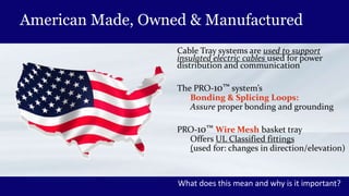
A SUBSIDARY OF VUTEC USA CORP
Gabe Vasquez – National Sales Manager
Since 1950 WIREMAID Has Been
A Leader in Design & Manufacturing of:
Wire Products
Guards for Lighting Fixtures & Fans
Founded on Long Island N.Y.
Manufactured in Coral Springs, Florida
American Made, Owned & Manufactured
Cable Tray systems are used to support
insulated electric cables used for power
distribution and communication
The PRO-10™ system’s
Bonding & Splicing Loops:
Assure proper bonding and grounding
PRO-10™ Wire Mesh basket tray
Offers UL Classified fittings
(used for: changes in direction/elevation)
What does this mean and why is it important?
Eco-Friendly, Lightweight and Easy to Install
We use eco-friendly recyclable materials
Designed for Ease of Installation
Reduces installation time up to 50%
Cuts down on injuries
Systems can be used in both
Commercial/Industrial environments
Ratchet CM99
WIREMAID (Pro-10™)
Unique Cable Tray System
NEC 392.5 Compliant Fittings
Used for bonding & grounding
and for changes in direction
No need for bonding jumpers
No additional hardware needed
Full UL Classification®
For ground conductor
CABLE-MGR ® PRO-10
*U.S. Patent No. 7,546,987 No Cutting , Bending or Field Modifications
First Things First
What Are Cable Trays?
An assembly of units/sections with associated
fittings that form a rigid structural system to
securely fasten or support cables.
Think of a roadway bridge that supports traffic!
The Advantages of WIREMAID PRO-10™
Cost & Space Savings
Safety (related) Savings
*Design & Engineering Cost Savings
Installation Cost and Time Savings
You Wont Break the Bank Using Our Product!
*Compared to conduit
Design & Construction
Made from cold rolled high strength
steel wire with pre-galvanized loops
(AISI type 304/316 stainless steel
are both available)
Designed for flexibility, safety & assembly
Eliminates need for cutting or bending
304 contains 18% chromium/8% nickel. 316 contains 16% chromium/10% nickel & 2% molybdenum added to resist corrosion
Codes & Standards
Electrical Equipment & Grounding
Cable Tray Systems must provide protection to:
Life & Property against faults caused by electrical disturbances
Lighting and failures which are part of the system
Failure for equipment connected to the system
To drain off excessive high voltages
Let’s look at basic Codes and Standards
What is (Electrical) Code?
The National Electrical Code (NEC)
Standard for Electrical Safety Installation of Electrical Wiring
Codifies (collects and classifies) the minimum
requirements for safe electrical installations
The NEC is not in itself a U.S. law
It is commonly mandated by state/local law
Local jurisdictions/code enforcement inspect for compliance
NEC – National Electric Code (NFPA-70)
Codifies the requirements for safe electrical installations
• Started in 1897
• Published and updated every 3 years
• Deals solely with Electrical Safety
Codes
ComplianceData/Stats
Technology
Codes incorporate
new technology
and data
Adopted codes are
enforced via
inspections
and penalties
Data & Statistics
fuel needed
innovation
and policy
New Technology
addresses
deficiencies and
R&D
Building Safety Codes
Specify Construction Minimum Standards
Needed to protect public health, safety
and general welfare
Generally applied to architects, engineers
and constructors
IBC
International Building Code
Code Violation
Fire Safety Codes
National Fire Protection Association (NFPA 70)
Adopted in all 50 states
Code covers installation of electrical conductors,
equipment and raceways
Includes both public and private buildings
Codes & Standards
OSHA Safety Codes
Personnel Safety
Underwriter Codes
Insurance Codes
Codes Developed for Safety!
Our Products Comply With The Codes
Our Product Also Complies With:
Telecommunications Cabling Standards
General Cabling Standards (for Communications)
Networking Performance Standards
942 Data Center Standard
Telecommunications Cabling
“Overhead cable trays should be
suspended from the deck above
the ceiling”
“Under floor cable trays may be
installed in multiple layers to
provide additional capacity”
NEC 392.5
(E) Fittings
“Cable trays shall include
fittings or other suitable
means for changes in
direction and elevation runs”.
Why Are These Important To Know?
So you can communicate
with your client should
the topics come up in
conversation.
Brief Description of Cable Trays
A Mechanical Support (Management) System
Used for:
Insulated electrical cables in:
Power Distribution/Communications
As an alternative to open wiring (electrical conduit systems)
Made of galvanized steel or stainless steel
They are NOT Raceways
(An enclosed channel of metal or non metallic design)
Trays can be made of aluminum or reinforced glass fiber but are combustible!
M.E.2 Cable Trays
Standard Cost Effective System!
Strong & Rigid Ø.187 zinc-plated steel wire
Welded in a 2” X 4” grid
Available in 7’ of 10’ lengths
(configured at the installation site)
2” or 4” deep trays
6”-8”-12”-18”-24” widths offer a variety of channel routing
Open grid design prevents dirt dust build-up found in closed cable trays
Ø = DiameterActs as a continuous ground conductor; no grounding splices
Straight Section
M.E.2 Cable Trays
Changes in direction are made with cutting
and bending the trays to meet needs.
Can be mounted on walls, post,
ceilings or installed under raised flooring.
Metal tray dividers are
available for cable separation.
Field Connections
• khhkihki
Splice Washer Kit
05-2-600726
Splicing
3 PC Washer SPL Kit Available #05-2-600726
UL Approved as equipment ground conductor
Used as a splice option and in the configuration
of tray bends as well as connecting the tray supports
Cable Tray Weight, Load & Fill Chart
Dimensions Tray Weight *Max # of cables Load Capacity Load capacity
D x W x L (in.) (lbs) @ 50% fill ratio Over a 5' span (lbs/ft) over a 10' span (lbs./ft)
2 x 6 x 84 6.94 130 27 14
2 x 8 x 84 7.91 174 29 16
2 x 12 x 84 9.85 260 34 19
2 x 18 x 84 12.83 394 43 22
2 x 24 x 84 15.74 527 52 23
2 x 6 120 9.92 130 27 14
2 x 8 120 11.12 174 29 16
3 x 12 x 120 14.13 260 37 19
2 18 x 120 18.33 394 43 22
2 x 24 120 22.48 527 52 23
4 x 6 84 7.59 253 35 17
4 x 8 x 84 8.6 331 48 25
4 x 12 x 94 10.57 496 52 28
4 x 18 x 84 1.52 751 68 31
4 x 24 x 84 16.41 98 69 36
4 x 6 x 120 10.84 253 35 17
4 x 8 x 120 12.28 331 48 25
4 x 12 x 120 16 496 52 28
4 x 18 x 120 19.31 751 68 31
4 x 24 x 120 23.45 998 69 36
*Based on a 50% fill or 4 UTP CAT 6 cable (O.D.21”,@ .33 lbs./ft.)
Features & Benefits
Change routing elevation by cutting side wires and bending
Custom shorten 7’ or 10’ straight sections at installation site
Rigid Steel construction – Made in the USA
Factory Fabricated – Saves Time & Saves Money
PRO-10 Cable Trays
Lightweight Mesh Design Solution for Fiber Optic Cabling
Minimizes cable sagging/dropping!
Available in 2 wire diameter choices to
accommodate various cable tray load capacities
CM10 (Ø.120)
CM20 (Ø.187)
Widths of: 6”, 8”, 12”, 18” or 24”
Lengths of: 1’, 2’, 5’, 8’, or 10’
Depths of: 2”, 4”, or 6”
Ø = Diameter
PRO-10 Cable Trays
No Cutting or Bending required
CM20 Standard grid pattern of 2” X 4”
UL-Classified & Powder Coated
CM30 is the heaviest of the PRO-10 cable trays
Provide optimum support for heavy weight
cable situations
Ø = Diameter
PRO-10 ZF® Zink Whisker Free
Stainless Steel
Zink Whisker Free
Durable Powder Coat Finish
Contact Points and Hardware
UL Bonding & Splicing Built in
Reduces Installation Time by 50% or More!
What Are Zinc Whiskers?
Tiny growths
These form on the surfaces of objects
that are electroplated, or galvanized,
with zinc.
When present on circuit boards:
Can cause short circuits
that are difficult to diagnose.
The frequent movement of air and cables being installed or
removed from the tray will easily dislodge the tiny filaments
Particles disintegrate when a short circuit occurs
To Avoid Zinc Whiskers
Products should be:
Stainless Steel
Powder –Coated Finish
The Bottom Line!
Whiskers can grow on ANY
Zinc Coated Surface
That includes Cadmium Coated
Surface/Hardware
SOLUTION: A Hybrid cold-
rolled steel with stainless steel
loops and powder coating
Stainless Bonding Points Powder Coated Steel
A Better Solution: Hybrid Product – Powder Coated / Stainless Bonding & Hardware
CABLE-MGR® Meets The Challenge
and Goes Beyond!
PRO-10® A Closer Look
Requires NO bending or cutting
Ready–made 4-Way, “T” and “L” shaped junctions, Reducers,
Elevations and Angles
Acts as a continuous ground conductor no grounding splices
Adapts to difficult architectural designs to accommodate
changes in direction and elevation of cable runs
Reduces installation time up to 50 percent
30 Degree Turn
PRO-10®
• Provides strength, rigidity without
additional hardware; has smooth edges
• Manufactured in an array of protective,
powder-coated, colored finishes to minimize corrosion
• Powder coating is standard finish
• Featured in light or heavy duty product styles
• All support hardware available
• Custom sizes available
Smooth Edges
NEC – Section 392.5 (B)
“Cable Trays shall not have sharp edges, burrs, or projections
that could damage the insulation or jackets of the wiring”.
Field cuts can cause loss of UL® Classification
UL Does NOT Approve Field Modified Parts
Product modified after leaving factory
may not comply with safety requirements
UL is unable to determine if product
continues to comply
Section 392.7 (A) Metallic Cable Trays
Along with 250.96 requires:
Cable tray systems that support
electrical conductors to be electrically
continuous.
Effectively bonded and grounded.
(Whether mechanically, continuous or
with isolated segments.)
Is losing your UL® listing worth it?
No Field Cutting Or Bending Required
Field modified tray systems may suffer loss of:
Load Performance
Electrical Performance*
Safety Performance
Any cutting/bending during installation may jeopardize UL™
classification and require re-inspection!
* Especially where the system functions as an equipment ground conductor
2011 NEC Article 392.60 (A)
“Metal cable trays containing only non-powder conductors shall be
electrically continuous through approved connections or the use of
bonding jumper not smaller than 10 AWG”
Wiremaid’s PRO-10™ cable tray system:
Is the ONLY product on the market with our unique
built in self bonding mechanism
Assures a UL Classified bond at the same time tray
sections and/or fittings are spliced together
Bonding/Splicing built into every part. The only hardware required is a common bolt and nut!
Bolt & Nut supplied with every tray
CABLE-MGR Tray Product Review
All Sizes of Tray’s and Junctions
are UL® Listed
Minimum of 5MM (.187) Wire for Strength
Made in the U.S.
Tray Depths & Widths
• Tray Widths = 6” - 8” – 12” – 18” – 24” and 36”
2”
6”
4”
CABLE-MGR Tray Lengths
Tray Lengths:
• 1’
• 2’
• 5’
• 8’
• 10’
CABLE-MGR Tray Product Review
Powder Coat Finishes (7)
Provides resistance, connectivity and controls surface friction
Our Hybrid ZF Product
is stainless and powder coated
Zinc Galvanized to prevent rusting
1 2 3 104 5 6
Custom Colors Available
Catalog Numbering System CM 20 Straight
Tray Width
• 6” = 06
• 8” = 08
• 12” = 12
• 18” = 18
• 24” = 24
• 36” = 36
Tray Depth
• 2” = 02
• 4” = 04
• 6” = 06
05 – 20
Tray Length
• 1’ = 01
• 2’ = 02
• 5’ = 05
• 8’ = 08
• 10’ = 10
1 2 3 104 5 6
CM 20
08 2 10 3
Powder Coating
CABLE-MGR Tray Fittings
Straight Sections
CABLE-MGR Tray Fittings
“T” Fittings
CABLE-MGR Tray Fittings
“L” Fittings
CABLE-MGR Tray Fittings
“4-Way” Fittings
CABLE-MGR Tray Fittings
Reducer
Available in standard configurations
with a grid pattern of 2” x 2”
Depth/Height of: 2” or 4”
(8” – 6” & 6” – 4” are standard)
Sections include interconnecting hardware. Custom colors available.
CM - 19
CABLE-MGR Tray Fittings
CM 20 Cross Sections
Available in 2”, 4” & 6”
CM 10 Cross Sections
Available in 2” & 4”
Elevation Change
Tray Extension Loop
Universal Loop Splice
Tray Extension Offset Loops
Used for installations where sections don’t meet
Loops bolt to existing loops on the tray
Will adjust up to 12” when attached
To adjust simply slide the cable trays, fittings or
offset loops to meet and then tighten the hex nuts
Additional Benefits of Cable-Mgr
Product Cost
Labor Time - Cutting, Bending, Polishing, Grounding
Installation Time – Extra Manpower
Cleanup Time (cuttings and shavings)
Possible on the job injuries (cost time & money)
Inspection Time (UL Classification)
Up Next: Ceiling Suspension Supports Systems
Pro – Cable Ceiling Suspension System
Support - Ceiling
Center Hanger
Available up to 24”
Accepts *Threaded Rod 1/4” (CM50)
CM 51 - 3/8 Threaded Rod Kit
*Threaded Rod Not Included
Ceiling Support
Available in 3’ 6’ and 10’ 18, 24, 36 Lengths
Colors to match trays
Can support multiple tray runs
Use vertically with L/C Brackets
Pre-Punched for up to ½” threaded rod
Support
C Bracket
Sizes – 6” 8” 12”
Used in Suspended, Wall and Underfloor Applications
Can be Combined with another C or L Bracket for
Multi-Layered Installations
Support
L Bracket
Available up to 12” widths
Can also be used in underfloor applications
Trapeze Support
Kit Installation Hardware
• CM52 (1/4”)
• Includes 1 support bracket
• 2 ¼” finned nuts
• 4 ¼ flat washers
• 4 ¼” nuts
• CM53 (3/8”)
Threaded rod not included
A Natural Replacement For
Threaded/Rod or Chain Systems
• Found on complex projects around the world!
• Simple to use, versatile
• Minimal installation time.
Y-Fit Fixings
Fasteners
Snap Hocks
Trapeze Hangers and
Loop-End Fixings
Underfloor Support
Pedestal Kit
Bridges full stanchion supports and
no side-loading floor systems
Included parts: 2 pedestal clamps and bridge support
Pedestal Clamp
Attaches to all sizes & shapes of stanchions
Raised Floor Support
Standard widths of: 4” “ 8” 12” 18” and 24”
Standard heights of: 4” and 6”
Supports can be custom manufactured to different widths and heights
So Now You Have The Trays!
What Else Do They Need?
Cable Tray Covers
Standard Widths
Between 6” – 36”
Length
59”
Used when physical covering of the
entire tray is needed
Available in multiple finishes
Part # 05-CM21 –(06 – 26)
Cable Tray Divider
5’ Lengths
2’ and 4” deep tray
Attaches with Washer SPL Kit Hardware
(provided)
Manufactured with a “Hemmed Edge” to
eliminate sharp edges
Dividers can be welded in at time of order
Solid Bottom
Powder Coated to provide a
smooth protective surface
Standard Widths 6” – 24”
Available in 59” lengths
Can be supplied pre-assembled
Other Accessories
Coupling Nuts
Finned Nuts
Flat Washers
Carriage Bolts
Ground Bolts
Beam Clamps
Split Bolts
Ratchet CM99
Patented Ground/Splice Loops
Simplify Installation and Bill of Materials
Wiremaid Factory Built Fittings
100% UL Classified Parts with NO Modification Needed
Simplified One Tool Installation - Guaranteed Consistency
Wall Mount Rack Support
Attaches Cable-Mgr to Racks
Fits all sizes of trays
Standard finish (black)
2” – 36”
Uni-strut for 18”, 24”, 36” tray
05-5702-xx
Other Accessories Include
• Waterfall and Tray
• Protective Steel Tubing
• Supplied as part of center support kit
• Extension Offset Loop
J-Tray – 22” or 48” long with powder coat finish.
High quality steel attachment to a variety of structures eliminates sagging or bending of cables.
Benefits
• No Field Cutting or Bending Required
• Bonding and Splicing Built in
• Large Load Tested Capacity
• Factory Fittings/Junctions Available
• Standard Powder Coat Finish
• Ready–Made 4-Way, “T” and “L” junctions
• PRO-10 ZF No Zink Whiskers
PRO-10™ “The One Tool System”
Visit On Line – WWW.Wiremaidusa.com
Thank You

Cable Mgr cable tray Introduction

  • 1.
    A SUBSIDARY OFVUTEC USA CORP Gabe Vasquez – National Sales Manager
  • 2.
    Since 1950 WIREMAIDHas Been A Leader in Design & Manufacturing of: Wire Products Guards for Lighting Fixtures & Fans Founded on Long Island N.Y. Manufactured in Coral Springs, Florida
  • 3.
    American Made, Owned& Manufactured Cable Tray systems are used to support insulated electric cables used for power distribution and communication The PRO-10™ system’s Bonding & Splicing Loops: Assure proper bonding and grounding PRO-10™ Wire Mesh basket tray Offers UL Classified fittings (used for: changes in direction/elevation) What does this mean and why is it important?
  • 4.
    Eco-Friendly, Lightweight andEasy to Install We use eco-friendly recyclable materials Designed for Ease of Installation Reduces installation time up to 50% Cuts down on injuries Systems can be used in both Commercial/Industrial environments Ratchet CM99
  • 5.
    WIREMAID (Pro-10™) Unique CableTray System NEC 392.5 Compliant Fittings Used for bonding & grounding and for changes in direction No need for bonding jumpers No additional hardware needed Full UL Classification® For ground conductor CABLE-MGR ® PRO-10 *U.S. Patent No. 7,546,987 No Cutting , Bending or Field Modifications
  • 6.
    First Things First WhatAre Cable Trays? An assembly of units/sections with associated fittings that form a rigid structural system to securely fasten or support cables. Think of a roadway bridge that supports traffic!
  • 7.
    The Advantages ofWIREMAID PRO-10™ Cost & Space Savings Safety (related) Savings *Design & Engineering Cost Savings Installation Cost and Time Savings You Wont Break the Bank Using Our Product! *Compared to conduit
  • 8.
    Design & Construction Madefrom cold rolled high strength steel wire with pre-galvanized loops (AISI type 304/316 stainless steel are both available) Designed for flexibility, safety & assembly Eliminates need for cutting or bending 304 contains 18% chromium/8% nickel. 316 contains 16% chromium/10% nickel & 2% molybdenum added to resist corrosion
  • 9.
  • 10.
    Electrical Equipment &Grounding Cable Tray Systems must provide protection to: Life & Property against faults caused by electrical disturbances Lighting and failures which are part of the system Failure for equipment connected to the system To drain off excessive high voltages Let’s look at basic Codes and Standards
  • 11.
    What is (Electrical)Code? The National Electrical Code (NEC) Standard for Electrical Safety Installation of Electrical Wiring Codifies (collects and classifies) the minimum requirements for safe electrical installations The NEC is not in itself a U.S. law It is commonly mandated by state/local law Local jurisdictions/code enforcement inspect for compliance
  • 12.
    NEC – NationalElectric Code (NFPA-70) Codifies the requirements for safe electrical installations • Started in 1897 • Published and updated every 3 years • Deals solely with Electrical Safety
  • 13.
    Codes ComplianceData/Stats Technology Codes incorporate new technology anddata Adopted codes are enforced via inspections and penalties Data & Statistics fuel needed innovation and policy New Technology addresses deficiencies and R&D
  • 14.
    Building Safety Codes SpecifyConstruction Minimum Standards Needed to protect public health, safety and general welfare Generally applied to architects, engineers and constructors IBC International Building Code Code Violation
  • 15.
    Fire Safety Codes NationalFire Protection Association (NFPA 70) Adopted in all 50 states Code covers installation of electrical conductors, equipment and raceways Includes both public and private buildings
  • 16.
    Codes & Standards OSHASafety Codes Personnel Safety Underwriter Codes Insurance Codes Codes Developed for Safety!
  • 17.
    Our Products ComplyWith The Codes
  • 18.
    Our Product AlsoComplies With: Telecommunications Cabling Standards General Cabling Standards (for Communications) Networking Performance Standards
  • 19.
    942 Data CenterStandard Telecommunications Cabling “Overhead cable trays should be suspended from the deck above the ceiling” “Under floor cable trays may be installed in multiple layers to provide additional capacity”
  • 20.
    NEC 392.5 (E) Fittings “Cabletrays shall include fittings or other suitable means for changes in direction and elevation runs”.
  • 21.
    Why Are TheseImportant To Know? So you can communicate with your client should the topics come up in conversation.
  • 22.
    Brief Description ofCable Trays A Mechanical Support (Management) System Used for: Insulated electrical cables in: Power Distribution/Communications As an alternative to open wiring (electrical conduit systems) Made of galvanized steel or stainless steel They are NOT Raceways (An enclosed channel of metal or non metallic design) Trays can be made of aluminum or reinforced glass fiber but are combustible!
  • 23.
    M.E.2 Cable Trays StandardCost Effective System! Strong & Rigid Ø.187 zinc-plated steel wire Welded in a 2” X 4” grid Available in 7’ of 10’ lengths (configured at the installation site) 2” or 4” deep trays 6”-8”-12”-18”-24” widths offer a variety of channel routing Open grid design prevents dirt dust build-up found in closed cable trays Ø = DiameterActs as a continuous ground conductor; no grounding splices Straight Section
  • 24.
    M.E.2 Cable Trays Changesin direction are made with cutting and bending the trays to meet needs. Can be mounted on walls, post, ceilings or installed under raised flooring. Metal tray dividers are available for cable separation.
  • 25.
  • 26.
    Splicing 3 PC WasherSPL Kit Available #05-2-600726 UL Approved as equipment ground conductor Used as a splice option and in the configuration of tray bends as well as connecting the tray supports
  • 27.
    Cable Tray Weight,Load & Fill Chart Dimensions Tray Weight *Max # of cables Load Capacity Load capacity D x W x L (in.) (lbs) @ 50% fill ratio Over a 5' span (lbs/ft) over a 10' span (lbs./ft) 2 x 6 x 84 6.94 130 27 14 2 x 8 x 84 7.91 174 29 16 2 x 12 x 84 9.85 260 34 19 2 x 18 x 84 12.83 394 43 22 2 x 24 x 84 15.74 527 52 23 2 x 6 120 9.92 130 27 14 2 x 8 120 11.12 174 29 16 3 x 12 x 120 14.13 260 37 19 2 18 x 120 18.33 394 43 22 2 x 24 120 22.48 527 52 23 4 x 6 84 7.59 253 35 17 4 x 8 x 84 8.6 331 48 25 4 x 12 x 94 10.57 496 52 28 4 x 18 x 84 1.52 751 68 31 4 x 24 x 84 16.41 98 69 36 4 x 6 x 120 10.84 253 35 17 4 x 8 x 120 12.28 331 48 25 4 x 12 x 120 16 496 52 28 4 x 18 x 120 19.31 751 68 31 4 x 24 x 120 23.45 998 69 36 *Based on a 50% fill or 4 UTP CAT 6 cable (O.D.21”,@ .33 lbs./ft.)
  • 28.
    Features & Benefits Changerouting elevation by cutting side wires and bending Custom shorten 7’ or 10’ straight sections at installation site Rigid Steel construction – Made in the USA Factory Fabricated – Saves Time & Saves Money
  • 29.
    PRO-10 Cable Trays LightweightMesh Design Solution for Fiber Optic Cabling Minimizes cable sagging/dropping! Available in 2 wire diameter choices to accommodate various cable tray load capacities CM10 (Ø.120) CM20 (Ø.187) Widths of: 6”, 8”, 12”, 18” or 24” Lengths of: 1’, 2’, 5’, 8’, or 10’ Depths of: 2”, 4”, or 6” Ø = Diameter
  • 30.
    PRO-10 Cable Trays NoCutting or Bending required CM20 Standard grid pattern of 2” X 4” UL-Classified & Powder Coated CM30 is the heaviest of the PRO-10 cable trays Provide optimum support for heavy weight cable situations Ø = Diameter
  • 31.
    PRO-10 ZF® ZinkWhisker Free Stainless Steel Zink Whisker Free Durable Powder Coat Finish Contact Points and Hardware UL Bonding & Splicing Built in Reduces Installation Time by 50% or More!
  • 32.
    What Are ZincWhiskers? Tiny growths These form on the surfaces of objects that are electroplated, or galvanized, with zinc. When present on circuit boards: Can cause short circuits that are difficult to diagnose. The frequent movement of air and cables being installed or removed from the tray will easily dislodge the tiny filaments Particles disintegrate when a short circuit occurs
  • 33.
    To Avoid ZincWhiskers Products should be: Stainless Steel Powder –Coated Finish
  • 34.
    The Bottom Line! Whiskerscan grow on ANY Zinc Coated Surface That includes Cadmium Coated Surface/Hardware SOLUTION: A Hybrid cold- rolled steel with stainless steel loops and powder coating Stainless Bonding Points Powder Coated Steel A Better Solution: Hybrid Product – Powder Coated / Stainless Bonding & Hardware
  • 35.
    CABLE-MGR® Meets TheChallenge and Goes Beyond!
  • 36.
    PRO-10® A CloserLook Requires NO bending or cutting Ready–made 4-Way, “T” and “L” shaped junctions, Reducers, Elevations and Angles Acts as a continuous ground conductor no grounding splices Adapts to difficult architectural designs to accommodate changes in direction and elevation of cable runs Reduces installation time up to 50 percent 30 Degree Turn
  • 37.
    PRO-10® • Provides strength,rigidity without additional hardware; has smooth edges • Manufactured in an array of protective, powder-coated, colored finishes to minimize corrosion • Powder coating is standard finish • Featured in light or heavy duty product styles • All support hardware available • Custom sizes available
  • 38.
    Smooth Edges NEC –Section 392.5 (B) “Cable Trays shall not have sharp edges, burrs, or projections that could damage the insulation or jackets of the wiring”. Field cuts can cause loss of UL® Classification
  • 39.
    UL Does NOTApprove Field Modified Parts Product modified after leaving factory may not comply with safety requirements UL is unable to determine if product continues to comply
  • 40.
    Section 392.7 (A)Metallic Cable Trays Along with 250.96 requires: Cable tray systems that support electrical conductors to be electrically continuous. Effectively bonded and grounded. (Whether mechanically, continuous or with isolated segments.) Is losing your UL® listing worth it?
  • 41.
    No Field CuttingOr Bending Required Field modified tray systems may suffer loss of: Load Performance Electrical Performance* Safety Performance Any cutting/bending during installation may jeopardize UL™ classification and require re-inspection! * Especially where the system functions as an equipment ground conductor
  • 42.
    2011 NEC Article392.60 (A) “Metal cable trays containing only non-powder conductors shall be electrically continuous through approved connections or the use of bonding jumper not smaller than 10 AWG” Wiremaid’s PRO-10™ cable tray system: Is the ONLY product on the market with our unique built in self bonding mechanism Assures a UL Classified bond at the same time tray sections and/or fittings are spliced together Bonding/Splicing built into every part. The only hardware required is a common bolt and nut! Bolt & Nut supplied with every tray
  • 43.
    CABLE-MGR Tray ProductReview All Sizes of Tray’s and Junctions are UL® Listed Minimum of 5MM (.187) Wire for Strength Made in the U.S.
  • 44.
    Tray Depths &Widths • Tray Widths = 6” - 8” – 12” – 18” – 24” and 36” 2” 6” 4”
  • 45.
    CABLE-MGR Tray Lengths TrayLengths: • 1’ • 2’ • 5’ • 8’ • 10’
  • 46.
    CABLE-MGR Tray ProductReview Powder Coat Finishes (7) Provides resistance, connectivity and controls surface friction Our Hybrid ZF Product is stainless and powder coated Zinc Galvanized to prevent rusting 1 2 3 104 5 6 Custom Colors Available
  • 47.
    Catalog Numbering SystemCM 20 Straight Tray Width • 6” = 06 • 8” = 08 • 12” = 12 • 18” = 18 • 24” = 24 • 36” = 36 Tray Depth • 2” = 02 • 4” = 04 • 6” = 06 05 – 20 Tray Length • 1’ = 01 • 2’ = 02 • 5’ = 05 • 8’ = 08 • 10’ = 10 1 2 3 104 5 6 CM 20 08 2 10 3 Powder Coating
  • 48.
  • 49.
  • 50.
  • 51.
  • 52.
    CABLE-MGR Tray Fittings Reducer Availablein standard configurations with a grid pattern of 2” x 2” Depth/Height of: 2” or 4” (8” – 6” & 6” – 4” are standard) Sections include interconnecting hardware. Custom colors available. CM - 19
  • 53.
    CABLE-MGR Tray Fittings CM20 Cross Sections Available in 2”, 4” & 6” CM 10 Cross Sections Available in 2” & 4” Elevation Change Tray Extension Loop Universal Loop Splice
  • 54.
    Tray Extension OffsetLoops Used for installations where sections don’t meet Loops bolt to existing loops on the tray Will adjust up to 12” when attached To adjust simply slide the cable trays, fittings or offset loops to meet and then tighten the hex nuts
  • 55.
    Additional Benefits ofCable-Mgr Product Cost Labor Time - Cutting, Bending, Polishing, Grounding Installation Time – Extra Manpower Cleanup Time (cuttings and shavings) Possible on the job injuries (cost time & money) Inspection Time (UL Classification) Up Next: Ceiling Suspension Supports Systems
  • 56.
    Pro – CableCeiling Suspension System
  • 57.
    Support - Ceiling CenterHanger Available up to 24” Accepts *Threaded Rod 1/4” (CM50) CM 51 - 3/8 Threaded Rod Kit *Threaded Rod Not Included
  • 58.
    Ceiling Support Available in3’ 6’ and 10’ 18, 24, 36 Lengths Colors to match trays Can support multiple tray runs Use vertically with L/C Brackets Pre-Punched for up to ½” threaded rod
  • 59.
    Support C Bracket Sizes –6” 8” 12” Used in Suspended, Wall and Underfloor Applications Can be Combined with another C or L Bracket for Multi-Layered Installations
  • 60.
    Support L Bracket Available upto 12” widths Can also be used in underfloor applications
  • 61.
    Trapeze Support Kit InstallationHardware • CM52 (1/4”) • Includes 1 support bracket • 2 ¼” finned nuts • 4 ¼ flat washers • 4 ¼” nuts • CM53 (3/8”) Threaded rod not included
  • 62.
    A Natural ReplacementFor Threaded/Rod or Chain Systems • Found on complex projects around the world! • Simple to use, versatile • Minimal installation time. Y-Fit Fixings Fasteners Snap Hocks Trapeze Hangers and Loop-End Fixings
  • 63.
    Underfloor Support Pedestal Kit Bridgesfull stanchion supports and no side-loading floor systems Included parts: 2 pedestal clamps and bridge support Pedestal Clamp Attaches to all sizes & shapes of stanchions Raised Floor Support Standard widths of: 4” “ 8” 12” 18” and 24” Standard heights of: 4” and 6” Supports can be custom manufactured to different widths and heights
  • 64.
    So Now YouHave The Trays! What Else Do They Need?
  • 65.
    Cable Tray Covers StandardWidths Between 6” – 36” Length 59” Used when physical covering of the entire tray is needed Available in multiple finishes Part # 05-CM21 –(06 – 26)
  • 66.
    Cable Tray Divider 5’Lengths 2’ and 4” deep tray Attaches with Washer SPL Kit Hardware (provided) Manufactured with a “Hemmed Edge” to eliminate sharp edges Dividers can be welded in at time of order
  • 67.
    Solid Bottom Powder Coatedto provide a smooth protective surface Standard Widths 6” – 24” Available in 59” lengths Can be supplied pre-assembled
  • 68.
    Other Accessories Coupling Nuts FinnedNuts Flat Washers Carriage Bolts Ground Bolts Beam Clamps Split Bolts Ratchet CM99
  • 69.
    Patented Ground/Splice Loops SimplifyInstallation and Bill of Materials Wiremaid Factory Built Fittings 100% UL Classified Parts with NO Modification Needed Simplified One Tool Installation - Guaranteed Consistency
  • 70.
    Wall Mount RackSupport Attaches Cable-Mgr to Racks Fits all sizes of trays Standard finish (black) 2” – 36” Uni-strut for 18”, 24”, 36” tray 05-5702-xx
  • 71.
    Other Accessories Include •Waterfall and Tray • Protective Steel Tubing • Supplied as part of center support kit • Extension Offset Loop J-Tray – 22” or 48” long with powder coat finish. High quality steel attachment to a variety of structures eliminates sagging or bending of cables.
  • 72.
    Benefits • No FieldCutting or Bending Required • Bonding and Splicing Built in • Large Load Tested Capacity • Factory Fittings/Junctions Available • Standard Powder Coat Finish • Ready–Made 4-Way, “T” and “L” junctions • PRO-10 ZF No Zink Whiskers PRO-10™ “The One Tool System”
  • 73.
    Visit On Line– WWW.Wiremaidusa.com Thank You

Editor's Notes

  • #3 Start by introducing Wiremaid
  • #4 Just the basics about how we do things should be conveyed at this team. Don’t get into to much detail as you want to keep everything under an hour.
  • #6 If there is no cutting, bending (bleeding ) or field modifications, then yo have saved time, and save on labor cost! UL is an independent test agency founded in 1984. Electrical Inspectors rely on UL to cover Liability for products installed.
  • #8 Emphasize the savings! Cable trays have an outstanding record for dependable service in our industry. For process plants, television broadcast, financial institutions, airports, schools, hospitals, large scale warehouses and retail. Used both commercial and in industrial computer rooms. Used both overhead and beneath floors. Wire Basket Cable Support is the most field adaptable. It is engineered to support cabling in congested areas and unmatched
  • #9 Stainless Steel One big advantage of stainless steel is that it is anti-corrosive and is designed to resist many different corrosive agents. Chromium oxide film can be applied to the steel, which helps makes it corrosion resistant. Galvanized Steel Galvanizing is the process where a protective barrier of zinc is applied between the steel and the environment. Hot Tip - Galvanized Steel Provides protection from rust and is maintenance free for up to 75 years. Powder Coating (Why?) The coating can withstand temperatures of over 200 degress and work safely between up to 392.
  • #12 NEC is revised by the National Fire Protection Association’s Committee on National Electric Code which consist of19 code making panels and a technical correlating committee. Revisions take place every three years to ensure code takes into account the latest technology and safety.
  • #14 Explain how the cycle of events is ever changing. On affecting the other. Know as the Circle of Life or Hakunamatata (which means _ No Wories)
  • #15 Code Violation: This fire rated concrete block wall is penetrated by cable trays and cables. The hole should be firestopped to restore the fire-resistance rating of the wall. Instead, it is filled with flammable polyurethane foam.
  • #17 OSHA (Occupational Safety & Health Act 1970) was set up to help employers and employees reduce injuries (illness & death) on the job site; which in turn helps business reduce workers compensation cost and medical expenses reduce on the job UL & CSA labels are put together according to very demanding specifications. CSA or Canadian Standards Association offers certification for electrical & mechanical products and is recognized around the world. The CSA logo indicates that the product, process and services have been tested according to Canadian or U.S. standards and are in compliance. UL: Underwriters Laboratories (UL is based in Nortbrook Ill) is an independent organization which issues certificates of security for many products.
  • #35 Better Solution: Hybrid Product Powder Coat Tray with Stainless Bonding and Hardware 1/3 the Price of Full Stainless Tray Zero Zinc Whisker Risk
  • #39 Field modifications to create a turn or junction can cause you to suffer loss of load performance, electrical performance and safety especially where the system functions as an equipment ground conductor. Any cutting or bending during installation with wire basket cable trays may jeopardize UL classifications and require a re-inspection.
  • #40 Wire Mesh Basket Cable Tray Concept 1972 in France Introduced to American Market by French 2005 Introduced to Low Voltage Specialty Market With French Installation Practices French Installation Practices do NOT comply with NEC 392.5(A-E)
  • #43 Bonding and splicing are both accomplished by means of round domed carriage bolts for the industry's strongest mechanical splice Each bolted mechanical connection is a UL Classified bond for a minimum of 4X redundancy (6” tray) up to 8X redundancy (36” tray) and the industry’s most reliable electrical bond. PRO-10 is the only product on the market to automatically carry the full UL rated cross sectional area of the tray across splice points