Download to read offline
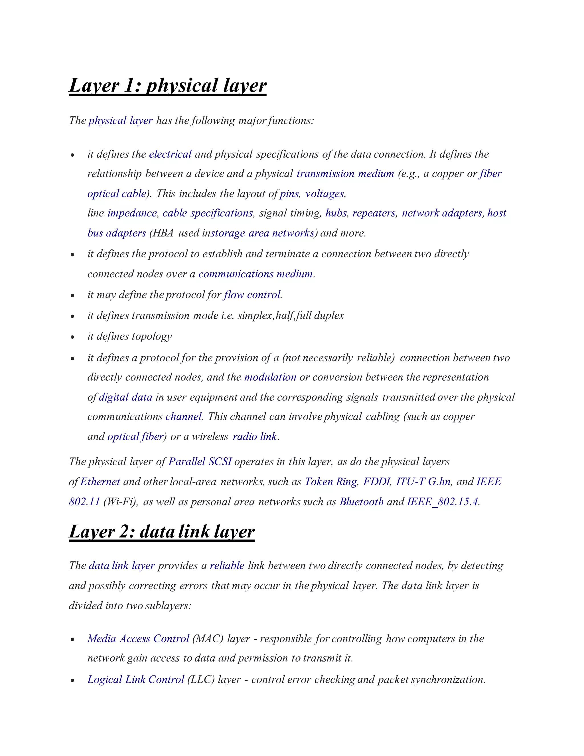
![The transport layer controls the reliability of a given link through flow
control, segmentation/desegmentation, and error control. Some protocols are state- and
connection-oriented. This means that the transport layer can keep track of the segments and
retransmit those that fail. The transport layer also provides the acknowledgement of the
successful data transmission and sends the next data if no errors occurred. The transport layer
creates packets out of the message received from the application layer. Packetizing is a process
of dividing the long message into smaller messages.
OSI defines five classes of connection-mode transport protocols ranging from class 0 (which is
also known as TP0 and provides the fewest features) to class 4 (TP4, designed for less reliable
networks, similar to the Internet). Class 0 contains no error recovery, and was designed for use
on network layers that provide error-free connections. Class 4 is closest to TCP, although TCP
contains functions, such as the graceful close, which OSI assigns to the session layer. Also, all
OSI TP connection-mode protocol classes provide expedited data and preservation of record
boundaries. Detailed characteristics of TP0-4 classes are shown in the following table:[4]
An easy way to visualize the transport layer is to compare it with a post office, which deals with
the dispatch and classification of mail and parcels sent. Do remember, however, that a post
office manages the outer envelope of mail. Higher layers may have the equivalent of double
envelopes, such as cryptographic presentation services that can be read by the addressee only.
Roughly speaking, tunneling protocols operate at the transport layer, such as carrying non-IP
protocols such as IBM's SNA or Novell's IPX over an IP network, or end-to-end encryption
with IPsec. While Generic Routing Encapsulation (GRE) might seem to be a network-layer
protocol, if the encapsulation of the payload takes place only at endpoint, GRE becomes closer
to a transport protocol that uses IP headers but contains complete frames or packets to deliver to
an endpoint. L2TP carries PPP frames inside transport packet.
Although not developed under the OSI Reference Model and not strictly conforming to the OSI
definition of the transport layer, the Transmission Control Protocol (TCP) and the User
Datagram Protocol (UDP) of the Internet Protocol Suite are commonly categorized as layer-4
protocols within OSI.
Layer 5: session layer](https://image.slidesharecdn.com/osimodel-141022105733-conversion-gate02/75/OsiI-model-3-2048.jpg)
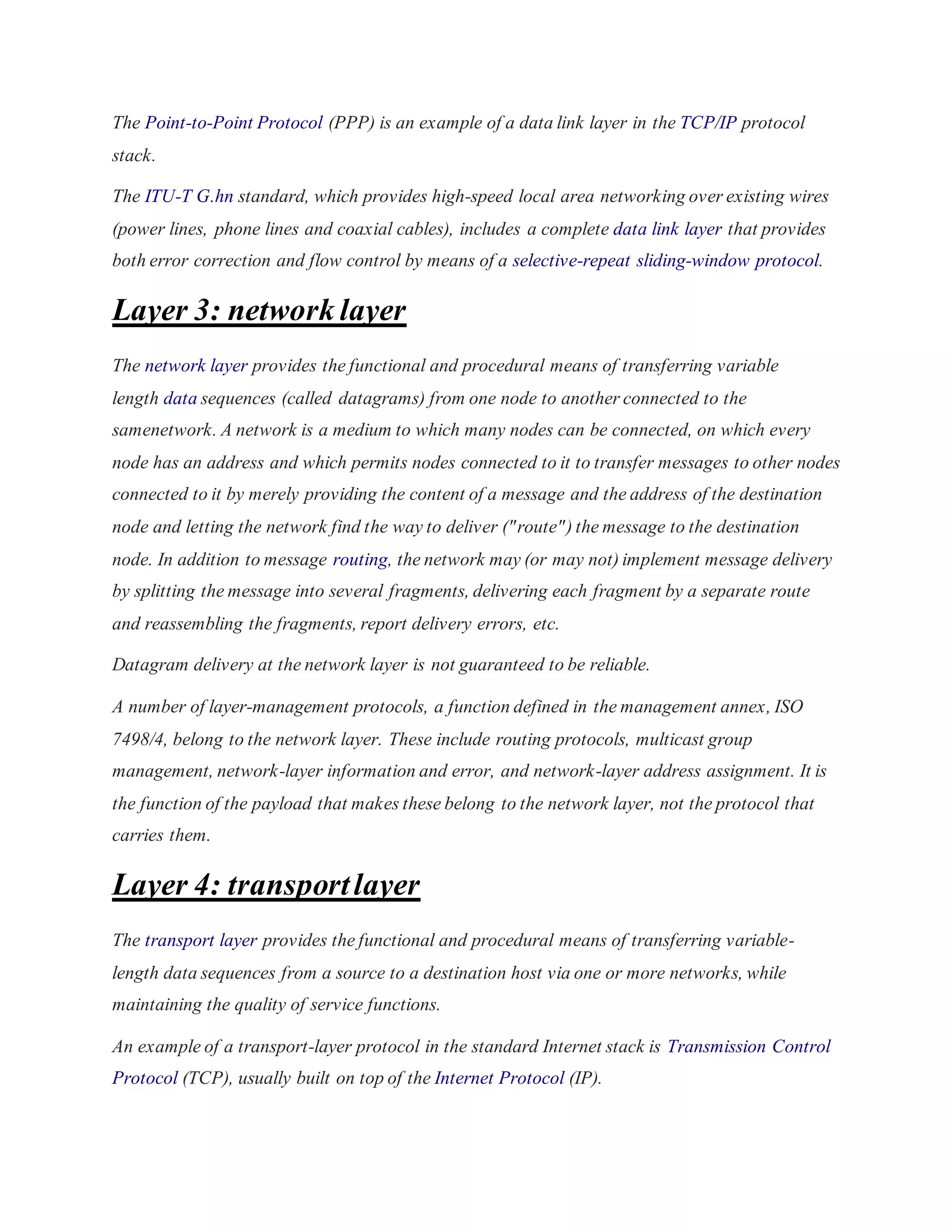
![The session layer controls the dialogues (connections) between computers. It establishes,
manages and terminates the connections between the local and remote application. It provides
for full-duplex, half-duplex, or simplex operation, and establishes checkpointing, adjournment,
termination, and restart procedures. The OSI model made this layer responsible for graceful
close of sessions, which is a property of the Transmission Control Protocol, and also for session
checkpointing and recovery, which is not usually used in the Internet Protocol Suite. The session
layer is commonly implemented explicitly in application environments that use remote procedure
calls.
Layer 6: presentation layer
The presentation layer establishes context between application-layer entities, in which the
application-layer entities may use different syntax and semantics if the presentation service
provides a big mapping between them. If a mapping is available, presentation service data unit s
are encapsulated into session protocol data units, and passed down the protocol stack.
This layer provides independence from data representation (e.g., encryption) by translating
between application and network formats. The presentation layer transforms data into the form
that the application accepts. This layer formats and encrypts data to be sent across a network. It
is sometimes called the syntax layer.[5]
The original presentation structure used the Basic Encoding Rules of Abstract Syntax Notation
One (ASN.1), with capabilities such as converting an EBCDIC-coded text file to anASCII-coded
file, or serialization of objects and other data structures from and to XML.
Layer 7: application layer
The application layer is the OSI layer closest to the end user, which means both the OSI
application layer and the user interact directly with the software application. This layer interacts
with software applications that implement a communicating component. Such application
programs fall outside the scope of the OSI model. Application-layer functions typically include
identifying communication partners, determining resource availability, and synchronizing
communication. When identifying communication partners, the application layer determines the
identity and availability of communication partners for an application with data to transmit.](https://image.slidesharecdn.com/osimodel-141022105733-conversion-gate02/75/OsiI-model-4-2048.jpg)
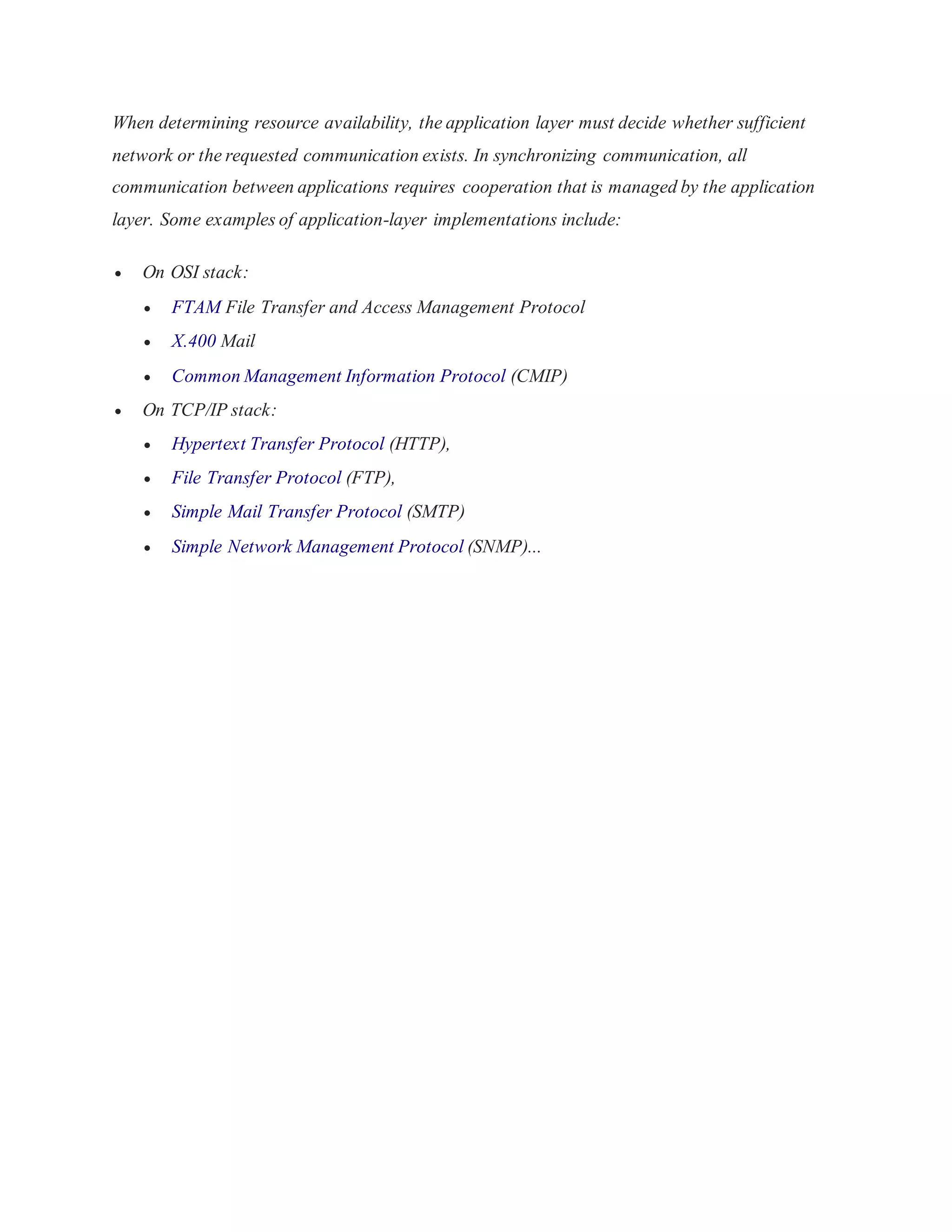

The document describes the seven layers of the OSI model: 1. The physical layer defines electrical specifications for data connections and transmission modes. 2. The data link layer provides error detection and flow control between directly connected nodes. 3. The network layer transfers data across networks by routing messages and delivering datagrams. 4. The transport layer transfers variable-length data sequences across networks while maintaining quality of service.


![ELEKTRIK - ASAS 1[PERKAKASAN DAN MENGENAL]](https://cdn.slidesharecdn.com/ss_thumbnails/alatpengujian-150403073049-conversion-gate01-thumbnail.jpg?width=640&height=640&fit=bounds)


